- Table of Contents
-
- 03-IP Routing Volume
- 00-IP Routing Volume Organization
- 01-IP Routing Overview
- 02-Static Routing Configuration
- 03-RIP Configuration
- 04-OSPF Configuration
- 05-IS-IS Configuration
- 06-BGP Configuration
- 07-IPv6 Static Routing Configuration
- 08-IPv6 Ripng Configuration
- 09-IPv6 OSPFv3 Configuration
- 10-IPv6 IS-IS Configuration
- 11-IPv6 BGP Configuration
- 12-Routing Policy Configuration
- Related Documents
-
| Title | Size | Download |
|---|---|---|
| 03-RIP Configuration | 277.62 KB |
Table of Contents
Configuring RIP Basic Functions
Configuring an Additional Routing Metric
Configuring RIPv2 Route Summarization
Disabling Host Route Reception
Configuring Inbound/Outbound Route Filtering
Configuring a Priority for RIP
Configuring RIP Route Redistribution
Configuring RIP Network Optimization
Configuring Split Horizon and Poison Reverse
Configuring the Maximum Number of Load Balanced Routes
Enabling Zero Field Check on Incoming RIPv1 Messages
Enabling Source IP Address Check on Incoming RIP Updates
Configuring RIPv2 Message Authentication
Configuring RIP-to-MIB Binding
Configuring the RIP Packet Sending Rate
Displaying and Maintaining RIP
Configuring RIP Route Redistribution
Configuring an Additional Metric for a RIP Interface
Configuring RIP to Advertise a Summary Route
1 RIP Configuration
![]()
The term “router” in this document refers to a router in a generic sense or a Layer 3 switch.
When configuring RIP, go to these sections for information you are interested in:
l Configuring RIP Basic Functions
l Configuring RIP Route Control
l Configuring RIP Network Optimization
l Displaying and Maintaining RIP
RIP Overview
RIP is a simple Interior Gateway Protocol (IGP), mainly used in small-sized networks, such as academic networks and simple LANs. RIP is not applicable to complex networks.
RIP is still widely used in practical networking due to easier implementation, configuration and maintenance than OSPF and IS-IS.
Operation of RIP
Introduction
RIP is a distance vector routing protocol, using UDP packets for exchanging information through port 520.
RIP uses a hop count to measure the distance to a destination. The hop count from a router to a directly connected network is 0. The hop count from a router to a directly connected router is 1. To limit convergence time, the range of RIP metric value is from 0 to 15. A metric value of 16 (or greater) is considered infinite, which means the destination network is unreachable. That is why RIP is not suitable for large-scaled networks.
RIP prevents routing loops by implementing the split horizon and poison reverse functions.
RIP routing table
A RIP router has a routing table containing routing entries of all reachable destinations, and each routing entry contains:
l Destination address: IP address of a host or a network.
l Next hop: IP address of the adjacent router’s interface to reach the destination.
l Egress interface: Packet outgoing interface.
l Metric: Cost from the local router to the destination.
l Route time: Time elapsed since the routing entry was last updated. The time is reset to 0 every time the routing entry is updated.
l Route tag: Identifies a route, used in a routing policy to flexibly control routes. For information about routing policy, refer to Routing Policy Configuration in the IP Routing Volume.
RIP timers
RIP employs four timers, update, timeout, suppress, and garbage-collect.
l The update timer defines the interval between routing updates.
l The timeout timer defines the route aging time. If no update for a route is received within the aging time, the metric of the route is set to 16 in the routing table.
l The suppress timer defines how long a RIP route stays in the suppressed state. When the metric of a route is 16, the route enters the suppressed state. In the suppressed state, only routes which come from the same neighbor and whose metric is less than 16 will be received by the router to replace unreachable routes.
l The garbage-collect timer defines the interval from when the metric of a route becomes 16 to when it is deleted from the routing table. During the garbage-collect timer length, RIP advertises the route with the routing metric set to 16. If no update is announced for that route after the garbage-collect timer expires, the route will be deleted from the routing table.
Routing loops prevention
RIP is a distance vector (D-V) routing protocol. Since a RIP router advertises its own routing table to neighbors, routing loops may occur.
RIP uses the following mechanisms to prevent routing loops.
l Counting to infinity. The metric value of 16 is defined as unreachable. When a routing loop occurs, the metric value of the route will increment to 16.
l Split horizon. A router does not send the routing information learned from a neighbor to the neighbor to prevent routing loops and save bandwidth.
l Poison reverse. A router sets the metric of routes received from a neighbor to 16 and sends back these routes to the neighbor to help delete such information from the neighbor’s routing table.
l Triggered updates. A router advertises updates once the metric of a route is changed rather than after the update period expires to speed up network convergence.
Operation of RIP
The following procedure describes how RIP works.
1) After RIP is enabled, the router sends request messages to neighboring routers. Neighboring routers return Response messages including information about their routing tables.
2) After receiving such information, the router updates its local routing table, and sends triggered update messages to its neighbors. All routers on the network do the same to keep the latest routing information.
3) By default, a RIP router sends its routing table to neighbors every 30 seconds.
4) RIP ages out routes by adopting an aging mechanism to keep only valid routes.
RIP Version
RIP has two versions, RIPv1 and RIPv2.
RIPv1, a classful routing protocol, supports message advertisement via broadcast only. RIPv1 protocol messages do not carry mask information, which means it can only recognize routing information of natural networks such as Class A, B, C. That is why RIPv1 does not support discontiguous subnets.
RIPv2 is a classless routing protocol. Compared with RIPv1, RIPv2 has the following advantages.
l Supporting route tags. Route tags are used in routing policies to flexibly control routes.
l Supporting masks, route summarization and Classless Inter-Domain Routing (CIDR).
l Supporting designated next hops to select the best next hops on broadcast networks.
l Supporting multicast routing update to reduce resource consumption.
l Supporting plain text authentication and MD5 authentication to enhance security.
![]()
RIPv2 has two types of message transmission: broadcast and multicast. Multicast is the default type using 224.0.0.9 as the multicast address. The interface working in the RIPv2 broadcast mode can also receive RIPv1 messages.
RIP Message Format
RIPv1 message format
A RIPv1 message consists of a header and up to 25 route entries.
Figure 1-1 shows the format of RIPv1 message.
Figure 1-1 RIPv1 Message Format
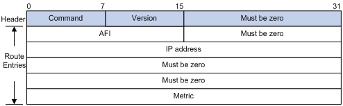
l Command: Type of message. 1 indicates request, and 2 indicates response.
l Version: Version of RIP, 0x01 for RIPv1.
l AFI: Address Family Identifier, 2 for IP.
l IP Address: Destination IP address of the route. It can be a natural network, subnet or a host address.
l Metric: Cost of the route.
RIPv2 message format
The format of RIPv2 message is similar to RIPv1. Figure 1-2 shows it.
Figure 1-2 RIPv2 Message Format
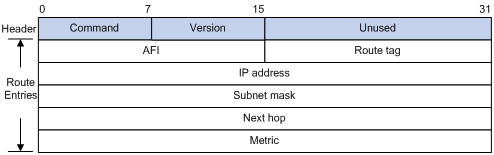
The differences from RIPv1 are stated as following.
l Version: Version of RIP. For RIPv2 the value is 0x02.
l Route Tag: Route Tag.
l IP Address: Destination IP address. It can be a natural network address, subnet address or host address.
l Subnet Mask: Mask of the destination address.
l Next Hop: If set to 0.0.0.0, it indicates that the originator of the route is the best next hop; otherwise it indicates a next hop better than the originator of the route.
RIPv2 authentication message format
RIPv2 sets the AFI field of the first route entry to 0xFFFF to identify authentication information. See Figure 1-3.
Figure 1-3 RIPv2 Authentication Message
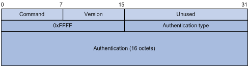
l Authentication Type: A value of 2 represents plain text authentication, while a value of 3 represents MD5.
l Authentication: Authentication data, including password information when plain text authentication is adopted or including key ID, MD5 authentication data length and sequence number when MD5 authentication is adopted.
![]()
l RFC 1723 only defines plain text authentication. For information about MD5 authentication, refer to RFC 2453 “RIP Version 2”.
l With RIPv1, you can configure the authentication mode in interface view. However, the configuration will not take effect because RIPv1 does not support authentication.
Supported RIP Features
The current implementation supports the following RIP features.
l RIPv1 and RIPv2
l RIP multi-instance. RIP can serve as the IGP running between CE and PE on a BGP/MPLS VPN network. For related information, refer to MPLS L3VPN Configuration in the MPLS Volume.
Protocols and Standards
l RFC 1058: Routing Information Protocol
l RFC 1723: RIP Version 2 - Carrying Additional Information
l RFC 1721: RIP Version 2 Protocol Analysis
l RFC 1722: RIP Version 2 Protocol Applicability Statement
l RFC 1724: RIP Version 2 MIB Extension
l RFC 2082: RIPv2 MD5 Authentication
l RFC 2091: Triggered Extensions to RIP to Support Demand Circuits
Configuring RIP Basic Functions
Configuration Prerequisites
Before configuring RIP basic functions, configure IP addresses for interfaces, making all adjacent nodes reachable to each other at the network layer.
Configuration Procedure
Enabling RIP and a RIP interface
Follow these steps to enable RIP:
|
Use the command… |
Remarks |
|
|
Enter system view |
system-view |
–– |
|
Enable a RIP process and enter RIP view |
rip [ process-id ] [ vpn-instance vpn-instance-name ] |
Required Not enabled by default |
|
Enable RIP on the interface attached to the specified network |
network network-address |
Required Disabled by default |
![]()
l If you make some RIP configurations in interface view before enabling RIP, those configurations will take effect after RIP is enabled.
l RIP runs only on the interfaces residing on the specified networks. Therefore, you need to specify the network after enabling RIP to validate RIP on a specific interface.
l You can enable RIP on all interfaces using the command network 0.0.0.0.
l If a physical interface is attached to multiple networks, you cannot advertise these networks in different RIP processes.
Configuring the interface behavior
Follow these steps to configure the interface behavior:
|
To do… |
Use the command… |
Remarks |
|
Enter system view |
system-view |
–– |
|
Enter RIP view |
rip [ process-id ] [ vpn-instance vpn-instance-name ] |
–– |
|
Disable an or all interfaces from sending routing updates (the interfaces can still receive updates) |
silent-interface { all | interface-type interface-number } |
Optional All interfaces can send routing updates by default. |
|
Return to system view |
quit |
— |
|
Enter interface view |
interface interface-type interface-number |
— |
|
Enable the interface to receive RIP messages |
rip input |
Optional Enabled by default |
|
Enable the interface to send RIP messages |
rip output |
Optional Enabled by default |
Configuring a RIP version
You can configure a RIP version in RIP or interface view.
l If neither global nor interface RIP version is configured, the interface sends RIPv1 broadcasts and can receive RIPv1 broadcast and unicast packets, and RIPv2 broadcast, multicast, and unicast packets.
l If an interface has no RIP version configured, it uses the global RIP version; otherwise it uses the RIP version configured on it.
l With RIPv1 configured, an interface sends RIPv1 broadcasts, and can receive RIPv1 broadcasts and RIPv1 unicasts.
l With RIPv2 configured, a multicast interface sends RIPv2 multicasts and can receive RIPv2 unicasts, broadcasts and multicasts.
l With RIPv2 configured, a broadcast interface sends RIPv2 broadcasts and can receive RIPv1 unicasts, and broadcasts, and RIPv2 broadcasts, multicasts and unicasts.
Follow these steps to configure a RIP version:
|
To do… |
Use the command… |
Remarks |
|
Enter system view |
system-view |
–– |
|
Enter RIP view |
rip [ process-id ] [ vpn-instance vpn-instance-name ] |
–– |
|
Specify a global RIP version |
version { 1 | 2 } |
Optional By default, if an interface has a RIP version specified, the version takes precedence over the global one. If no RIP version is specified for an interface, the interface can send RIPv1 broadcasts, and receive RIPv1 broadcasts, unicasts, RIPv2 broadcasts, multicasts and unicasts. |
|
Return to system view |
quit |
— |
|
Enter interface view |
interface interface-type interface-number |
–– |
|
Specify a RIP version for the interface |
rip version { 1 | 2 [ broadcast | multicast ] } |
Optional |
Configuring RIP Route Control
In complex networks, you need to configure advanced RIP features.
This section covers the following topics:
l Configuring an Additional Routing Metric
l Configuring RIPv2 Route Summarization
l Disabling Host Route Reception
l Configuring Inbound/Outbound Route Filtering
l Configuring a Priority for RIP
l Configuring RIP Route Redistribution
Before configuring RIP routing feature, complete the following tasks:
l Configure an IP address for each interface, and make sure all neighboring routers are reachable to each other.
l Configure RIP basic functions
Configuring an Additional Routing Metric
An additional routing metric (hop count) can be added to the metric of an inbound or outbound RIP route.
The outbound additional metric is added to the metric of a sent route, and the route’s metric in the routing table is not changed.
The inbound additional metric is added to the metric of a received route before the route is added into the routing table, and the route’s metric is changed. If the sum of the additional metric and the original metric is greater than 16, the metric of the route will be 16.
Follow these steps to configure additional routing metrics:
|
To do… |
Use the command… |
Remarks |
|
Enter system view |
system-view |
–– |
|
Enter interface view |
interface interface-type interface-number |
–– |
|
Define an inbound additional routing metric |
rip metricin [ route-policy route-policy-name ] value |
Optional 0 by default |
|
Define an outbound additional routing metric |
rip metricout [ route-policy route-policy-name ] value |
Optional 1 by default |
Configuring RIPv2 Route Summarization
Route summarization means that subnets in a natural network are summarized into a natural network that is sent to other networks. This feature can reduce the size of routing tables.
After route summarization, the smallest metric among all the summarized routes is used as the metric of the summary route.
Enabling RIPv2 route automatic summarization
You can disable RIPv2 route automatic summarization if you want to advertise all subnet routes.
Follow these steps to enable RIPv2 route automatic summarization:
|
Use the command… |
Remarks |
|
|
Enter system view |
system-view |
–– |
|
Enter RIP view |
rip [ process-id ] [ vpn-instance vpn-instance-name ] |
–– |
|
Enable RIPv2 automatic route summarization |
summary |
Optional Enabled by default |
Advertising a summary route
You can configure RIPv2 to advertise a summary route on the specified interface.
To do so, use the following commands:
|
To do… |
Use the command… |
Remarks |
|
Enter system view |
system-view |
–– |
|
Enter RIP view |
rip [ process-id ] [ vpn-instance vpn-instance-name ] |
–– |
|
Disable RIPv2 automatic route summarization |
undo summary |
Required Enabled by default |
|
Return to system view |
quit |
— |
|
Enter interface view |
interface interface-type interface-number |
— |
|
Advertise a summary route |
rip summary-address ip-address { mask | mask-length } |
Required |
![]()
You need to disable RIPv2 route automatic summarization before advertising a summary route on an interface.
Disabling Host Route Reception
Sometimes a router may receive from the same network many host routes, which are not helpful for routing and consume a large amount of network resources. In this case, you can disable RIP from receiving host routes to save network resources.
Follow these steps to disable RIP from receiving host routes:
|
To do… |
Use the command… |
Remarks |
|
Enter system view |
system-view |
— |
|
Enter RIP view |
rip [ process-id ] [ vpn-instance vpn-instance-name ] |
— |
|
Disable RIP from receiving host routes |
undo host-route |
Required Enabled by default |
![]()
RIPv2 can be disabled from receiving host routes, but RIPv1 cannot.
Advertising a Default Route
You can configure RIP to advertise a default route with a specified metric to RIP neighbors.
l In RIP view, you can configure all the interfaces of the RIP process to advertise a default route; in interface view, you can configure a RIP interface of the RIP process to advertise a default route. The latter takes precedence over the former on the interface.
l If a RIP process is enabled to advertise a default route, to disable an interface of the RIP process from default route advertisement, you can use the rip default-route no-originate command on the interface.
Follow these steps to configure RIP to advertise a default route:
|
To do… |
Use the command… |
Remarks |
|
Enter system view |
system-view |
–– |
|
Enter RIP view |
rip [ process-id ] [ vpn-instance vpn-instance-name ] |
–– |
|
Enable RIP to advertise a default route |
default-route { only | originate } [ cost cost ] |
Optional Not enabled by default |
|
Return to system view |
quit |
–– |
|
Enter interface view |
interface interface-type interface-number |
–– |
|
Configure the RIP interface to advertise a default route |
rip default-route { { only | originate } [ cost cost ] | no-originate } |
Optional By default, a RIP interface can advertise a default route if the RIP process is configured with default route advertisement. |
![]()
The router enabled to advertise a default route does not receive default routes from RIP neighbors.
Configuring Inbound/Outbound Route Filtering
The device supports route filtering. You can filter routes by configuring the inbound and outbound route filtering policies by referencing an ACL or IP prefix list. You can also configure the router to receive only routes from a specified neighbor.
Follow these steps to configure route filtering:
|
To do… |
Use the command… |
Remarks |
|
Enter system view |
system-view |
–– |
|
Enter RIP view |
rip [ process-id ] [ vpn-instance vpn-instance-name ] |
–– |
|
Configure the filtering of incoming routes |
filter-policy { acl-number | gateway ip-prefix-name | ip-prefix ip-prefix-name [ gateway ip-prefix-name ] } import [ interface-type interface-number ] |
Required Not configured by default |
|
Configure the filtering of outgoing routes |
filter-policy { acl-number | ip-prefix ip-prefix-name } export [ protocol [ process-id ] | interface-type interface-number ] |
Required Not configured by default |
![]()
l Using the filter-policy import command filters incoming routes. Routes not passing the filtering will be neither installed into the routing table nor advertised to neighbors.
l Using the filter-policy export command filters outgoing routes, including routes redistributed with the import-route command.
Configuring a Priority for RIP
Multiple IGP protocols may run in a router. If you want RIP routes to have a higher priority than those learned by other routing protocols, you can assign RIP a smaller priority value to influence optimal route selection.
Follow these steps to configure a priority for RIP:
|
To do… |
Use the command… |
Remarks |
|
Enter system view |
system-view |
–– |
|
Enter RIP view |
rip [ process-id ] [ vpn-instance vpn-instance-name ] |
–– |
|
Configure a priority for RIP |
preference [ route-policy route-policy-name ] value |
Optional 100 by default |
Configuring RIP Route Redistribution
If a router runs RIP and other routing protocols, you can configure RIP to redistribute OSPF, IS-IS, BGP, static, or direct routes.
Follow these steps to configure RIP route redistribution:
|
To do… |
Use the command… |
Remarks |
|
Enter system view |
system-view |
–– |
|
Enter RIP view |
rip [ process-id ] [ vpn-instance vpn-instance-name ] |
–– |
|
Configure a default metric for redistributed routes |
default cost value |
Optional The default metric of a redistributed route is 0 by default. |
|
Redistribute routes from another protocol |
import-route protocol [ process-id | all-processes | allow-ibgp ] [ cost cost | route-policy route-policy-name | tag tag ] * |
Required No redistribution is configured by default. |
![]()
Only active routes can be redistributed. You can use the display ip routing-table protocol command to display route state information.
Configuring RIP Network Optimization
Complete the following tasks before configuring RIP network optimization:
l Configure network addresses for interfaces, and make neighboring nodes reachable to each other;
l Configure RIP basic functions.
Configuring RIP Timers
Follow these steps to configure RIP timers:
|
To do… |
Use the command… |
Remarks |
|
Enter system view |
system-view |
–– |
|
Enter RIP view |
rip [ process-id ] [ vpn-instance vpn-instance-name ] |
–– |
|
Configure values for RIP timers |
timers { garbage-collect garbage-collect-value | suppress suppress-value | timeout timeout-value | update update-value } * |
Optional The default update timer, timeout timer, suppress timer, and garbage-collect timer are 30s, 180s, 120s and 120s respectively. |
![]()
Based on network performance, you need to make RIP timers of RIP routers identical to each other to avoid unnecessary traffic or route oscillation.
Configuring Split Horizon and Poison Reverse
![]()
If both split horizon and poison reverse are configured, only the poison reverse function takes effect.
Enabling split horizon
The split horizon function disables an interface from sending routes received from the interface to prevent routing loops between adjacent routers.
Follow these steps to enable split horizon:
|
To do… |
Use the command… |
Remarks |
|
Enter system view |
system-view |
— |
|
Enter interface view |
interface interface-type interface-number |
— |
|
Enable split horizon |
rip split-horizon |
Optional Enabled by default |
Enabling poison reverse
The poison reverse function allows an interface to advertise the routes received from it, but the metric of these routes is set to 16, making them unreachable.
Follow these steps to enable poison reverse:
|
To do… |
Use the command… |
Remarks |
|
Enter system view |
system-view |
— |
|
Enter interface view |
interface interface-type interface-number |
— |
|
Enable poison reverse |
rip poison-reverse |
Required Disabled by default |
Configuring the Maximum Number of Load Balanced Routes
Follow these steps to configure the maximum number of load balanced routes:
|
To do… |
Use the command… |
Remarks |
|
Enter system view |
system-view |
–– |
|
Enter RIP view |
rip [ process-id ] [ vpn-instance vpn-instance-name ] |
–– |
|
Configure the maximum number of load balanced routes |
maximum load-balancing number |
Optional The default maximum number is 4. |
Enabling Zero Field Check on Incoming RIPv1 Messages
Some fields in the RIPv1 message must be zero. These fields are called zero fields. You can enable zero field check on received RIPv1 messages. If such a field contains a non-zero value, the RIPv1 message will not be processed. If you are sure that all messages are trusty, you can disable zero field check to save CPU resources.
Follow these steps to enable zero field check on incoming RIPv1 messages:
|
To do… |
Use the command… |
Remarks |
|
Enter system view |
system-view |
–– |
|
Enter RIP view |
rip [ process-id ] [ vpn-instance vpn-instance-name ] |
–– |
|
Enable zero field check on received RIPv1 messages |
checkzero |
Optional Enabled by default |
Enabling Source IP Address Check on Incoming RIP Updates
RIP compares the source IP address of the message with the IP address of the interface. If they are not in the same network segment, RIP discards the message.
Follow these steps to enable source IP address check on incoming RIP updates:
|
To do… |
Use the command… |
Remarks |
|
Enter system view |
system-view |
–– |
|
Enter RIP view |
rip [ process-id ] [ vpn-instance vpn-instance-name ] |
–– |
|
Enable source IP address check on incoming RIP messages |
validate-source-address |
Optional Enabled by default |
![]()
The source IP address check feature should be disabled if the RIP neighbor is not directly connected.
Configuring RIPv2 Message Authentication
RIPv2 supports two authentication modes: plain text and MD5.
In plain text authentication, the authentication information is sent with the RIP message, which however cannot meet high security needs.
Follow these steps to configure RIPv2 message authentication:
|
To do… |
Use the command… |
Remarks |
|
Enter system view |
system-view |
–– |
|
Enter interface view |
interface interface-type interface-number |
–– |
|
Configure RIPv2 authentication |
rip authentication-mode { md5 { rfc2082 key-string key-id | rfc2453 key-string } | simple password } |
Required |
Specifying a RIP Neighbor
Usually, RIP sends messages to broadcast or multicast addresses. On non broadcast or multicast links, you need to manually specify RIP neighbors. If a specified neighbor is not directly connected, you must disable source address check on incoming updates.
Follow these steps to specify a RIP neighbor:
|
To do… |
Use the command… |
Remarks |
|
Enter system view |
system-view |
–– |
|
Enter RIP view |
rip [ process-id ] [ vpn-instance vpn-instance-name ] |
–– |
|
Specify a RIP neighbor |
peer ip-address |
Required |
|
Disable source address check on incoming RIP updates |
undo validate-source-address |
Required Not disabled by default |
![]()
You need not use the peer ip-address command when the neighbor is directly connected; otherwise the neighbor may receive both the unicast and multicast (or broadcast) of the same routing information.
Configuring RIP-to-MIB Binding
This task allows you to enable a specific RIP process to receive SNMP requests.
Follow these steps to bind RIP to MIB:
|
To do… |
Use the command… |
Remarks |
|
Enter system view |
system-view |
–– |
|
Bind RIP to MIB |
rip mib-binding process-id |
Optional By default, MIB is bound to RIP process 1. |
Configuring the RIP Packet Sending Rate
RIP periodically sends routing information in RIP packets to RIP neighbors.
Sending large numbers of RIP packets at the same time may affect device performance and consume large network bandwidth. To solve this problem, you can specify the maximum number of RIP packets that can be sent at the specified interval.
Follow these steps to configure the RIP packet sending rate:
|
To do… |
Use the command… |
Remarks |
|
Enter system view |
system-view |
–– |
|
Enable a RIP process and enter RIP view |
rip [ process-id ] [ vpn-instance vpn-instance-name ] |
–– |
|
Configure the maximum number of RIP packets that can be sent at the specified interval |
output-delay time count count |
Optional By default, an interface sends up to three RIP packets every 20 milliseconds. |
Displaying and Maintaining RIP
|
Use the command… |
Remarks |
|
|
Display RIP current status and configuration information |
display rip [ process-id | vpn-instance vpn-instance-name ] |
Available in any view |
|
Display all active routes in RIP database |
display rip process-id database |
|
|
Display RIP interface information |
display rip process-id interface [ interface-type interface-number ] |
|
|
Display routing information about a specified RIP process |
display rip process-id route [ statistics | ip-address { mask | mask-length } | peer ip-address ] |
|
|
Clear the statistics of a RIP process |
reset rip process-id statistics |
Available in user view |
RIP Configuration Examples
Configuring RIP Version
Network requirements
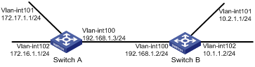
As shown in Figure 1-4, enable RIPv2 on all interfaces on Switch A and Switch B.
Network diagram
Figure 1-4 Network diagram for RIP version configuration
Configuration procedure
1) Configure an IP address for each interface (only the IP address configuration for the VLAN interfaces is given in the following examples)
# Configure Switch A.
<SwitchA> system-view
[SwitchA] interface vlan-interface 100
[SwitchA-Vlan-interface100] ip address 192.168.1.3 24
# Configure Switch B.
<SwitchB> system-view
[SwitchB] interface vlan-interface 100
[SwitchB-Vlan-interface100] ip address 192.168.1.2 24
2) Configure basic RIP functions
# Configure Switch A.
[SwitchA] rip
[SwitchA-rip-1] network 192.168.1.0
[SwitchA-rip-1] network 172.16.0.0
[SwitchA-rip-1] network 172.17.0.0
# Configure Switch B.
[SwitchB] rip
[SwitchB-rip-1] network 192.168.1.0
[SwitchB-rip-1] network 10.0.0.0
# Display the RIP routing table of Switch A.
[SwitchA] display rip 1 route
Route Flags: R - RIP, T - TRIP
P - Permanent, A - Aging, S - Suppressed, G - Garbage-collect
--------------------------------------------------------------------------
Peer 192.168.1.2 on Vlan-interface100
Destination/Mask Nexthop Cost Tag Flags Sec
10.0.0.0/8 192.168.1.2 1 0 RA 11
From the routing table, you can find that RIPv1 uses a natural mask.
3) Configure RIP version
# Configure RIPv2 on Switch A.
[SwitchA] rip
[SwitchA-rip-1] version 2
[SwitchA-rip-1] undo summary
# Configure RIPv2 on Switch B.
[SwitchB] rip
[SwitchB-rip-1] version 2
[SwitchB-rip-1] undo summary
# Display the RIP routing table on Switch A.
[SwitchA] display rip 1 route
Route Flags: R - RIP, T - TRIP
P - Permanent, A - Aging, S - Suppressed, G - Garbage-collect
--------------------------------------------------------------------------
Peer 192.168.1.2 on Vlan-interface100
Destination/Mask Nexthop Cost Tag Flags Sec
10.0.0.0/8 192.168.1.2 1 0 RA 50
10.2.1.0/24 192.168.1.2 1 0 RA 16
10.1.1.0/24 192.168.1.2 1 0 RA 16
From the routing table, you can see RIPv2 uses classless subnet mask.
![]()
Since RIPv1 routing information has a long aging time, it will still exist until it ages out after RIPv2 is configured.
Configuring RIP Route Redistribution
Network requirements
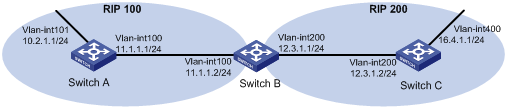
l Two RIP processes are running on Switch B, which communicates with Switch A through RIP 100 and with Switch C through RIP 200.
l Configure route redistribution on Switch B to make RIP 200 redistribute direct routes and routes from RIP 100. Thus, Switch C can learn routes destined for 10.2.1.0/24 and 11.1.1.0/24, while Switch A cannot learn routes destined for 12.3.1.0/24 and 16.4.1.0/24.
l Configure a filtering policy on Switch B to filter out the route 10.2.1.1/24 from RIP 100, making the route not advertised to Switch C.
Network diagram
Figure 1-5 Network diagram for RIP route redistribution configuration
Configuration procedure
1) Configure an IP address for each interface (Omitted).
2) Configure basic RIP functions.
# Enable RIP 100 and specify RIP version 2 on Switch A.
<SwitchA> system-view
[SwitchA] rip 100
[SwitchA-rip-100] network 10.0.0.0
[SwitchA-rip-100] network 11.0.0.0
[SwitchA-rip-100] version 2
[SwitchA-rip-100] undo summary
[SwitchA-rip-100] quit
# Enable RIP 100 and RIP 200 and specify RIP version 2 on Switch B.
<SwitchB> system-view
[SwitchB] rip 100
[SwitchB-rip-100] network 11.0.0.0
[SwitchB-rip-100] version 2
[SwitchB-rip-100] undo summary
[SwitchB-rip-100] quit
[SwitchB] rip 200
[SwitchB-rip-200] network 12.0.0.0
[SwitchB-rip-200] version 2
[SwitchB-rip-200] undo summary
[SwitchB-rip-200] quit
# Enable RIP 200 and specify RIP version 2 on Switch C.
<SwitchC> system-view
[SwitchC] rip 200
[SwitchC-rip-200] network 12.0.0.0
[SwitchC-rip-200] network 16.0.0.0
[SwitchC-rip-200] version 2
[SwitchC-rip-200] undo summary
# Display the routing table of Switch C.
[SwitchC] display ip routing-table
Routing Tables: Public
Destinations : 6 Routes : 6
Destination/Mask Proto Pre Cost NextHop Interface
12.3.1.0/24 Direct 0 0 12.3.1.2 Vlan200
12.3.1.2/32 Direct 0 0 127.0.0.1 InLoop0
16.4.1.0/24 Direct 0 0 16.4.1.1 Vlan400
16.4.1.1/32 Direct 0 0 127.0.0.1 InLoop0
127.0.0.0/8 Direct 0 0 127.0.0.1 InLoop0
127.0.0.1/32 Direct 0 0 127.0.0.1 InLoop0
3) Configure route redistribution
# On Switch B, configure RIP 200 to redistribute direct routes and routes from RIP 100.
[SwitchB] rip 200
[SwitchB-rip-200] import-route rip 100
[SwitchB-rip-200] import-route direct
[SwitchB-rip-200] quit
# Display the routing table of Switch C.
[SwitchC] display ip routing-table
Routing Tables: Public
Destinations : 8 Routes : 8
Destination/Mask Proto Pre Cost NextHop Interface
10.2.1.0/24 RIP 100 1 12.3.1.1 Vlan200
11.1.1.0/24 RIP 100 1 12.3.1.1 Vlan200
12.3.1.0/24 Direct 0 0 12.3.1.2 Vlan200
12.3.1.2/32 Direct 0 0 127.0.0.1 InLoop0
16.4.1.0/24 Direct 0 0 16.4.1.1 Vlan400
16.4.1.1/32 Direct 0 0 127.0.0.1 InLoop0
127.0.0.0/8 Direct 0 0 127.0.0.1 InLoop0
127.0.0.1/32 Direct 0 0 127.0.0.1 InLoop0
4) Configure an filtering policy to filter redistributed routes
# Define ACL 2000 and reference it to a filtering policy to filter routes redistributed from RIP 100 on Switch B, making the route not advertised to Switch C.
[SwitchB] acl number 2000
[SwitchB-acl-basic-2000] rule deny source 10.2.1.1 0.0.0.255
[SwitchB-acl-basic-2000] rule permit
[SwitchB-acl-basic-2000] quit
[SwitchB] rip 200
[SwitchB-rip-200] filter-policy 2000 export rip 100
# Display the routing table of Switch C.
[SwitchC] display ip routing-table
Routing Tables: Public
Destinations : 7 Routes : 7
Destination/Mask Proto Pre Cost NextHop Interface
11.1.1.0/24 RIP 100 1 12.3.1.1 Vlan200
12.3.1.0/24 Direct 0 0 12.3.1.2 Vlan200
12.3.1.2/32 Direct 0 0 127.0.0.1 InLoop0
16.4.1.0/24 Direct 0 0 16.4.1.1 Vlan400
16.4.1.1/32 Direct 0 0 127.0.0.1 InLoop0
127.0.0.0/8 Direct 0 0 127.0.0.1 InLoop0
127.0.0.1/32 Direct 0 0 127.0.0.1 InLoop0
Configuring an Additional Metric for a RIP Interface
Network requirements
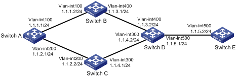
l RIP is enabled on all the interfaces of Switch A, Switch B, Switch C, Switch D, and Switch E. The switches are interconnected through RIPv2.
l Switch A has two links to Switch D. The link from Switch B to Switch D is more stable than that from Switch C to Switch D. Configure an additional metric for RIP routes received through VLAN-interface 200 on Switch A so that Switch A prefers the 1.1.5.0/24 network learned from Switch B.
Network diagram
Figure 1-6 Network diagram for RIP interface additional metric configuration
Configuration procedure
1) Configure IP addresses for the interfaces (omitted).
2) Configure RIP basic functions.
# Configure Switch A.
<SwitchA> system-view
[SwitchA] rip 1
[SwitchA-rip-1] network 1.0.0.0
[SwitchA-rip-1] version 2
[SwitchA-rip-1] undo summary
[SwitchA-rip-1] quit
# Configure Switch B.
<SwitchB> system-view
[SwitchB] rip 1
[SwitchB-rip-1] network 1.0.0.0
[SwitchB-rip-1] version 2
[SwitchB-rip-1] undo summary
# Configure Switch C.
<SwitchC> system-view
[SwitchB] rip 1
[SwitchC-rip-1] network 1.0.0.0
[SwitchC-rip-1] version 2
[SwitchC-rip-1] undo summary
# Configure Switch D.
<SwitchD> system-view
[SwitchD] rip 1
[SwitchD-rip-1] network 1.0.0.0
[SwitchD-rip-1] version 2
[SwitchD-rip-1] undo summary
# Configure Switch E.
<SwitchE> system-view
[SwitchE] rip 1
[SwitchE-rip-1] network 1.0.0.0
[SwitchE-rip-1] version 2
[SwitchE-rip-1] undo summary
# Display the IP routing table of Switch A.
[SwitchA] display rip 1 database
1.0.0.0/8, cost 0, ClassfulSumm
1.1.1.0/24, cost 0, nexthop 1.1.1.1, Rip-interface
1.1.2.0/24, cost 0, nexthop 1.1.2.1, Rip-interface
1.1.3.0/24, cost 1, nexthop 1.1.1.2
1.1.4.0/24, cost 1, nexthop 1.1.2.2
1.1.5.0/24, cost 2, nexthop 1.1.1.2
1.1.5.0/24, cost 2, nexthop 1.1.2.2
The display shows that there are two RIP routes to network 1.1.5.0/24. Their nexthops are Switch B (1.1.1.2) and Switch C (1.1.2.2) respectively, with the same cost of 2. Switch C is the nexthop router to reach network 1.1.4.0/24, with a cost of 1.
3) Configure an additional metric for the RIP interface.
# Configure an additional metric of 3 for VLAN-interface 200 on Switch A.
[SwitchA] interface vlan-interface 200
[SwitchA-Vlan-interface200] rip metricin 3
[SwitchA-Vlan-interface200] display rip 1 database
1.0.0.0/8, cost 0, ClassfulSumm
1.1.1.0/24, cost 0, nexthop 1.1.1.1, Rip-interface
1.1.2.0/24, cost 0, nexthop 1.1.2.1, Rip-interface
1.1.3.0/24, cost 1, nexthop 1.1.1.2
1.1.4.0/24, cost 2, nexthop 1.1.1.2
1.1.5.0/24, cost 2, nexthop 1.1.1.2
The display shows that there is only one RIP route to network 1.1.5.0/24, with the nexthop as Switch B (1.1.1.2) and a cost of 2.
Configuring RIP to Advertise a Summary Route
Network requirements
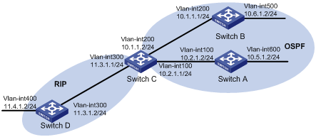
l Switch A and Switch B run OSPF, Switch D runs RIP, and Switch C runs OSPF and RIP.
l Configure RIP to redistribute OSPF routes on Switch C so that Switch D has routes destined for networks 10.1.1.0/24, 10.2.1.0/24, 10.5.1.0/24, and 10.6.1.0/24.
l Route summarization is configured on Switch C and only the summary route 10.0.0.0/8 is advertised, thus reducing the routing table size of Switch D.
Network diagram
Figure 1-7 Network diagram for RIP summary route advertisement
Configuration procedure
1) Configure IP addresses for interfaces (omitted)
2) Configure OSPF basic functions
# Configure Switch A.
<SwitchA> system-view
[SwitchA] ospf
[SwitchA-ospf-1] area 0
[SwitchA-ospf-1-area-0.0.0.0] network 10.5.1.0 0.0.0.255
[SwitchA-ospf-1-area-0.0.0.0] network 10.2.1.0 0.0.0.255
[SwitchA-ospf-1-area-0.0.0.0] quit
# Configure Switch B.
<SwitchB> system-view
[SwitchB] ospf
[SwitchB-ospf-1] area 0
[SwitchB-ospf-1-area-0.0.0.0] network 10.1.1.0 0.0.0.255
[SwitchB-ospf-1-area-0.0.0.0] network 10.6.1.0 0.0.0.255
[SwitchB-ospf-1-area-0.0.0.0] quit
# Configure Switch C.
<SwitchC> system-view
[SwitchC] ospf
[SwitchC-ospf-1] area 0
[SwitchC-ospf-1-area-0.0.0.0] network 10.1.1.0 0.0.0.255
[SwitchC-ospf-1-area-0.0.0.0] network 10.2.1.0 0.0.0.255
[SwitchC-ospf-1-area-0.0.0.0] quit
3) Configure RIP basic functions.
# Configure Switch C.
<SwitchC> system-view
[SwitchC] rip 1
[SwitchC-rip-1] network 11.3.1.0
[SwitchC-rip-1] version 2
[SwitchC-rip-1] undo summary
# Configure Switch D.
<SwitchD> system-view
[SwitchD] rip 1
[SwitchD-rip-1] network 11.0.0.0
[SwitchD-rip-1] version 2
[SwitchD-rip-1] undo summary
[SwitchD-rip-1] quit
# Configure RIP to redistribute the routes from OSPF process 1 and direct routes on Switch C.
[SwitchC-rip-1] import-route direct
[SwitchC-rip-1] import-route ospf 1
# Display the routing table information of Switch D.
[SwitchD] display ip routing-table
Routing Tables: Public
Destinations : 10 Routes : 10
Destination/Mask Proto Pre Cost NextHop Interface
10.1.1.0/24 RIP 100 1 11.3.1.1 Vlan300
10.2.1.0/24 RIP 100 1 11.3.1.1 Vlan300
10.5.1.0/24 RIP 100 1 11.3.1.1 Vlan300
10.6.1.0/24 RIP 100 1 11.3.1.1 Vlan300
11.3.1.0/24 Direct 0 0 11.3.1.2 Vlan300
11.3.1.2/32 Direct 0 0 127.0.0.1 InLoop0
11.4.1.0/24 Direct 0 0 11.4.1.2 Vlan400
11.4.1.2/32 Direct 0 0 127.0.0.1 InLoop0
127.0.0.0/8 Direct 0 0 127.0.0.1 InLoop0
127.0.0.1/32 Direct 0 0 127.0.0.1 InLoop0
4) Configure route summarization on Switch C and advertise only the summary route 10.0.0.0/8.
[SwitchC] interface vlan-interface 300
[SwitchC-Vlan-interface300] rip summary-address 10.0.0.0 8
# Display the routing table information of Switch D.
[SwitchD] display ip routing-table
Routing Tables: Public
Destinations : 7 Routes : 7
Destination/Mask Proto Pre Cost NextHop Interface
10.0.0.0/8 RIP 100 1 11.3.1.1 Vlan300
11.3.1.0/24 Direct 0 0 11.3.1.2 Vlan300
11.3.1.2/32 Direct 0 0 127.0.0.1 InLoop0
11.4.1.0/24 Direct 0 0 11.4.1.2 Vlan400
11.4.1.2/32 Direct 0 0 127.0.0.1 InLoop0
127.0.0.0/8 Direct 0 0 127.0.0.1 InLoop0
127.0.0.1/32 Direct 0 0 127.0.0.1 InLoop0
Troubleshooting RIP
No RIP Updates Received
Symptom:
No RIP updates are received when the links work well.
Analysis:
After enabling RIP, you must use the network command to enable corresponding interfaces. Make sure no interfaces are disabled from handling RIP messages.
If the peer is configured to send multicast messages, the same should be configured on the local end.
Solution:
l Use the display current-configuration command to check RIP configuration
l Use the display rip command to check whether some interface is disabled
Route Oscillation Occurred
Symptom:
When all links work well, route oscillation occurs on the RIP network. After displaying the routing table, you may find some routes appear and disappear in the routing table intermittently.
Analysis:
In the RIP network, make sure all the same timers within the whole network are identical and relationships between timers are reasonable. For example, the timeout timer value should be greater than the update timer value.
Solution:
l Use the display rip command to check the configuration of RIP timers
l Use the timers command to adjust timers properly.
