- Table of Contents
-
- H3C WX Series Access Controllers Web-Based Configuration Manual-6PW103
- 00-1Cover
- 01-Quick Start
- 02-Web Overview
- 03-Summary
- 04-Device
- 05-Network
- 06-AP Configuration
- 07-WLAN Service Configuration
- 08-WLAN Roaming Configuration
- 09-Radio Configuration
- 10-Authentication
- 11-Security
- 12-QoS
- 13-SNMP
- 14-Advanced Settings
- Related Documents
-
| Title | Size | Download |
|---|---|---|
| 14-Advanced Settings | 426.29 KB |
Table of Contents
Configuring WLAN Advanced Settings
Advanced Setting Configuration Examples
AC Backup Configuration Example
Session-Mode Load Balancing Configuration Example
Traffic-Mode Load Balancing Configuration Example
![]()
l The sample Web page information in this manual was created on the WX5002. The Web page information on your device may vary.
l AC backup is supported on the WX6000 series only.
l The models listed in this manual are not applicable to all regions. Please consult the local agents for the models applicable to your region.
The following table shows the support of the H3C WX series access controller products for features:
|
Feature |
WX5000 series |
WX6000 series |
WX3000 series |
||||||
|
WX5002 |
LS8M1WCMA0 |
WX5004 |
WX6103 |
LSQM1WCMB0 |
LSBM1WCM2A0 |
WX3024 |
WX3010 |
WX3008 |
|
|
IPv6 |
Supported |
Supported |
Supported |
Supported |
Supported |
Not supported |
Not supported |
Not supported |
Not supported |
|
AC backup |
Not supported |
Not supported |
Not supported |
Supported |
Supported |
Supported |
Not supported |
Not supported |
Not supported |
Advanced Settings
The advanced settings module allows you to configure the following:
District Code
A district code determines characteristics such as operating power level and total number of channels available for the transmission of frames. You must set the valid country code or area code before configuring an AP.
AC Backup
Dual link establishment
In order to achieve AC backup, an AP needs to establish two tunnel links with two different ACs. Only the AC which works in master mode provides services to all the APs in the network and the slave AC acts as the backup AC. If the master AC fails, APs should quickly use the services provided by the slave AC. A heartbeat mechanism is used between these two ACs, which ensures that failure of the master will be detected quickly by the backup AC.
Figure 1-1 Dual link topology
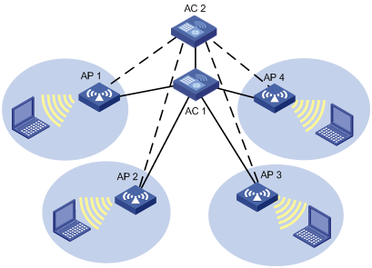
In the above figure, AC 1 is working in master mode and providing services to AP 1, AP 2, AP 3 and AP 4. AC 2 is working in slave mode. APs are connected to AC 2 through LWAPP slave tunnels. AC 1 and AC2 can be configured as backup for each other and should start master/slave detection. When AC 2 detects AC 1 is down, AC 2 will convert the work mode from slave to master. All APs which are connected to AC 2 through slave tunnels will transform the tunnels to master tunnels and use AC 2 as the master AC. Once AC 1 is reachable again, it will remain the backup.
Primary AC recovery
Figure 1-2 Primary AC recovery
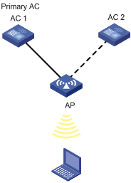
In the above figure, AC 1 acting as the primary AC is the master (which has the connection priority of 7), and it establishes a CAPWAP connection with the AP; AC 2 acts as the slave AC. If AC 1 goes down, AC 2 will act as the master until recovery of AC 1. This means once AC 1 is reachable again, the AP will establish a connection with AC 1 and disconnect from AC 2.
Dual work mode
Figure 1-3 Dual work mode
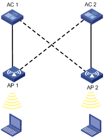
Dual work mode indicates that an AC can provide both master and slave connections. An AC will act as the master for some APs and act as the slave for some other APs. In the above scenario, AC 1 acts as the master for AP 1 and slave for AP 2. Similarly, AC 2 acts as the master for AP 2 and slave for AP 1.
Load Balancing
The load balancing parameters configured on the AC are used to determine whether the AC should accept or reject an association. Currently, the AC supports two types of load balancing, namely, AP load balancing and radio load balancing. Radio load balancing can be performed only if the AP load is not exceeding.
An AC does load balancing during the association of a client. It checks whether the load on the AP with which the client is attempting to connect exceeds the limit. If not, the current association is accepted. Otherwise, depending on the configuration, load balancing is carried out. As the result of load balancing, the current association request might be accepted or rejected.
Currently, the AC supports two modes of load balancing, the session mode and the traffic mode. When the session mode is configured, load balancing is done based on the number of users associated with the AP/radio. When the traffic mode is configured, traffic snapshot is considered for load balancing.
An AP sends periodic information about stations that are visible to it. The AC uses this neighbor information for load balancing.
In addition, when the AP/radio has exceeded the threshold, the AP/radio will stop responding to any probe request, thereby encouraging clients to associate with some other AP/radio.
As shown in Figure 1-4, a client is trying to connect with AP 1. But because AP 1’s load exceeds the threshold, it is connected with AP 2.
Figure 1-4 Load Balancing network diagram

Terminology
1) Threshold: Maximum number of users or maximum traffic rate. If both the threshold and the load gap are reached on an AP/radio, the AC will carry out load balancing.
2) Session mode: Load balancing mode in which the number of associated users is used to determine whether to perform load balancing.
3) Traffic Mode: Load balancing mode in which the amount of traffic is used to determine whether to perform load balancing.
4) Load gap: Maximum load gap between the radio/AP and the least loaded AP/radio. If both the threshold and the load gap are reached on an AP, the AC will perform load balancing.
AP load balancing
Load balancing is carried out on an AP either based on the number of users connected with it or based on the traffic load on it. The AP will start load balancing when the threshold and load gap are reached, and will reject any further associations until the load decreases below the threshold, a client is not able to associate with any other AP, or the load gap is less than the pre-defined limit.
Radio load balancing
Load balancing can be carried out on a radio only when its AP is not overloaded. A radio will start load balancing when the threshold and maximum load gap are reached and will reject any further associations until the load decreases below the threshold, a client is not able to associate with any other radio, or the load gap is less than the pre-defined limit.
Radio load balancing can be carried out only when all APs in the network are homogenous (all APs have the same number and type of radios).
Defense against DoS attacks
If a client resends an association request to an AP/radio n times, (n is the maximum number of retries), the AP/radio will accept the association to prevent DoS attacks on the client, even if the threshold and maximum load gap are reached.
This situation may occur when a station is not able to associate with any other AP other than the one it is currently trying to associate with. This kind of behavior may also arise due to station implementation.
Probe response masking
Some kinds of clients will not associate with any other AP even though the association request is rejected by the current AP, provided that the RSSI of the rejecting AP is more than other visible APs.
To avoid this, an AP/radio will not send probe responses once the threshold and maximum load gap are reached, thereby encouraging stations to associate with other APs. The AP/radio will respond to probe requests only when its load is below the limit. However, transmission of beacons is not controlled by load balancing.
AP Settings
A fit AP is a zero-configuration device. It can automatically discover an AC after power-on. To ensure that a fit AP can associate with an AC, their software versions must be consistent by default, which complicates maintenance. This task allows you designate the software version of an AP on the AC, so that they can associate with each other even if their software versions are inconsistent.
AP working mode switching: Switches the working mode of an AP between the FIT mode and the fat mode.
Configuring WLAN Advanced Settings
Setting a District Code
Select Advance > District Code from the navigation tree to enter the page for setting a district code, as shown in Figure 1-5.
Figure 1-5 Set a district code
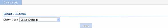
Table 1-1 shows the configuration item of setting a district code.
Table 1-1 Configuration item of setting a district code
|
Item |
Description |
|
District Code |
A district code determines characteristics such as the operating power level and total number of channels available for the transmission of frames. |
Configuring AC Backup
Configuring AC backup
Select Advance > AC Backup from the navigation tree to enter the page for configuring AC backup, as shown in Figure 1-6.
Figure 1-6 Configure AC backup
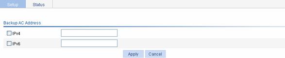
Table 1-2 shows the configuration items of configuring AC backup.
Table 1-2 Configuration items of configuring AC backup
|
Item |
Description |
|
IPv4 |
Select the IPv4 check box, and type the IPv4 address of the backup AC |
|
IPv6 |
Select the IPv6 check box, and type the IPv6 address of the backup AC |
Configuring Load Balancing
Configuring Session-mode load balancing
Select Advance > Load Balance from the navigation tree to enter the page for setting load balancing, and then select Session from the Loadbalance Mode drop-down list, as shown in Figure 1-7.
Figure 1-7 Set session-mode load balancing

Table 1-3 shows the configuration items of configuring session-mode load balancing.
Table 1-3 Configuration items of configuring session-mode load balancing
|
Item |
Description |
|
Loadbalance Mode |
Select Session. |
|
Threshold |
Load balancing is carried out for a radio when the session threshold and session gap threshold are exceeded. |
|
Gap |
Load balancing is carried out for a radio when the session threshold and session gap threshold are exceeded. |
Configuring Traffic-mode load balancing
Select Advance > Load Balance from the navigation tree to enter the page for setting load balancing, as shown in Figure 1-8.
Figure 1-8 Set traffic-mode load balancing

Table 1-4 shows the configuration items of configuring traffic-mode load balancing.
Table 1-4 Configuration items of configuring traffic-mode load balancing
|
Item |
Description |
|
Loadbalance Mode |
Select Traffic. |
|
Traffic |
Load balancing is carried out for a radio when the traffic threshold and traffic gap threshold are exceeded. |
|
Gap |
Load balancing is carried out for a radio when the traffic threshold and traffic gap threshold are exceeded. |
Configuring AP
Upgrading AP version
Select Advance > AP from the navigation tree, click the AP Module tab, select the desired AP, and then click Version Update to enter the page for AP version upgrade.
Table 1-5 shows the configuration items of AP upgrade.
Table 1-5 Configuration items of AP version upgrade
|
Item |
Description |
|
AP Model |
Displays the selected AP model. |
|
Software Version |
Type the software version in a correct format. |
Click Apply to complete AP software version upgrade.
Switch to fat AP
Select Advance > AP Setup from the navigation tree, select the Switch to Fat AP tab, select the desired AP, and then click Switch to Fat AP to perform AP working mode switchover.
Advanced Setting Configuration Examples
AC Backup Configuration Example
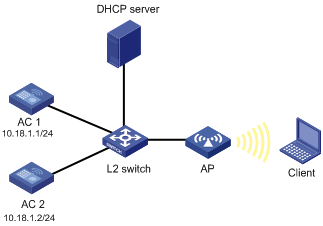
Network requirements
As shown in Figure 1-9, AC 1 and AC 2 are connected to a Layer 2 switch. An AP (serial ID SZ001) is connected to AC 1 and AC 2 through the L2 switch. AC 1, AC 2 and the AP are in the same network. The AP gets its IP address from the DHCP server. The IP address of AC 1 is 10.18.1.1 and the IP address of AC 2 is 10.18.1.2. AC 1 is working in master mode while AC 2 is working in slave mode. When AC 2 detects that AC 1 is down, AC 2 converts its work mode from slave to master. The AP that is connected to AC 2 through a slave tunnel will transform the tunnel mode to master and use AC 2 as the master AC.
Figure 1-9 AC backup configuration
2) Configuration on AC 1
# Configure AP, and establish a CAPWAP connection between AC 1 and AP.
For the related configuration, refer to Access Service in WLAN Service Configuration.
# Configure the IP address of the backup AC.
Select Advance > AC Backup from the navigation tree to enter the page for configuring the IP address of the backup AC, as shown in Figure 1-10.
Figure 1-10 Configure the IP address of the backup AC
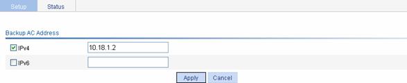
l Select the IPv4 checkbox, and set the IP address of the backup AC to 10.18.1.2.
l Click Apply.
3) Configuration on AC 2
# Configure AP, and establish a CAPWAP connection between AC 2 and AP.
For the related configuration, refer to Access Service in WLAN Service Configuration.
# Configure the IP address of the backup AC.
Select Advance > AC Backup from the navigation tree to enter the page for configuring the IP address of the backup AC, as shown in Figure 1-11.
Figure 1-11 Configure the address of the backup AC
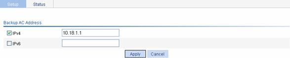
l Select the IPv6 check box, and set the address of the backup AC to 10.18.1.1.
l Click Apply.
Configuration guidelines
l The wireless services configured on the two ACs should be consistent.
l You can select Overview > AP or AP > AP Setup from the navigation tree to view the AP status, and you can see the AP status on the two ACs only after you configure the IP address of the AC.
l Specify the backup AC on each AC.
l AC backup has no relation with the access authentication method; however, the authentication method of the two ACs must be the same.
Session-Mode Load Balancing Configuration Example
Network requirements
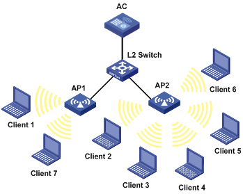
l As shown in Figure 1-12, all APs operate in 802.11g mode. Client 1 is associated with AP 1. Client 2 through Client 6 are associated with AP 2.
l Configure session-mode load balancing on the AC. The threshold, that is, the maximum number of sessions, is 5.
Figure 1-12 Network diagram for session-mode load balancing
Configuration procedure
1) Before configuring load balancing, complete the following:
l Ensure that the APs are associated with the AC. For the related configuration, refer to Access Service in WLAN Service Configuration.
l Ensure that the wireless clients can discover the APs.
2) Configure session-mode load balancing
Select Advance > Load Balance from the navigation tree on the left to enter the page for setting load balancing, as shown in Figure 1-13.
Figure 1-13 Set session-mode load balancing

l Select the Session mode.
l Type the threshold 5, and use the default value for the gap threshold.
l Click Apply.
Verfication
Client 1 is associated with AP1, and Client 2 through Client 6 are associated with AP2. Since the number of clients associated with AP1 reaches 5, and the load gap between AP2 and AP1 reaches 4, Client 7 is associated with AP1.
Configuration guidelines
Only when the number of clients associated with AP1 exceeds the session threshold and load gap does AP enable session-mode load balancing.
Traffic-Mode Load Balancing Configuration Example
Network requirements
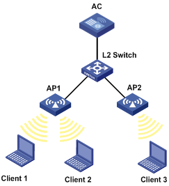
l As shown in Figure 1-14, all APs operate in 802.11g mode. Client 1 and Client 2 are associated with AP1.
l Configure traffic-mode load balancing on AC. The traffic threshold is 3 Mbps that corresponds to the threshold value of 10 in percentage.
Figure 1-14 Network diagram for traffic-mode load balancing
Configuration procedure
1) Before configuring load balancing, complete the following:
l Ensure that the APs are associated with the AC. For the related configuration, refer to Access Service in WLAN Service Configuration.
l Ensure that the wireless clients can discover the APs.
2) Configure traffic-mode load balancing
Select Advance > Load Balance from the navigation tree on the left to enter the page for setting load balancing, as shown in Figure 1-15.
Figure 1-15 Set traffic-mode load balancing

l Select the Traffic mode.
l Type the threshold 10, and the load gap 50.
l Click Apply.
Verfication
Client 1 and Client 2 are associated with AP 1. Add Client 3 to the network. Since the maximum traffic threshold and load gap are reached on AP 1, Client 3 is associated with AP 2.
Configuration guidelines
Only when the current traffic exceeds both the traffic threshold and load gap does AP enable traffic-mode load balancing.