- Table of Contents
-
- H3C WX Series Access Controllers Web-Based Configuration Manual-6PW103
- 00-1Cover
- 01-Quick Start
- 02-Web Overview
- 03-Summary
- 04-Device
- 05-Network
- 06-AP Configuration
- 07-WLAN Service Configuration
- 08-WLAN Roaming Configuration
- 09-Radio Configuration
- 10-Authentication
- 11-Security
- 12-QoS
- 13-SNMP
- 14-Advanced Settings
- Related Documents
-
| Title | Size | Download |
|---|---|---|
| 10-Authentication | 1.38 MB |
Table of Contents
Authentication Process of 802.1X
Implementation of 802.1X on Devices
Features Working Together with 802.1X
Displaying the Global 802.1X Information
Displaying the 802.1X Information of a Port
802.1X Configuration Guidelines
Introduction to Extended Portal Functions
Portal System Using the Local Portal Server
Configuring a Portal-Free Rule
Configuring the Local Portal Server
Configuring a Binding Between an SSID and an Authentication Page File
Customizing Authentication Pages
Configuring Authentication Methods for the ISP Domain
Configuring Authorization Methods for the ISP Domain
Configuring Accounting Methods for the ISP Domain
Configuring Local Authentication, Authorization, and Accounting for Telnet Users
Security and Authentication Mechanisms
Basic Message Exchange Process of RADIUS
RADIUS Configuration Guidelines
5 Local EAP Service Configuration
Local EAP Service Configuration Example (for WX5002 Only)
Requesting a Local Certificate
Retrieving and Displaying a CRL
Configuring a PKI Entity to Request a Certificate from a CA
l The sample Web page information in this manual was created on the WX5002. The Web page information on your device may vary.
l The models listed in this manual are not applicable to all regions. Please consult the local agents for the models applicable to your region.
When configuring authentication, go to these chapters for information you are interested in:
l Local EAP Service Configuration
802.1X Overview
The 802.1X protocol was proposed by the IEEE 802 LAN/WAN committee for security of wireless LANs (WLAN).It has been widely used on Ethernet as a common port access control mechanism.
Architecture of 802.1X
802.1X operates in the typical client/server model and defines three entities: supplicant system, authenticator system, and authentication server system, as shown in Figure 1-1.
Figure 1-1 Architecture of 802.1X
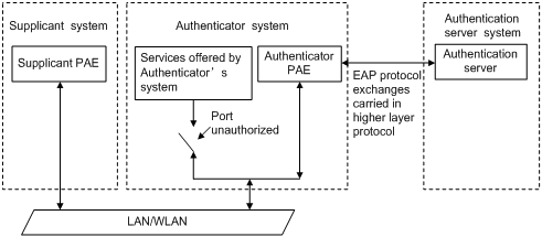
l Supplicant system: A system to be authenticated by the authenticator system residing on the same LAN. A supplicant system is usually a user-end device and initiates 802.1X authentication through 802.1X client software supporting the EAP over LANs (EAPOL) protocol.
l Authenticator system: The system that authenticates connected supplicant systems residing on the same LAN. An authenticator system is usually an 802.1X-enabled network device and provides ports (physical or logical) for supplicants to access the LAN.
l Authentication server system: The system providing authentication, authorization, and accounting services for the authenticator system. The authentication server, usually a Remote Authentication Dial-in User Service (RADIUS) server, maintains user information like username, password, and VLAN that the user belongs to.
The above systems involve three basic concepts: port access entity (PAE), controlled port, control direction.
PAE
PAE refers to the entity that performs the 802.1X algorithm and protocol operations.
l The authenticator PAE uses the authentication server to authenticate a supplicant trying to access the LAN and controls the status of the controlled port depending on the authentication result, putting the controlled port in the authorized state or unauthorized state. In authorized state, the port allows user data to pass, enabling the supplicant to access the network resources; while in unauthorized state, the port denies all data of the supplicant(s).
l The supplicant PAE responds to authentication requests of the authenticator PAE and provides authentication information. The supplicant PAE can also send authentication requests and logoff requests unsolicitedly to the authenticator.
Controlled port and uncontrolled port
An authenticator provides ports for supplicants to access the LAN. Each port can be regarded as a unity of two logical ports: a controlled port and an uncontrolled port.
l The uncontrolled port is always open in both the inbound and outbound directions to allow EAPOL protocol frames to pass, guaranteeing that the supplicant can always send and receive authentication frames.
l The controlled port is open to allow data traffic to pass only when it is in the authorized state.
The controlled port and uncontrolled port are two parts of the same port. Any frames arriving at the port are visible to both of them.
Control direction
In the unauthorized state, the controlled port can be set to deny traffic to and from the supplicant or just the traffic from the supplicant.
![]()
Currently, your device can only be set to deny traffic from the supplicant.
Operation of 802.1X
The 802.1X authentication system employs the Extensible Authentication Protocol (EAP) to exchange authentication information between the supplicant PAE, authenticator PAE, and authentication server.
Figure 1-2 Operation of 802.1X
![]()
l Between the supplicant PAE and authenticator PAE, EAP protocol packets are encapsulated using EAPOL and transferred over the LAN.
l Between the authenticator PAE and authentication server, EAP protocol packets can be handled in two modes: EAP relay and EAP termination. In EAP relay mode, EAP protocol packets are encapsulated by using the EAP over RADIUS and then relayed to the RADIUS server. In EAP termination mode, EAP protocol packets are terminated at the authenticator PAE, repackaged in the Password Authentication Protocol (PAP) or Challenge Handshake Authentication Protocol (CHAP) attributes of RADIUS packets, and then transferred to the RADIUS server.
l After a user passes the authentication, the authentication server passes information about the user to the authenticator, which then controls the status of the controlled port according to the instruction of the authentication server.
EAP over LANs
EAPOL frame format
EAPOL, defined in 802.1X, is intended to carry EAP protocol packets between supplicants and authenticators over LANs. Figure 1-3 shows the EAPOL frame format.
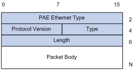
PAE Ethernet type: Protocol type. It takes the value 0x888E.
Protocol version: Version of the EAPOL protocol supported by the sender.
Type: Type of the EAPOL frame. Table 1-1 lists the types that the device currently supports.
Table 1-1 Types of EAPOL frames
|
Type |
Description |
|
EAP-Packet (a value of 0x00) |
Frame for carrying authentication information, present between an authenticator system and the authentication server. A frame of this type is repackaged and transferred by RADIUS to get through complex networks to reach the authentication server. |
|
EAPOL-Start (a value of 0x01) |
Frame for initiating authentication, present between a supplicant and an authenticator. |
|
EAPOL-Logoff (a value of 0x02) |
Frame for the logoff request, present between a supplicant and an authenticator. |
|
EAPOL-Key (a value of 0x03) |
Frame of key information, present between a supplicant and an authenticator. |
|
EAPOL-Encapsulated-ASF-Alert (a value of 0x04) |
Frame for supporting the Alerting message defined by Alert Standard Forum (ASF). It is used to encapsulate NMS-related information, such as alarm information, and terminated by the authenticator. |
Length: Length of the data, that is, length of the Packet body field, in bytes. If the value of this field is 0, no subsequent data field is present.
Packet body: Content of the packet. The format of this field depends on the value of the Type field.
EAP packet format
An EAP-Packet-type EAPOL frame carries an EAP packet in its Packet body field. The format of the EAP packet is shown in Figure 1-4.
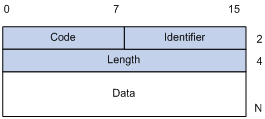
Code: Type of the EAP packet, which can be Request, Response, Success, or Failure.
l An EAP success/failure packet has no Data field, and has a length of 4.
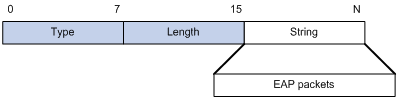
l An EAP Request/Response packet has a Data field in the format shown in Figure 1-5. The Type field indicates the EAP authentication type. A value of 1 represents Identity, indicating that the packet is for querying the identity of the supplicant. A value of 4 represents MD5-Challenge, which are similar to the PPP CHAP protocol.
Figure 1-5 Format of the Data field in an EAP request/response packet
![]()
Identifier: Helps match responses with requests.
Length: Length of the EAP packet, including the Code, Identifier, Length, and Data fields, in bytes.
Data: Content of the EAP packet. Its format is determined by the Code field.
EAP over RADIUS
Two attributes of RADIUS are intended for supporting EAP authentication: EAP-Message and Message-Authenticator. For information about RADIUS packet format, refer to RADIUS Configuration.
EAP-Message
The EAP-Message attribute is used to encapsulate EAP packets. Figure 1-6 shows its encapsulation format. The value of the Type field is 79. The String field can be up to 253 bytes long. If the EAP packet is longer than 253 bytes, it can be fragmented and encapsulated into multiple EAP-Message attributes.
Figure 1-6 Encapsulation format of the EAP-Message attribute
Message-Authenticator
Figure 1-7 shows the encapsulation format of the Message-Authenticator attribute. The Message-Authenticator attribute is used to prevent access requests from being snooped during EAP or CHAP authentication. It must be included in any packet with the EAP-Message attribute; otherwise, the packet will be considered invalid and discarded.
Figure 1-7 Encapsulation format of the Message-Authenticator attribute
![]()
Authentication Process of 802.1X
802.1X authentication can be initiated by either a supplicant or an authenticator system. A supplicant can initiate authentication by launching the 802.1X client software to send an EAPOL-Start frame to the authenticator system, while an authenticator system can initiate authentication by unsolicitedly sending an EAP-Request/Identity packet to an unauthenticated supplicant.
An 802.1X authenticator system communicates with a remote RADIUS server in two modes: EAP relay and EAP termination. The following description takes the EAP relay mode as an example to show the 802.1X authentication process.
EAP relay
EAP relay is an IEEE 802.1X standard mode. In this mode, EAP packets are carried in an upper layer protocol, such as RADIUS, so that they can go through complex networks and reach the authentication server. Generally, the EAP relay mode requires that the RADIUS server support the EAP attributes of EAP-Message and Message-Authenticator.
At present, the EAP relay mode supports four authentication methods: EAP-MD5, EAP-TLS (Transport Layer Security), EAP-TTLS (Tunneled Transport Layer Security), and PEAP (Protected Extensible Authentication Protocol).
l EAP-MD5: EAP-MD5 authenticates the identity of a supplicant. The RADIUS server sends an MD5 challenge (through an EAP-Request/MD5 Challenge packet) to the supplicant. Then the supplicant encrypts the password with the offered challenge.
l EAP-TLS: With EAP-TLS, a supplicant and the RADIUS server verify each other’s security certificates and identities, and guarantees that EAP packets are sent to the intended destination, thus preventing network traffic from being snooped.
l EAP-TTLS: EAP-TTLS extends EAP-TLS. EAP-TLS allows for mutual authentication between a supplicant and the authentication server. EAP-TTLS extends this implementation by transferring packets through the secure tunnels set up by TLS.
l PEAP: With PEAP, the RADIUS server establishes TLS tunnels with a supplicant system for integrity protection and then performs a new round of EAP negotiation with the supplicant system for identity authentication.
Figure 1-8 shows the message exchange procedure with EAP-MD5.
Figure 1-8 Message exchange in EAP relay mode
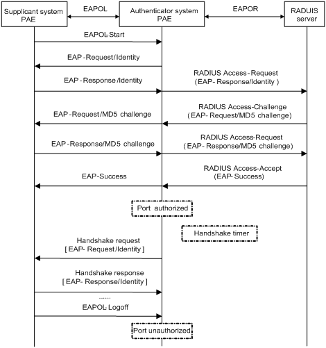
The following is how 802.1X authentication operates in EAP relay mode:
1) When a user launches the 802.1X client software and enters the registered username and password, the 802.1X client software generates an EAPOL-Start frame and sends it to the authenticator to initiate an authentication process.
2) Upon receiving the EAPOL-Start frame, the authenticator responds with an EAP-Request/Identity packet for the username of the supplicant.
3) When the supplicant receives the EAP-Request/Identity packet, it encapsulates the username in an EAP-Response/Identity packet and sends the packet to the authenticator. Upon receiving the EAP-Response/Identity packet, the authenticator relays the packet in a RADIUS Access-Request packet to the authentication server.
4) When receiving the RADIUS Access-Request packet, the RADIUS server compares the identify information against its user information table to obtain the corresponding password information. Then, it encrypts the password information using a randomly generated challenge, and sends the challenge information in a RADIUS Access-Challenge packet to the authenticator, which relays the contained EAP-Request/MD5 Challenge packet to the supplicant.
5) When receiving the EAP-Request/MD5 Challenge packet, the supplicant uses the offered challenge to encrypt the password part (this process is not reversible), creates an EAP-Response/MD5 Challenge packet, and then sends the packet to the authenticator, which then relays the packet in a RADIUS Access-Request packet to the authentication server.
6) When receiving the RADIUS Access-Request packet, the RADIUS server compares the password information encapsulated in the packet with that generated by itself. If the two are identical, the authentication server considers the user valid and sends to the authenticator a RADIUS Access-Accept and EAP-Success packet).
7) Upon receiving the RADIUS Access-Accept and EAP-Success packet), the authenticator opens the port to grant the access request of the supplicant. After the supplicant gets online, the authenticator periodically sends handshake requests to the supplicant to check whether the supplicant is still online. By default, if two consecutive handshake attempts end up with failure, the authenticator concludes that the supplicant has gone offline and changes the status of the port from authorized to unauthorized, guaranteeing that the authenticator always knows when a supplicant goes offline.
8) The supplicant can also send an EAPOL-Logoff frame to the authenticator to go offline unsolicitedly. In this case, the authenticator changes the status of the port from authorized to unauthorized.
![]()
In EAP relay mode, a supplicant must use the same authentication method as that of the RADIUS server, no matter which one of the above mentioned authentication methods is used. On the device, however, you only need to enable EAP relay.
EAP termination
In EAP termination mode, EAP packets are terminated at the authenticator and then repackaged into the PAP or CHAP attributes of RADIUS packets and transferred to the RADIUS server for authentication, authorization, and accounting. Figure 1-9 shows the basic message exchange procedure with CHAP authentication as example.
Figure 1-9 Message exchange in EAP termination mode
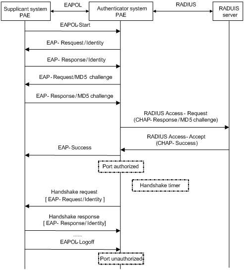
Different from the authentication process in EAP relay mode, it is the authenticator that generates the random challenge for encrypting the user password information in EAP termination authentication process. Consequently, the authenticator sends the challenge together with the username and encrypted password information from the supplicant to the RADIUS server for authentication.
802.1X Timers
This section describes the timers used on an 802.1X authenticator to guarantee that the supplicant, the authenticator, and the RADIUS server can interact with each other in a reasonable manner.
l Username request timeout timer (tx-period): The authenticator starts this timer when it sends an EAP-Request/Identity frame to a supplicant. If it receives no response before this timer expires, the authenticator retransmits the request. When cooperating with a supplicant that sends EAPOL-Start requests only when requested, the authenticator multicasts EAP-Request/Identity frames to the supplicant at an interval set by this timer.
l Supplicant timeout timer (supp-timeout): Once an authenticator sends an EAP-Request/MD5 Challenge frame to a supplicant, it starts this timer. If this timer expires but it receives no response from the supplicant, it retransmits the request.
l Server timeout timer (server-timeout): Once an authenticator sends a RADIUS Access-Request packet to the authentication server, it starts this timer. If this timer expires but it receives no response from the server, it retransmits the request.
l Handshake timer (handshake-period): After a supplicant passes authentication, the authenticator sends to the supplicant handshake requests at this interval to check whether the supplicant is online. If the authenticator receives no response after sending the allowed maximum number of handshake requests, it considers that the supplicant is offline.
l Quiet timer (quiet-period): When a supplicant fails the authentication, the authenticator refuses further authentication requests from the supplicant in this period of time.
Implementation of 802.1X on Devices
The devices extend and optimize the mechanism that the 802.1X protocol specifies by:
l Allowing multiple users to access network services through the same physical port.
l Supporting two authentication methods: macbased and portbased. With the macbased method, a port authenticates each connected user separately, and when an authenticated user goes offline, no other users are affected. With the portbased method, after the first user of a port passes authentication, all other users of the port can access the network without authentication, and when the first user goes offline, all other users get offline at the same time.
Features Working Together with 802.1X
VLAN assignment
After an 802.1X user passes the authentication, the server will send an authorization message to the device. If the server is enabled with the VLAN assignment function, the assigned VLAN information will be included in the message. The device, depending on the link type of the port connected to the supplicant, adds the port to the assigned VLAN according to the following rules:
l If the port link type is Access, the port leaves its current VLAN and joins the assigned VLAN.
l If the port link type is Trunk, the trunk port is added to the assigned VLAN. The default VLAN of the port is the assigned VLAN.
l If the port link type is Hybrid, the Hybrid port is added to the assigned VLAN without carrying the tag. The default VLAN of the port is the assigned VLAN.
The assigned VLAN neither changes nor affects the configuration of a port. However, as the assigned VLAN has higher priority than the user-configured VLAN, it is the assigned VLAN that takes effect for users passing authentication. After the user goes offline, the port returns to its original VLAN.
![]()
l For a Hybrid port, the VLAN assignment will fail if you have configured the assigned VLAN to carry tags.
l On a Hybrid port, you cannot configure an VLAN to carry tags after the VLAN has been assigned.
ACL assignment
Configuring 802.1X
Configuration Task List
802.1X provides a user identity authentication scheme. However, 802.1X cannot implement the authentication scheme solely by itself. RADIUS or local authentication must be configured to work with 802.1X.
l For remote RADIUS authentication, the username and password information must be configured on the RADIUS server.
l For local authentication, the username and password information must be configured on the authenticator and the service type must be set to LAN-access.
Table 1-2 lists the 802.1X configuration procedure.
Table 1-2 802.1X configuration procedure
|
Task |
Description |
|
Required Configure 802.1X on all ports By default, global 802.1X is disabled. |
|
|
Required Configure 802.1X on specified ports By default, 802.1X on a specific port is disabled. |
After the above configuration, you can view the 802.1X operation status on the Web interface to verify your configuration.
Table 1-3 Display 802.1X configuration
|
Task |
Description |
|
Display the global 802.1X configuration information, session information, and statistics information |
|
|
Display the 802.1X configuration information, session information, and statistics information on a port |
Configuring 802.1X Globally
From the navigation tree, select Authentication > 802.1x. Select the Global Setup tab to open the device setup page, as shown in Figure 1-10.
Figure 1-10 Global 802.1X configuration page
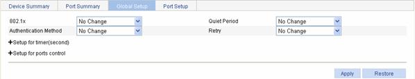
Table 1-4 lists global 802.1X configuration items.
Table 1-4 Global 802.1X configuration items
|
Item |
Description |
|
|
802.1x |
Specifies to enable or disable global 802.1X |
|
|
Quiet Period |
Specifies to enable or disable the quiet timer After an 802.1X user fails to be authenticated, the device will keep quiet for a period of time defined by the quiet timer. During the quiet period, the device will not perform 802.1X authentication on the user. |
|
|
Authentication Method |
Specifies the authentication method for 802.1X users The options include CHAP, PAP, and EAP. |
|
|
Retry: |
Specifies the maximum number of attempts to send an authentication request to a supplicant Within a specified period of time (defined by TX period or supplicant timeout below in this table), if the device does not receive the response from the supplicant, the device will determine whether to send an authentication request again according to the value defined by this parameter. 1 means that the device will send an authentication request only once even if it does not receive any response from the supplicant within the set interval. 2 means that the device will send an authentication request again if it does not receive any response from the supplicant within the set interval, and so forth. |
|
|
Setup for timer (second) |
TX Period |
Specifies the transmission interval |
|
Handshake Period |
Specifies the handshake interval |
|
|
Quiet Period |
Specifies the quiet timer interval |
|
|
Supplicant Timeout |
Specifies the supplicant timeout interval |
|
|
Server Timeout |
Specifies the server timeout interval |
|
|
Setup for ports control |
Port Control |
Specifies the 802.1X access control mode on all ports The options include: l Auto: The initial state on a port is unauthorized and becomes authorized when the authentication is successful. This mode is commonly applied. l Force-Authorized: A port is always in the authorized state. l Force-Unauthorized: A port is always in the unauthorized state. |
|
Port Method |
Specifies the 802.1X access method on all ports The options include: l MAC Based l Port Based |
|
|
Max Users |
Specifies the maximum number of users allowed on a port. To set this parameter, select the Max Users check box, and enter the desired value. |
|
Return to 802.1X configuration procedure.
Configuring 802.1X on a Port
From the navigation tree, select Authentication > 802.1x. Select the Port Setup tab to open the port setup page, as shown in Figure 1-11.
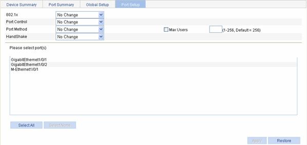
Table 1-5 lists port 802.1X configuration items.
Table 1-5 Port 802.1X configuration items
|
Item |
Description |
|
802.1x |
Specifies to enable or disable 802.1X on the specified port(s). |
|
Port Control |
Specifies the 802.1X access control mode on the specified port(s) The options include: l Auto: The initial state on a specified port is unauthorized and becomes authorized when the authentication is successful. This mode is commonly applied. l Force-Authorized: A specified port is always in the authorized state. l Force-Unauthorized: A specified port is always in the unauthorized state. |
|
Port Method |
Specifies the 802.1X port access control method on the specified port(s) The options include: l MAC Based l Port Based |
|
HandShake |
Specifies to enable or disable the online user handshake function, which is used by the device to periodically detect whether a user is still online. |
|
Max Users |
Specifies the maximum number of access users allowed on a specified port To specify this value, select the checkbox before Max Users. |
|
Please select port(s) |
Select one or multiple ports in the port list |
Return to 802.1X configuration procedure.
Displaying the Global 802.1X Information
From the navigation tree, select Authentication > 802.1x. The device summary page will appear, as shown in Figure 1-12. You can view the global 802.1X related information on this page.
Figure 1-12 Device 802.1X information page
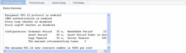
Return to Display 802.1X configuration.
Displaying the 802.1X Information of a Port
From the navigation tree, select Authentication > 802.1x. Select the Port Summary tab to open the port summary page, where you can view the 802.1X information of a port by selecting the port in the port list, as shown in Figure 1-13.
Figure 1-13 Port 802.1X information page
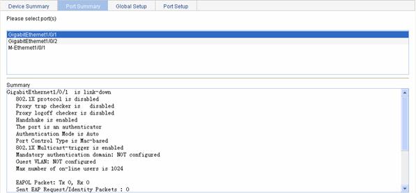
Return to Display 802.1X configuration.
802.1X Configuration Guidelines
When configuring 802.1X, note that:
1) 802.1X configuration on a specific port can take effect only after both global 802.1X and 802.1X on the specific port are enabled.
2) Do not change the timer parameters of global 802.1X from their default values unless you have determined that the changes would better the interaction process in some special network environment.
3) A port enabled with 802.1X cannot be added to an aggregation group. Meanwhile, it is prohibited to enable 802.1X on a port that belongs to an aggregation group.
4) For an 802.1X supplicant using Extensible Authentication Protocol (EAP) authentication, the authenticator directly encapsulates contents from the supplicant and sends them to the authentication server. In this scenario, the configuration on username format on the authenticator does not take effect. For details about username format configuration, refer to RADIUS Configuration.
5) If 802.1X multicast trigger function is enabled on a port, the port will periodically send multicast trigger packets to connected supplicants to initiate authentication. In a wireless LAN (WLAN), however, a supplicant can initiate authentication, or the wireless module initiates authentication after finding a supplicant. It is recommended to disable 802.1X multicast trigger function on the access device in a WLAN because multicast-trigger packets occupy wireless communication bandwidth.
6) The Voice VLAN and 802.1X functions are mutually exclusive on an access port if the connected supplicant sends untagged traffic.
2 Portal Configuration
Portal Overview
With portal authentication, an access device forces all users to log into the portal website at first. Every user can access the free services provided on the portal website; but to access the Internet, a user must pass portal authentication on the portal website.
A user can access a known portal website, enter username and password for authentication. This authentication mode is called active authentication. There is still another authentication mode, namely forced authentication, in which the access device forces a user trying to access the Internet through HTTP to log in to a portal website for authentication.
The portal feature provides the flexibility for Internet service providers (ISPs) to manage services. A portal website can, for example, present advertisements, and deliver community services and personalized services. In this way, broadband network providers, equipment providers, and content service providers form an industrial ecological system.
Introduction to Extended Portal Functions
By forcing users to implement patching and anti-virus policies, extended portal functions help users to defend against viruses. The main extended functions are described as follows:
l Security authentication mechanism: The security authentication mechanism works after the identity authentication process to check that the required anti-virus software, virus definition updates and OS patches are installed, and no unauthorized software is installed on the terminal of a user.
l Resource access limit: A user passing identity authentication can access only network resources like the anti-virus server or OS patch server, which are called the restricted resources. Only users passing security authentication can access more network resources, which are called the unrestricted resources.
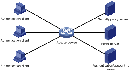
Portal System Components
As shown in Figure 2-1, a typical portal system consists of five basic components: authentication client, access device, portal server, authentication/accounting server, and security policy server.
![]()
A portal server can be an entity independent of the access device or an entity embedded in the access device. In this document, the term portal server refers to an independent portal server, and the term local portal server refers to an embedded one.
Figure 2-1 Portal system components
Authentication client
Client system of a user to be authenticated. It can be a browser using the Hypertext Transfer Protocol (HTTP), or a host running the portal client software. The security authentication of a client depends on the communications between the portal client and the security policy server.
Access device
Device for broadband access. It can be a switch or a router that provides the following three functions:
l Before authentication, redirecting all HTTP requests from users in the subnet to be authenticated to the portal server.
l During authentication, interacting with the portal server, security policy server and the authentication/accounting server for identity authentication, security authentication and accounting.
l After authentication, allowing users to access granted Internet resources.
Portal server
Server that listens to authentication requests from portal clients and exchanges client authentication information with the access device. It provides free portal services and a web-based authentication interface.
Authentication/accounting server
Server that implements user authentication and accounting through interaction with the access device.
Security policy server
Server that interacts with portal clients and access devices for security authentication and resource authorization.
The above five components interact in the following procedure:
1) When an unauthenticated user enters a website address in the address bar of the IE to access the Internet, an HTTP request is created and sent to the access device, which redirects the HTTP request to the web authentication homepage of the portal server. For extended portal functions, authentication clients must run the portal client.
2) On the authentication homepage/authentication dialog box, the user enters and submits the authentication information, which the portal server then transfers to the access device.
3) Upon receipt of the authentication information, the access device communicates with the authentication/accounting server for authentication and accounting.
4) After successful authentication, the access device checks whether there is corresponding security policy for the user. If not, it allows the user to access the Internet. Otherwise, the client, the access device and the security policy server communicates to perform security authentication of the user, and the security policy server authorizes the user to access resources depending on the security authentication result.
![]()
l Since a portal client uses an IP address as its ID, ensure that there is no Network Address Translation (NAT) device between the authentication client, access device, portal server, and authentication/accounting server when deploying portal authentication. This is to avoid authentication failure due to NAT operations.
l Currently, only a RADIUS server can serve as the authentication/accounting server in a portal system.
l Currently, security authentication requires the cooperation of the H3C iNode client.
Portal System Using the Local Portal Server
![]()
Support for this feature depends on the device model.
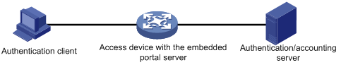
System components
In addition to use a separate device as the portal server, a portal system can also use the local portal server function of the access device to authenticate Web users directly. In this case, the portal system consists of only three components: authentication client, access device, and authentication/accounting server, as shown in Figure 2-2.
Figure 2-2 Portal system using the local portal server
![]()
l A portal system using the local portal server does not support extended portal functions. Therefore, there is no need to configure any security policy server for it.
l The local portal server function of the access device only implements some simple portal server functions, allowing users to log in and log out through the Web interface. It cannot completely take the place of an independent portal server.
Protocols used for interaction between client and local portal server
HTTP and HTTPS can be used for interaction between an authentication client and the access device providing the local portal server function. If HTTP is used, there are potential security problems because HTTP packets are transferred in plain text; if HTTPS is used, data security is ensured because HTTPS packets are transferred in ciphertext based on SSL.
Authentication page customization support
The local portal server function allows you to customize authentication pages. You can customize authentication pages by editing the corresponding HTML files and then compress and save the files to the storage medium of the device. Each set of customized authentication pages consists of six authentication pages: the logon page, the logon success page, the online page, the logoff success page, the logon failure page, and the system busy page. A local portal server will push a corresponding authentication page at each authentication phase.
![]()
l Authentication page customization applies to only wireless networking environments. For rules of customizing authentication pages, refer to Customizing Authentication Pages.
l As an access controller (AC) in wireless Layer 3 networking cannot get user SSIDs, the authentication system can only provide the default authentication pages.
Portal Authentication Modes
Portal authentication supports two modes: non-Layer 3 authentication and Layer 3 authentication.
Non-Layer 3 authentication
Non-Layer 3 authentication falls into two categories: direct authentication and Re-DHCP authentication.
l Direct authentication
Before authentication, a user manually configures an IP address or directly obtains a public IP address through DHCP, and can access only the portal server and predefined free websites. After passing authentication, the user can access the network resources. The process of direct authentication is simpler than that of re-DHCP authentication.
l Re-DHCP authentication
Before authentication, a user gets a private IP address through DHCP and can access only the portal server and predefined free websites. After passing authentication, the user is allocated a public IP address and can access the network resources. No public IP address is allocated to those who fails authentication. This solves the problem about IP address planning and allocation and proves to be useful. For example, a service provider can allocate public IP addresses to broadband users only when they access networks beyond the residential community network.
![]()
The local portal server function does not support re-DHCP authentication.
Layer 3 authentication
Layer 3 portal authentication is similar to direct authentication. However, in Layer-3 portal authentication mode, Layer 3 forwarding devices can be present between the authentication client and the access device.
Differences between Layer 3 and non-Layer 3 authentication modes
l Networking mode
From this point of view, the difference between these two authentication modes lies in whether or not a Layer 3 forwarding device can be present between the authentication client and the access device. The former supports Layer 3 forwarding devices, while the latter does not.
l User identifier
In Layer 3 authentication mode, a client is uniquely identified by an IP address. This is because the mode supports Layer 3 forwarding devices between the authentication client and the access device but the access device does not learn the MAC address of the authentication client. In non-Layer 3 authentication mode, a client is uniquely identified by the combination of its IP address and MAC address because the access device can learn the MAC address of the authentication client.
Due to the above differences, when the MAC address of an authentication client remains the same but the IP address changes, a new portal authentication will be triggered in Layer-3 authentication mode but will not be triggered in non-Layer 3 authentication mode. In non-Layer 3 authentication mode, a new portal authentication will be triggered only when both the MAC and IP address of the authentication client are changed.
Portal Authentication Process
Direct authentication and Layer 3 authentication share the same authentication process, while re-DHCP authentication has a different process because of the presence of two address allocation procedures.
Direct authentication/Layer 3 authentication process
Figure 2-3 Direct authentication/Layer 3 authentication process
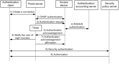
The direct authentication/Layer 3 authentication process is as follows:
2) A portal user initiates an authentication request through HTTP. When the HTTP packet arrives at the access device, the access device allows it to pass if it is destined for the portal server or a predefined free website, or redirects it to the portal server if it is destined for other websites. The portal server provides a web page for the user to enter the username and password.
3) The portal server and the access device exchange Challenge Handshake Authentication Protocol (CHAP) messages. For Password Authentication Protocol (PAP) authentication, this step is skipped.
4) The portal server assembles the username and password into an authentication request message and sends it to the access device. Meanwhile, the portal server starts a timer to wait for an authentication acknowledgment message.
5) The access device and the RADIUS server exchange RADIUS packets to authenticate the user.
6) If the user passes authentication, the access device sends an authentication acknowledgment message to the portal server.
7) The portal server sends an authentication acknowledgment message to the authentication client to notify it of logon success.
8) The portal server sends an affirmation message to the access device.
With extended portal functions, the process includes two additional steps:
9) The security policy server exchanges security authentication information with the client to check whether the authentication client meets the security requirements.
10) The security policy server authorizes the user to access unrestricted resources based on the security configuration for the user. The authorization information is stored on the access device and used by the access device to control user access.
Re-DHCP authentication process
Figure 2-4 Re-DHCP authentication process
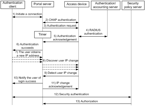
The re-DHCP authentication process is as follows:
Step 1 through step 6 are the same as those in the direct authentication/Layer 3 portal authentication process.
1) After receiving an authentication acknowledgment message, the authentication client obtains a new public IP address through DHCP and notifies the portal server that it has obtained a public IP address.
2) The portal server notifies the access device that the authentication client has obtained a new public IP address.
3) Detecting the change of the IP address by examining ARP packets received, the access device notifies the portal server of the change.
4) The portal server notifies the authentication client of logon success.
5) The portal server sends a user IP address change acknowledgment message to the access device.
With extended portal functions, the process includes two additional steps:
6) The security policy server exchanges security authentication information with the client to check whether the authentication client meets the security requirements.
7) The security policy server authorizes the user to access unrestricted resources based on the security configuration for the user. The authorization information is stored on the access device and used by the access device to take control of user access.
Authentication process with local portal server
Figure 2-5 Authentication process with local portal server
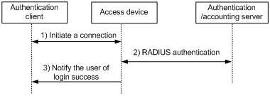
With local portal server, the direct/Layer 3 authentication process is as follows:
1) When a portal user accesses a web page, the authentication client initiates an authentication request through HTTP or HTTPS. When the HTTP or HTTPS packet arrives at an access device using the local portal server, it is redirected to the local portal server, which then provides a Web page for the user to enter the username and password for authentication.
2) The access device and the RADIUS server exchange RADIUS packets to authenticate the user.
3) If the user passes authentication, the local portal server pushes a logon success page to the authentication client, informing the user of the authentication (logon) success.
![]()
If HTTPS is used, after the portal user initiates an authentication request through HTTPS, the authentication client and the access device will first perform SSL negotiation to establish a secure path that encrypts packets to be transferred.
Configuring Portal
Configuration Prerequisites
The portal feature provides a solution for user authentication and security authentication. However, the portal feature cannot implement this solution by itself. Currently, RADIUS authentication needs to be configured on the access device to cooperate with the portal feature to complete user authentication.
The prerequisites for portal authentication are as follows:
l The portal-enabled interfaces of the access device are configured with valid IP addresses or have obtained valid IP addresses through DHCP.
l The portal server and the RADIUS server have been installed and configured properly. If you want to use the local portal server, no independent portal server is required.
l With re-DHCP authentication, the invalid IP address check function of DHCP relay is enabled on the access device, and the DHCP server is installed and configured properly.
l With RADIUS authentication, usernames and passwords of the users are configured on the RADIUS server, and the RADIUS client configurations are performed on the access device. For information about RADIUS client configuration, refer to RADIUS Configuration.
Configuration Task List
Perform the tasks in Table 2-1 to configure the portal function.
Table 2-1 Portal configuration task list
|
Task |
Remarks |
|
Required Configure portal server related parameters. By default, no portal server is configured. |
|
|
Required Apply the portal server to an interface and configure the portal authentication parameters. By default, no portal server is applied to an interface. |
|
|
Optional Configure a portal-free rule, specifying the source and destination information for packet filtering A portal-free rule allows specified users to access specified external websites without portal authentication. Packets matching a portal-free rule will not trigger portal authentication and the users can directly access the specified external websites. By default, no portal-free policy is configured. |
|
|
Required if local portal server is used. Configure and enable the local portal server and specify the protocol to be used for authentication information exchange between the client and the local portal server By default, the local portal server is disabled. |
|
|
Configuring a Binding Between an SSID and an Authentication Page File |
Optional Configure a binding between an SSID and an authentication page file. After such configuration, when a user accesses the portal page, the local portal server will provide authentication pages for the user according to the SSID of the user login interface and its bound authentication page file. By default, no SSID is bound to any authentication page file. |
Configuring a Portal Server
Select Authentication > Portal from the navigation tree. The portal server configuration page will appear, as shown in Figure 2-6. Click Add to enter the portal server configuration page.
Figure 2-6 Portal server configuration
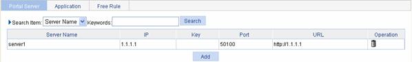
Table 2-2 describes the portal server configuration items.
Table 2-2 Portal server configuration items
|
Item |
Description |
|
Server-name |
Specify the portal server name. |
|
Server-IP |
Specify the IP address of the portal server. l To use an independent portal server, you need to specify the IP address of the independent portal server. l To use the local portal server of the access device, you need to type the IP address of a Layer 3 interface on the device in this field. Note that the specified interface must be reachable to the client. |
|
Key |
Specify the shared key to be used for communication between the device and the portal server.
When a local portal server is used, you can specify the shared key but it does not take effect. |
|
Port |
Specify the destination port number to be used by the device to send packets to the portal server unsolicitedly. The port number must be the same with that used by the remote portal server.
When a local portal server is used, you can specify the port number but it does not take effect. |
|
URL |
Specify the URL for HTTP packets redirection.
l Supports DNS, however, you need to configure a portal-free rule and add the DNS server address into the portal-free address range. l When a local portal server is used, you can specify the URL but it does not take effect. |
Return to Portal configuration task list.
Applying Portal Services
Select Authentication > Portal from the navigation tree, and then select the Application tab to enter the portal service application list page, as shown in Figure 2-7. Click Add to enter the page for applying portal services.
Figure 2-7 Portal service application list
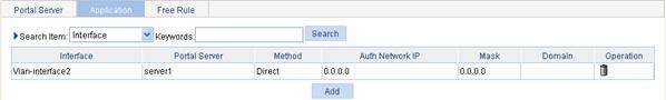
Table 2-3 describes configuration items for portal service application.
Table 2-3 Configuration items for applying portal services
|
Item |
Description |
|
Interface |
Specify the interface to be enabled with portal authentication. |
|
Portal-server |
Specify the portal server to be used. |
|
Method |
Specify the portal authentication mode, which can be: l Direct: Direct portal authentication l Layer3: Layer 3 portal authentication l Re-DHCP: Re-DHCP portal authentication
l In Layer-3 portal authentication mode, Layer 3 forwarding devices are not required to be present between the authentication client and the access device. However, if they are present, you must select the Layer 3 portal authentication mode. l In Re-DHCP portal authentication mode, the client is allowed to send out packets using a public IP address before it passes portal authentication. However, responses of the packets are restricted. l If the local portal server is used, you can configure the re-DHCP mode but it will not take effect. |
|
Auth-network-IP |
Specify the IP address and mask of the authentication subnet for Layer 3 portal authentication mode. By configuring an authentication subnet, you can specify that only packets from users on the authentication subnet trigger portal authentication. Packets that are neither from portal-free users nor from authentication subnet are discarded. You can configure an authentication subnet only when the Layer 3 portal authentication mode is used.
The authentication subnet in direct mode is any source IP address, and that in re-DHCP mode is the private subnet determined by the interface’s private IP address. |
|
Network-mask |
|
|
Specified-domain |
Specify the mandatory authentication domain. After you specify a mandatory authentication domain for an interface, the device will use the mandatory authentication domain for authentication, authorization, and accounting (AAA) of the portal users on the interface, ignoring the domain names carried in the usernames. Thereby, you can specify different authentication domains for different interfaces as needed. The available ISP domains can be specified in page you enter by selecting Authentication > AAA from the navigation tree Refer to AAA Configuration. |
Return to Portal configuration task list.
Configuring a Portal-Free Rule
Select Authentication > Portal from the navigation tree, and then select the Free Rule tab to enter the portal-free rule list page, as shown in Figure 2-8. Click Add to enter the page for adding a new portal-free rule.
Figure 2-8 Portal-free rule configuration
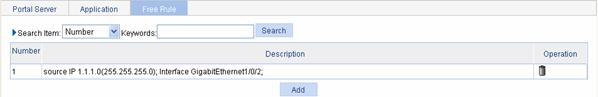
Table 2-4 describes the configuration items for adding a portal-free rule.
Table 2-4 Configuration items for adding a portal-free rule
|
Item |
Description |
|
Number |
Specify the sequence number of the portal-free rule. |
|
Source-interface |
Specify the source interface of the portal-free rule. The SSIDs in the drop-down list are the corresponding SSIDs of the wireless ESS interfaces. |
|
Source IP address |
Specify the source IP address and mask of the portal-free rule. |
|
Mask |
|
|
Source MAC |
Specify the source MAC address of the portal-free rule.
If you configure both the source IP address and the source MAC address, make sure that the mask of the specified source IP address is 255.255.255.255. Otherwise, the specified source MAC address will not take effect. |
|
Source-VLAN |
Specify the source VLAN of the portal-free rule.
If you configure both a source interface and a source VLAN for a portal-free rule, make sure that the source interface is in the source VLAN. Otherwise, the portal-free rule will not take effect. |
|
Destination IP Address |
Specify the destination IP address and mask of the portal-free rule. |
|
Mask |
Return to Portal configuration task list.
Configuring the Local Portal Server
Select Authentication > Local Portal from the navigation tree. The protocol configuration page will appear, as shown in Figure 2-9.
Figure 2-9 Protocol configuration page
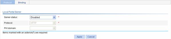
Table 2-5 describes the local portal server configuration items.
Table 2-5 Local portal server configuration items
|
Item |
Description |
|
Service status |
Enable or disable the local portal server function. You can configure the following items after you enable the local portal server. |
|
Protocol |
Specify the protocol to be used for authentication information exchange between the client and the local portal server. It can be HTTP or HTTPS. If you select HTTPS, you need to configure the PKI domain. |
|
PKI domain |
Specify the PKI domain for EAP authentication. The available PKI domains are those configured in the page you enter by selecting Authentication > PKI from the navigation tree. Refer to PKI Configuration.
l The service management, local portal authentication and local EAP service modules always reference the same PKI domain. Changing the referenced PKI domain in any of the three modules will also change that referenced in the other two modules. l All modules that need to use a PKI domain use the same PKI domain. To select a new PKI domain, you need to disable all these modules, enable them again, and then select a PKI domain for them. Otherwise, the new PKI domain does not take effect and the SSL module still uses the original PKI domain to retrieve certificates. |
Return to Portal configuration task list.
Configuring a Binding Between an SSID and an Authentication Page File
Select Authentication > Local Portal from the navigation tree. Click the Binding tab to enter the SSID-to-page file binding list, as shown in Figure 2-10. Click Add to enter to the page for binding an SSID with an authentication page file.
Figure 2-10 Authentication page customization
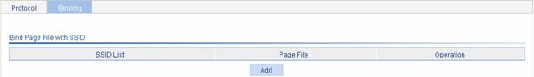
Table 2-6 describes configuration items for binding an SSID with an authentication page file.
Table 2-6 Configuration items for binding an SSID with an authentication page file
|
Item |
Description |
|
SSID |
Specify the SSID to be bound. |
|
Page-file |
Specify the authentication page file to be bound. You can edit the authentication page file as required and save it in the portal directory under the root directory of the access device. For rules of customizing authentication pages, refer to Customizing Authentication Pages. |
Return to Portal configuration task list.
Customizing Authentication Pages
When the local portal server is used for portal authentication, one of its tasks is to push authentication pages to users. You can define different authentication pages for wireless users in different WLANs. Customized authentication pages exist in the form of HTML files. You can compress them, upload them through FTP or TFTP to the access device, and save them in the portal directory under the root directory of the access device. A set of authentication pages include six main pages: the logon page, the logon success page, the logon failure page, the online page, the system busy page, and the logoff success page. If you define only some of them, the system will use the default authentication pages for the undefined ones.
For the local portal server to operate normally and steadily, you need to follow the following rules when customizing authentication pages:
Rules on file names
The main pages of the authentication pages have predefined file names, which cannot be changed. The following table lists the names.
Table 2-7 Main authentication page file names
|
Main authentication page |
File name |
|
Logon page |
logon.htm |
|
Logon success page |
logonSuccess.htm |
|
Logon failure page |
logonFail.htm |
|
Online page Pushed for online state notification |
online.htm |
|
System busy page Pushed when the system is busy or the user is in the logon process |
busy.htm |
|
Logoff success page |
logoffSuccess.htm |
![]()
You can define the names of the files other than the main page files.
Rules on page requests
The local portal server supports only Post and Get requests.
l Post requests are used when users submit username and password pairs, log on the system, and log off the system.
l Get requests allow no recursion. For example, if file Logon.htm includes contents that perform Get action on file ca.htm, file ca.htm cannot include any reference to file Logon.htm.
Rules on Post request attributes
1) Observe the following requirements when editing a form of an authentication page:
l An authentication page can have multiple forms, but there must be one and only one form whose action is logon.cgi. Otherwise, user information cannot be sent to the local portal server.
l The username attribute is fixed as PtUser, and the password attribute is fixed as PtPwd.
l Attribute PtButton is required to indicate the action that the user requests, which can be Logon or Logoff.
l A logon Post request must contain PtUser, PtPwd, and PtButton attributes.
l A logoff Post request must contain the PtButton attribute.
2) Authentication pages logon.htm and logonFail.htm must contain the logon Post request.
The following example shows part of the script in page logon.htm.
<form action=logon.cgi method = post >
<p>User name:<input type="text" name = "PtUser" style="width:160px;height:22px"
maxlength=64>
<p>Password :<input type="password" name = "PtPwd" style="width:160px;height:22px"
maxlength=32>
<p><input type=SUBMIT value="Logon" name = "PtButton" style="width:60px;">
</form>
3) Authentication pages logonSuccess.htm and online.htm must contain the logoff Post request.
The following example shows part of the script in page online.htm.
<form action=logon.cgi method = post >
<p><input type=SUBMIT value="Logoff" name="PtButton" style="width:60px;">
</form>
Rules on page file compression and saving
l A set of authentication page files must be compressed into a standard zip file. A zip file name is in the form of *****.zip, and can contain only letters, numerals, and underscores.
l These zip files can be transferred to the device through FTP or TFTP, and must be saved in the portal directory under the root directory of the device.
Rules on file size and contents
For the system to push customized authentication pages smoothly, you need comply with the following size and content requirements on authentication pages.
l The size of the zip file of each set of authentication pages, including the main authentication pages and the page elements, should be no more than 500 KB.
l The size of a single page, including the main authentication page and the page elements, should be no more than 50 KB before being compressed.
l Page elements are files that the authentication pages need to reference, for example, back.jpg on page Logon.htm. Page elements, such as HTML, JS, CSS, and pictures, can contain only static contents.
Portal Configuration Example
Network requirements
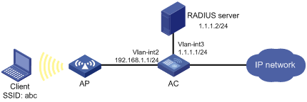
As shown in Figure 2-11:
l The wireless client accesses the network through the AP. The serial number of the AP is test.
l AC supports the local portal server, which runs HTTPS. The local portal server can push the corresponding customized pages according to the SSID of the user logon interface.
l A RADIUS server serves as the authentication/accounting server.
l The client must pass direct portal authentication to access unrestricted Internet resources. Before authentication, the client can access only the local portal server.
Figure 2-11 Configure direct portal authentication using the local portal server
Configuration procedure
![]()
Before performing portal configurations, be sure to:
l Configure IP addresses for the devices as shown in Figure 2-11 and ensure that routes are available between devices.
l Configure PKI domain test, and make sure that a local certificate and a CA certificate are obtained successfully. For details, refer to PKI Configuration.
l Complete the editing of the authentication page files to be bound with the client SSID.
Perform the following configurations on the AC:
1) Configure the RADIUS scheme system
# Specify the RADIUS authentication and accounting servers.
l From the navigation tree, select Authentication > RADIUS to enter the RADIUS server configuration page.
l Select Authentication Server as the server type.
l Enter the primary server IP address 1.1.1.2.
l Enter the primary server UDP port number 1812.
l Click Apply.
l Select Accounting Server as the server type.
l Enter the primary server IP address 1.1.1.2.
l Enter the primary server UDP port number 1813.
l Click Apply to finish the operation.
# Configure the scheme used for communication between the device and the RADIUS servers as follows:
l Select the RADIUS Setup tab to enter the RADIUS parameter configuration page.
l Select extended as the server type.
l Select the Authentication Server Shared Key checkbox, and enter expert in the textbox.
l Enter expert again in the Confirm Authentication Shared Key textbox.
l Select the Accounting Server Shared Key checkbox, and enter expert in the textbox.
l Enter expert again in the Confirm Accounting Shared Key textbox.
l Select without-domain as the username format.
l Click Apply to finish the operation.
2) Configure AAA
# Create an ISP domain.
l From the navigation tree, select Authentication > AAA. The domain setup page is displayed by default.
l Enter test in the Domain Name textbox.
l Select Enable to use it as the default domain.
l Click Apply to finish the operation.
# Configure an authentication, authorization, and accounting (AAA) schemes for the ISP domain.
l Select the Authentication tab.
l Select the domain name test.
l Select the Default AuthN checkbox and then select RADIUS as the authentication mode.
l Select system from the Name drop-down list to use it as the authentication scheme
l Click Apply.
l Select the Authorization tab.
l Select the domain name test.
l Select the Default AuthZ checkbox and then select RADIUS as the authorization mode.
l Select system from the Name drop-down list to use it as the authorization scheme
l Click Apply.
l Select the Accounting tab.
l Select the domain name test.
l Select the Accounting Optional checkbox, and then select Enable for this parameter.
l Select the Default Accounting checkbox and then select RADIUS as the accounting mode.
l Select system from the Name drop-down list to use it as the accounting scheme
l Click Apply.
3) Configure portal authentication
# Configure the local portal server.
l From the navigation tree select Authentication > Local Portal. The protocol configuration page is displayed by default.
l Select Enabled as the status of the local portal server.
l Select HTTPS as the protocol type.
l Select test as the PKI domain.
l Click Apply.
# Bind the client SSID with the customized authentication page file. (This configuration is optional. If you do not configure the binding, the system will provide the default authentication pages.)
l Select the Binding tab and then click the Add button.
l Select SSID abc.
l Select authentication page file ssid1.zip.
l Click Apply.
# Configure the portal server.
l From the navigation tree, select Authentication > Portal. The portal server configuration page is displayed by default.
l Enter the server name newpt.
l Enter the server IP address: 192.168.1.1.
l Click Apply.
# Apply portal services to the interface connecting the AP.
l Select the Application tab, and then click the Add button.
l Select interface Vlan-interface2.
l Select portal server newpt.
l Select authentication method Direct.
l Click Apply.
Verfiy the configuration
When accessing network segment 1.1.1.0/24, a user on the client should be redirected to page https://192.168.1.1/portal/logon.htm and, after entering the correct username and password on the Web page, pass the authentication.
3 AAA Configuration
AAA Overview
Introduction to AAA
Authentication, Authorization, and Accounting (AAA) provides a uniform framework for configuring these three security functions to implement network security management.
AAA usually uses a client/server model, where the client runs on the network access server (NAS) and the server maintains user information centrally. In an AAA network, a NAS is a server for users but a client for the AAA servers, as shown in Figure 3-1.
Figure 3-1 AAA networking diagram
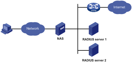
When a user tries to establish a connection to the NAS and to obtain the rights to access other networks or some network resources, the NAS authenticates the user or the corresponding connection. The NAS takes the responsibility to transparently pass the user’s AAA information to the server (RADIUS server). The RADIUS protocol defines how a NAS and a server exchange user information between them.
In the AAA network shown in Figure 3-1, there are two RADIUS servers. You can determine which of the authentication, authorization and accounting functions should be assumed by which servers. For example, you can use RADIUS server 1 for authentication and authorization, and RADIUS server 2 for accounting.
The three security functions are described as follows:
l Authentication: Identifies remote users and judges whether a user is legal.
l Authorization: Grants different users different rights. For example, a user logging into the server can be granted the permission to access and print the files in the server.
l Accounting: Records all network service usage information of users, including the service type, start and end time, and traffic. In this way, accounting can be used for not only charging, but also network security surveillance.
You can use AAA to provide only one or two security functions, if desired. For example, if your company only wants employees to be authenticated before they access specific resources, you only need to configure an authentication server. If network usage information is expected to be recorded, you also need to configure an accounting server.
As described above, AAA provides a uniform framework to implement network security management. It is a security mechanism that enables authenticated and authorized entities to access specific resources and records operations of the entities. As the AAA framework allows for excellent scalability and centralized user information management, it has gained wide application.
AAA can be implemented through multiple protocols. The RADIUS protocol is the most frequently used one in practice. Currently, the device supports using RADIUS for AAA. For details about RADIUS, refer to RADIUS Configuration.
Introduction to ISP Domain
An Internet service provider (ISP) domain represents a group of users. For a username in the userid@isp-name format, the access device considers the userid part the username for authentication and the isp-name part the ISP domain name.
In a networking scenario with multiple ISPs, an access device may connect users of different ISPs. As users of different ISPs may have different user attributes (such as username and password structure, service type, and rights), you need to configure ISP domains to distinguish the users. In addition, you need to configure different attribute sets including AAA methods for the ISP domains.
For the NAS, each user belongs to an ISP domain. If a user does not provide the ISP domain name, the system considers that the user belongs to the default ISP domain.
Configuring AAA
Configuration Prerequisites
1) To deploy local authentication, you need to configure local users on the access device. Refer to User Configuration.
2) To deploy remote authentication, authorization, or accounting, you need to create the RADIUS schemes to be referenced. For details about RADIUS, refer to RADIUS Configuration.
Configuration Task List
Perform the tasks in Table 3-1 to configure AAA.
Table 3-1 AAA configuration task list
|
Task |
Remarks |
|
|
Optional Create ISP domains and specify one of them as the default ISP domain. By default, there is an ISP domain named system, which is the default ISP domain. |
||
|
Optional Configure authentication methods for various types of users. By default, all types of users use local authentication. |
AAA user types include LAN access users (such as 802.1X authentication users and MAC authentication users), login users (such as SSH, Telnet, FTP, terminal access users), PPP users, Portal users, and Command users. |
|
|
Optional Specify the authorization methods for various types of users. |
||
|
Required Specify the accounting methods for various types of users. By default, all types of users use local accounting. |
||
Configuring an ISP Domain
Select Authentication > AAA from the navigation tree. The Domain Setup page appears, as shown in Figure 3-2.
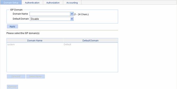
Table 3-2 describes the configuration items for creating an ISP domain.
Table 3-2 ISP domain configuration items
|
Item |
Description |
|
Domain Name |
Type the ISP domain name, which is for identifying the domain. You can type a new domain name to create a domain, or specify an existing domain to change its status (whether it is the default domain). |
|
Default Domain |
Specify whether to use the ISP domain as the default domain. l Enable: Uses the domain as the default domain. l Disable: Uses the domain as a non-default domain. There can only be one default domain at a time. If you specify a second domain as the default domain, the original default domain will become a non-default domain. |
Return to Configuration Task List.
Configuring Authentication Methods for the ISP Domain
Select Authentication > AAA from the navigation tree and then select the Authentication tab to enter the authentication method configuration page, as shown in Figure 3-3.
Figure 3-3 Authentication method configuration page
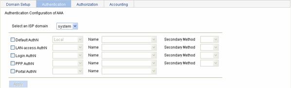
Table 3-3 describes the configuration items for specifying the authentication methods for an ISP domain.
Table 3-3 Authentication method configuration items
|
Item |
Description |
|
Select an ISP domain |
Select the ISP domain for which you want to specify authentication methods. |
|
Default AuthN |
Configure the default authentication method and secondary authentication method for all types of users. Options include: l HWTACACS: Performs HWTACACS authentication. You need to specify the HWTACACS scheme to be used. l Local: Performs local authentication. l None: All users are trusted and no authentication is performed. Generally, this mode is not recommended. l RADIUS: Performs RADIUS authentication. You need to specify the RADIUS scheme to be used. l Not Set: Restore the default, that is, local authentication. |
|
Name |
|
|
Secondary Method |
|
|
LAN-access AuthN |
Configure the authentication method and secondary authentication method for LAN access users. Options include: l Local: Performs local authentication. l None: All users are trusted and no authentication is performed. Generally, this mode is not recommended. l RADIUS: Performs RADIUS authentication. You need to specify the RADIUS scheme to be used. l Not Set: Uses the default authentication methods. |
|
Name |
|
|
Secondary Method |
|
|
Login AuthN |
Configure the authentication method and secondary authentication method for login users. Options include: l HWTACACS: Performs HWTACACS authentication. You need to specify the HWTACACS scheme to be used. l Local: Performs local authentication. l None: All users are trusted and no authentication is performed. Generally, this mode is not recommended. l RADIUS: Performs RADIUS authentication. You need to specify the RADIUS scheme to be used. l Not Set: Uses the default authentication methods. |
|
Name |
|
|
Secondary Method |
|
|
PPP AuthN |
Configure the authentication method and secondary authentication method for PPP users. Options include: l HWTACACS: Performs HWTACACS authentication. You need to specify the HWTACACS scheme to be used. l Local: Performs local authentication. l None: All users are trusted and no authentication is performed. Generally, this mode is not recommended. l RADIUS: Performs RADIUS authentication. You need to specify the RADIUS scheme to be used. l Not Set: Uses the default authentication methods. |
|
Name |
|
|
Secondary Method |
|
|
Portal AuthN |
Configure the authentication method for PPP users. Options include: l None: All users are trusted and no authentication is performed. Generally, this mode is not recommended. l RADIUS: Performs RADIUS authentication. You need to specify the RADIUS scheme to be used. l Not Set: Uses the default authentication methods. |
|
Name |
Return to Configuration Task List.
Configuring Authorization Methods for the ISP Domain
Select Authentication > AAA from the navigation tree and then select the Authorization tab to enter the authorization method configuration page, as shown in Figure 3-4.
Figure 3-4 Authorization method configuration page
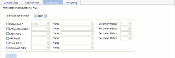
Table 3-4 describes the configuration items for configuring the authorization methods for an ISP domain.
Table 3-4 Authorization method configuration items
|
Item |
Description |
|
Select an ISP domain |
Select the ISP domain for which you want to specify authentication methods. |
|
Default AuthZ |
Configure the default authorization method and secondary authorization method for all types of users. Options include: l HWTACACS: Performs HWTACACS authorization. You need to specify the HWTACACS scheme to be used. l Local: Performs local authorization. l None: All users are trusted and authorized. A user gets the corresponding default rights of the system. l RADIUS: Performs RADIUS authorization. You need to specify the RADIUS scheme to be used. l Not Set: Restore the default, that is, local authorization. |
|
Name |
|
|
Secondary Method |
|
|
LAN-access AuthZ |
Configure the authorization method and secondary authorization method for LAN access users. Options include: l Local: Performs local authorization. l None: All users are trusted and authorized. A user gets the corresponding default rights of the system. l RADIUS: Performs RADIUS authorization. You need to specify the RADIUS scheme to be used. l Not Set: Uses the default authorization methods. |
|
Name |
|
|
Secondary Method |
|
|
Login AuthZ |
Configure the authorization method and secondary authorization method for login users. Options include: l HWTACACS: Performs HWTACACS authorization. You need to specify the HWTACACS scheme to be used. l Local: Performs local authorization. l None: All users are trusted and authorized. A user gets the corresponding default rights of the system. l RADIUS: Performs RADIUS authorization. You need to specify the RADIUS scheme to be used. l Not Set: Uses the default authorization methods. |
|
Name |
|
|
Secondary Method |
|
|
PPP AuthZ |
Configure the authorization method and secondary authorization method for PPP users. Options include: l HWTACACS: Performs HWTACACS authorization. You need to specify the HWTACACS scheme to be used. l Local: Performs local authorization. l None: All users are trusted and authorized. A user gets the corresponding default rights of the system. l RADIUS: Performs RADIUS authorization. You need to specify the RADIUS scheme to be used. l Not Set: Uses the default authorization methods. |
|
Name |
|
|
Secondary Method |
|
|
Portal AuthZ |
Configure the authorization method for PPP users. Options include: l None: All users are trusted and authorized. A user gets the corresponding default rights of the system. l RADIUS: Performs RADIUS authorization. You need to specify the RADIUS scheme to be used. l Not Set: Uses the default authorization methods. |
|
Name |
|
|
Command AuthZ |
Configure the authorization method for command users. Options include: l HWTACACS: Performs HWTACACS authorization. You need to specify the HWTACACS scheme to be used. l Not Set: Uses the default authorization methods. |
|
Name |
Return to Configuration Task List.
Configuring Accounting Methods for the ISP Domain
Select Authentication > AAA from the navigation tree and then select the Accounting tab to enter the accounting method configuration page, as shown in Figure 3-5.
Figure 3-5 Accounting method configuration page
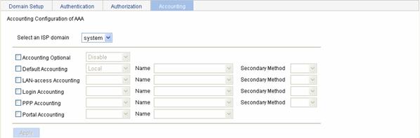
Table 3-5 describes the configuration items for configuring the accounting methods for an ISP domain.
Table 3-5 Accounting method configuration items
|
Item |
Description |
|
Select an ISP domain |
Select the ISP domain for which you want to specify authentication methods. |
|
Accounting Optional |
Specify whether to enable the accounting optional feature. l With the feature enabled, a user that will be disconnected otherwise can use the network resources even when there is no accounting server available or communication with the current accounting server fails. This feature applies to scenarios where authentication is required but accounting is not. l If accounting for such a user fails, the device will not send real-time accounting updates for the user any more. |
|
Default Accounting |
Configure the default accounting method and secondary accounting method for all types of users. Options include: l HWTACACS: Performs HWTACACS accounting. You need to specify the HWTACACS scheme to be used. l Local: Performs local accounting. l None: Performs no accounting. l RADIUS: Performs RADIUS accounting. You need to specify the RADIUS scheme to be used. l Not Set: Restore the default, that is, local accounting. |
|
Name |
|
|
Secondary Method |
|
|
LAN-access Accounting |
Configure the accounting method and secondary accounting method for LAN access users. Options include: l Local: Performs local accounting. l None: Performs no accounting. l RADIUS: Performs RADIUS accounting. You need to specify the RADIUS scheme to be used. l Not Set: Uses the default accounting methods. |
|
Name |
|
|
Secondary Method |
|
|
Login Accounting |
Configure the accounting method and secondary accounting method for login users. Options include: l HWTACACS: Performs HWTACACS accounting. You need to specify the HWTACACS scheme to be used. l Local: Performs local accounting. l None: Performs no accounting. l RADIUS: Performs RADIUS accounting. You need to specify the RADIUS scheme to be used. l Not Set: Uses the default accounting methods. |
|
Name |
|
|
Secondary Method |
|
|
PPP Accounting |
Configure the accounting method and secondary accounting method for PPP users. Options include: l HWTACACS: Performs HWTACACS accounting. You need to specify the HWTACACS scheme to be used. l Local: Performs local accounting. l None: Performs no accounting. l RADIUS: Performs RADIUS accounting. You need to specify the RADIUS scheme to be used. l Not Set: Uses the default accounting methods. |
|
Name |
|
|
Secondary Method |
|
|
Portal Accounting |
Configure the accounting method for PPP users. Options include: l None: Performs no accounting. l RADIUS: Performs RADIUS accounting. You need to specify the RADIUS scheme to be used. l Not Set: Uses the default accounting methods. |
|
Name |
Return to Configuration Task List.
AAA Configuration Example
Configuring Local Authentication, Authorization, and Accounting for Telnet Users
Network requirements
As shown in Figure 3-6, configure AC to perform local authentication, authorization, and accounting for Telnet users.
Figure 3-6 Configure local authentication, authorization, and accounting for Telnet users
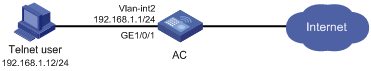
Configuration procedure
![]()
Enable the Telnet server function, and configure the AC to use AAA for Telnet user authentication. The configuration steps are omitted.
# Configure IP addresses for the interfaces. (Omitted)
# Configuring a local user
l Select Authentication > Users from the navigation tree. The Local User page appears. Click Add.
l Enter telnet as the username.
l Select telnet as the service type.
l Enter abcd as the password.
l Enter abcd to confirm the password.
l Click Apply.
# Configure the ISP domain to use local authentication.
l Select Authentication > AAA from the navigation tree and then select the Authentication tab.
l Select the domain system.
l Select the Login AuthN check box and select the authentication method Local.
l Click Apply.
# Configure the ISP domain to use local authorization.
l Select Authentication > AAA from the navigation tree and then select the Authentication tab.
l Select the domain system.
l Select the Login AuthZ check box and select the authorization method Local.
l Click Apply.
# Configure the ISP domain to use local accounting.
l Select Authentication > AAA from the navigation tree and then select the Accounting tab.
l Select the domain system.
l Select the Login Accounting check box and select the accounting method Local.
l Click Apply.
Now, if you telnet to the device and enter username telnet@system and password abcd, you should be serviced as a user in domain system.
4 RADIUS Configuration
RADIUS Overview
Remote Authentication Dial-In User Service (RADIUS) is protocol for implementing Authentication, Authorization, and Accounting (AAA). For details about AAA, refer to AAA Configuration.
Introduction to RADIUS
RADIUS is a distributed information interaction protocol using the client/server model. RADIUS can protect networks against unauthorized access and is often used in network environments where both high security and remote user access are required. RADIUS uses UDP, and its packet format and message transfer mechanism are based on UDP. It uses UDP port 1812 for authentication and 1813 for accounting.
RADIUS was originally designed for dial-in user access. With the diversification of access methods, RADIUS has been extended to support more access methods, for example, Ethernet access and ADSL access. It uses authentication and authorization in providing access services and uses accounting to collect and record usage information of network resources.
Client/Server Model
l Client: The RADIUS client runs on the NASs located throughout the network. It passes user information to designated RADIUS servers and acts on the responses (for example, rejects or accepts user access requests).
l Server: The RADIUS server runs on the computer or workstation at the network center and maintains information related to user authentication and network service access. It listens to connection requests, authenticates users, and returns the processing results (for example, rejecting or accepting the user access request) to the clients.
In general, the RADIUS server maintains three databases, namely, Users, Clients, and Dictionary, as shown in Figure 4-1.
Figure 4-1 RADIUS server components
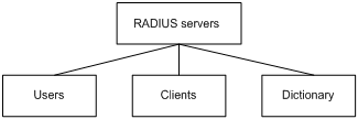
l Users: Stores user information such as the usernames, passwords, applied protocols, and IP addresses.
l Clients: Stores information about RADIUS clients, such as the shared keys and IP addresses.
l Dictionary: Stores information about the meanings of RADIUS protocol attributes and their values.
Security and Authentication Mechanisms
Information exchanged between a RADIUS client and the RADIUS server is authenticated with a shared key, which is never transmitted over the network. This enhances the information exchange security. In addition, to prevent user passwords from being intercepted on insecure networks, RADIUS encrypts passwords before transmitting them.
A RADIUS server supports multiple user authentication methods, for example, the Password Authentication Protocol (PAP) and Challenge Handshake Authentication Protocol (CHAP) of the Point-to-Point Protocol (PPP). Moreover, a RADIUS server can act as the client of another AAA server to provide authentication proxy services.
Basic Message Exchange Process of RADIUS
Figure 4-2 illustrates the interaction of the host, the RADIUS client, and the RADIUS server.
Figure 4-2 Basic message exchange process of RADIUS
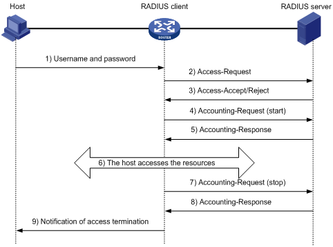
The following is how RADIUS operates:
1) The host initiates a connection request carrying the username and password to the RADIUS client.
2) Having received the username and password, the RADIUS client sends an authentication request (Access-Request) to the RADIUS server, with the user password encrypted by using the Message-Digest 5 (MD5) algorithm and the shared key.
3) The RADIUS server authenticates the username and password. If the authentication succeeds, it sends back an Access-Accept message containing the user’s authorization information. If the authentication fails, it returns an Access-Reject message.
4) The RADIUS client permits or denies the user according to the returned authentication result. If it permits the user, it sends a start-accounting request (Accounting-Request) to the RADIUS server.
5) The RADIUS server returns a start-accounting response (Accounting-Response) and starts accounting.
6) The user accesses the network resources.
7) The host requests the RADIUS client to tear down the connection and the RADIUS client sends a stop-accounting request (Accounting-Request) to the RADIUS server.
8) The RADIUS server returns a stop-accounting response (Accounting-Response) and stops accounting for the user.
9) The user stops access to network resources.
RADIUS Packet Format
RADIUS uses UDP to transmit messages. It ensures the smooth message exchange between the RADIUS server and the client through a series of mechanisms, including the timer management mechanism, retransmission mechanism, and slave server mechanism. Figure 4-3 shows the RADIUS packet format.
Figure 4-3 RADIUS packet format
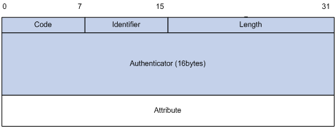
Descriptions of the fields are as follows:
1) The Code field (1-byte long) is for indicating the type of the RADIUS packet. Table 4-1 gives the possible values and their meanings.
Table 4-1 Main values of the Code field
|
Code |
Packet type |
Description |
|
1 |
Access-Request |
From the client to the server. A packet of this type carries user information for the server to authenticate the user. It must contain the User-Name attribute and can optionally contain the attributes of NAS-IP-Address, User-Password, and NAS-Port. |
|
2 |
Access-Accept |
From the server to the client. If all the attribute values carried in the Access-Request are acceptable, that is, the authentication succeeds, the server sends an Access-Accept response. |
|
3 |
Access-Reject |
From the server to the client. If any attribute value carried in the Access-Request is unacceptable, the server rejects the user and sends an Access-Reject response. |
|
4 |
Accounting-Request |
From the client to the server. A packet of this type carries user information for the server to start/stop accounting for the user. It contains the Acct-Status-Type attribute, which indicates whether the server is requested to start the accounting or to end the accounting. |
|
5 |
Accounting-Response |
From the server to the client. The server sends to the client a packet of this type to notify that it has received the Accounting-Request and has correctly started recording the accounting information. |
2) The Identifier field (1-byte long) is for matching request packets and response packets and detecting retransmitted request packets. The request and response packets of the same type have the same identifier.
3) The Length field (2-byte long) indicates the length of the entire packet, including the Code, Identifier, Length, Authenticator, and Attribute fields. The value of the field is in the range 20 to 4096. Bytes beyond the length are considered the padding and are neglected upon reception. If the length of a received packet is less than that indicated by the Length field, the packet is dropped.
4) The Authenticator field (16-byte long) is used to authenticate replies from the RADIUS server, and is also used in the password hiding algorithm. There are two kinds of authenticators: request authenticator and response authenticator.
5) The Attribute field, with a variable length, carries the specific authentication, authorization, and accounting information for defining configuration details of the request or response. This field is represented in triplets of Type, Length, and Value.
l Type: One byte, in the range 1 to 255. It indicates the type of the attribute. Commonly used attributes for RADIUS authentication, authorization and accounting are listed in Table 4-2.
l Length: One byte for indicating the length of the attribute in bytes, including the Type, Length, and Value fields.
l Value: Value of the attribute, up to 253 bytes. Its format and content depend on the Type and Length fields.
|
No. |
Attribute |
No. |
Attribute |
|
1 |
User-Name |
45 |
Acct-Authentic |
|
2 |
User-Password |
46 |
Acct-Session-Time |
|
3 |
CHAP-Password |
47 |
Acct-Input-Packets |
|
4 |
NAS-IP-Address |
48 |
Acct-Output-Packets |
|
5 |
NAS-Port |
49 |
Acct-Terminate-Cause |
|
6 |
Service-Type |
50 |
Acct-Multi-Session-Id |
|
7 |
Framed-Protocol |
51 |
Acct-Link-Count |
|
8 |
Framed-IP-Address |
52 |
Acct-Input-Gigawords |
|
9 |
Framed-IP-Netmask |
53 |
Acct-Output-Gigawords |
|
10 |
Framed-Routing |
54 |
(unassigned) |
|
11 |
Filter-ID |
55 |
Event-Timestamp |
|
12 |
Framed-MTU |
56-59 |
(unassigned) |
|
13 |
Framed-Compression |
60 |
CHAP-Challenge |
|
14 |
Login-IP-Host |
61 |
NAS-Port-Type |
|
15 |
Login-Service |
62 |
Port-Limit |
|
16 |
Login-TCP-Port |
63 |
Login-LAT-Port |
|
17 |
(unassigned) |
64 |
Tunnel-Type |
|
18 |
Reply_Message |
65 |
Tunnel-Medium-Type |
|
19 |
Callback-Number |
66 |
Tunnel-Client-Endpoint |
|
20 |
Callback-ID |
67 |
Tunnel-Server-Endpoint |
|
21 |
(unassigned) |
68 |
Acct-Tunnel-Connection |
|
22 |
Framed-Route |
69 |
Tunnel-Password |
|
23 |
Framed-IPX-Network |
70 |
ARAP-Password |
|
24 |
State |
71 |
ARAP-Features |
|
25 |
Class |
72 |
ARAP-Zone-Access |
|
26 |
Vendor-Specific |
73 |
ARAP-Security |
|
27 |
Session-Timeout |
74 |
ARAP-Security-Data |
|
28 |
Idle-Timeout |
75 |
Password-Retry |
|
29 |
Termination-Action |
76 |
Prompt |
|
30 |
Called-Station-Id |
77 |
Connect-Info |
|
31 |
Calling-Station-Id |
78 |
Configuration-Token |
|
32 |
NAS-Identifier |
79 |
EAP-Message |
|
33 |
Proxy-State |
80 |
Message-Authenticator |
|
34 |
Login-LAT-Service |
81 |
Tunnel-Private-Group-id |
|
35 |
Login-LAT-Node |
82 |
Tunnel-Assignment-id |
|
36 |
Login-LAT-Group |
83 |
Tunnel-Preference |
|
37 |
Framed-AppleTalk-Link |
84 |
ARAP-Challenge-Response |
|
38 |
Framed-AppleTalk-Network |
85 |
Acct-Interim-Interval |
|
39 |
Framed-AppleTalk-Zone |
86 |
Acct-Tunnel-Packets-Lost |
|
40 |
Acct-Status-Type |
87 |
NAS-Port-Id |
|
41 |
Acct-Delay-Time |
88 |
Framed-Pool |
|
42 |
Acct-Input-Octets |
89 |
(unassigned) |
|
43 |
Acct-Output-Octets |
90 |
Tunnel-Client-Auth-id |
|
44 |
Acct-Session-Id |
91 |
Tunnel-Server-Auth-id |
![]()
The attribute types listed in Table 4-2 are defined by RFC 2865, RFC 2866, RFC 2867, and RFC 2568.
Extended RADIUS Attributes
The RADIUS protocol features excellent extensibility. Attribute 26 (Vender-Specific) defined by RFC 2865 allows a vender to define extended attributes to implement functions that the standard RADIUS protocol does not provide.
A vendor can encapsulate multiple type-length-value (TLV) sub-attributes in RADIUS packets for extension in applications. As shown in Figure 4-4, a sub-attribute that can be encapsulated in Attribute 26 consists of the following four parts:
l Vendor-ID (four bytes): Indicates the ID of the vendor. Its most significant byte is 0 and the other three bytes contain a code complying with RFC 1700. The vendor ID of H3C is 2011.
l Vendor-Type: Indicates the type of the sub-attribute.
l Vendor-Length: Indicates the length of the sub-attribute.
l Vendor-Data: Indicates the contents of the sub-attribute.
Figure 4-4 Segment of a RADIUS packet containing an extended attribute
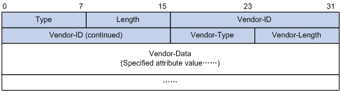
Protocols and Standards
The protocols and standards related to RADIUS include:
l RFC 2865: Remote Authentication Dial In User Service (RADIUS)
l RFC 2866: RADIUS Accounting
l RFC 2867: RADIUS Accounting Modifications for Tunnel Protocol Support
l RFC 2868: RADIUS Attributes for Tunnel Protocol Support
l RFC 2869: RADIUS Extensions
Configuring RADIUS
Configuration Task List
![]()
l The RADIUS scheme configured through the Web interface is named system.
l If there is no RADIUS scheme in the system, when you select Authentication > RADIUS to enter the RADIUS module, a scheme named system will be created automatically.
Table 4-3 lists the RADIUS configuration steps.
Table 4-3 RADIUS configuration task list
|
Task |
Description |
|
|
Configuring RADIUS Authentication Servers |
Required Configure the information related to the primary and secondary RADIUS authentication servers. By default, no RADIUS authentication server is configured. |
For configuration details, refer to Configuring RADIUS Servers. |
|
Configuring RADIUS Accounting Servers |
Optional Configure the information related to the primary and secondary RADIUS accounting servers. By default, no RADIUS accounting server is configured. |
|
|
Required Configure the parameters that are necessary for information exchange between the device and RADIUS servers. |
||
Configuring RADIUS Servers
From the navigation tree, select Authentication > RADIUS. The RADIUS server configuration page appears, as shown in Figure 4-5.
Figure 4-5 RADIUS server configuration
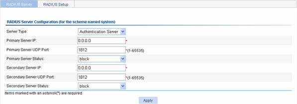
Table 4-4 lists the RADIUS server configuration items.
Table 4-4 RADIUS server configuration
|
Item |
Description |
|
Server Type |
Specify the type of the server to be configured, which can be Authentication Server and Accounting Sever. |
|
Primary Server IP |
Specify the IP address of the primary server. If no primary server is specified, the text box displays 0.0.0.0. To remove the previously configured primary server, enter 0.0.0.0 in the text box. The specified IP address of the primary server cannot be the same as that of the secondary server. |
|
Primary Server UDP Port |
Specify the UDP port of the primary server If the IP address of the primary server is not specified or the specified IP address is to be removed, the port number is 1812 for authentication or 1813 for accounting. |
|
Primary Server Status |
Set the status of the primary server, including: l active: The server is working normally. l blocked: The server is down. If the IP address of the primary server is not specified or the specified IP address is to be removed, the status is blocked. |
|
Secondary Server IP |
Specify the IP address of the secondary server. If no secondary server is specified, the text box displays 0.0.0.0. To remove the previously configured secondary server, enter 0.0.0.0 in the text box. The specified IP address of the secondary server cannot be the same as that of the primary server. |
|
Secondary Server UDP Port |
Specify the UDP port of the secondary server If the IP address of the secondary server is not specified or the specified IP address is to be removed, the port number is 1812 for authentication or 1813 for accounting. |
|
Secondary Server Status |
Status of the secondary server, including: l active: The server is working normally. l blocked: The server is down. If the IP address of the secondary server is not specified or the specified IP address is to be removed, the status is blocked. |
Return to RADIUS configuration task list.
Configuring RADIUS Parameters
From the navigation tree, select Authentication > RADIUS and then select the RADIUS Setup tab to enter the RADIUS parameter configuration page, as shown in Figure 4-6.
Figure 4-6 RADIUS parameter configuration
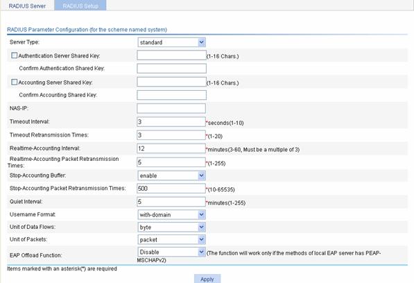
Table 4-5 lists the RADIUS parameters.
|
Item |
Description |
|
Server Type |
Specify the type of the RADIUS server supported by the device, including: l extended: Specifies an extended RADIUS server (CAMS server). That is, the RADIUS client (the device) and RADIUS server communicate using the proprietary RADIUS protocol and packet format. l standard: Specifies a standard RADIUS server. That is, the RADIUS client (the device) and RADIUS server communicate using the standard RADIUS protocol and packet format defined in RFC 2138/2139 or later. |
|
Authentication Server Shared Key |
Specify and confirm the shared key for the authentication server. These two parameters must have the same values. |
|
Confirm Authentication Shared Key |
|
|
Accounting Server Shared Key |
Specify and confirm the shared key for the accounting server. These two parameters must have the same values. |
|
Confirm Accounting Shared Key |
|
|
NAS-IP |
Specify the source IP address for the device to use in RADIUS packets to be sent to the RADIUS server. It is recommended to use a loopback interface address instead of a physical interface address as the source IP address, because if the physical interface is down, the response packets from the server cannot reach the device. |
|
Timeout Interval |
Set the RADIUS server response timeout. |
|
Timeout Retransmission Times |
Set the maximum number of transmission attempts. The product of the timeout value and the number of retransmission attempts cannot exceed 75. |
|
Realtime-Accounting Interval |
Set the real-time accounting interval, whose value must be n times 3 (n is an integer). To implement real-time accounting on users, it is necessary to set the real-time accounting interval. After this parameter is specified, the device will send the accounting information of online users to the RADIUS server every the specified interval. The value of the real-time accounting interval is related to the requirement on the performance of the NAS and RADIUS server. The smaller the value, the higher the requirement. It is recommended to set a large value if the number of users is equal to or larger than 1000. Table 4-6 shows the relationship between the interval value and the number of users. |
|
Realtime-Accounting Packet Retransmission Times |
Set the maximum number of real-time accounting request retransmission times. |
|
Stop-Accounting Buffer |
Enable or disable buffering stop-accounting requests without responses in the device. |
|
Stop-Accounting Packet Retransmission Times |
Set the maximum number of transmission attempts if no response is received for the stop-accounting packet. |
|
Quiet Interval |
Specify the interval the primary server has to wait before being active |
|
Username Format |
Set the format of username sent to the RADIUS server. A username is generally in the format of userid@isp-name, of which isp-name is used by the device to determine the ISP domain to which a user belongs. If a RADIUS server does not accept a username including an ISP domain name, you can configure the device to remove the domain name of a username before sending it to the RADIUS server. without-domain: Specifies to remove the domain name of a username that is to be sent to the RADIUS server. with-domain: Specifies to keep the domain name of a username that is to be sent to the RADIUS server. |
|
Unit of Data Flows |
Specify the unit for data flows sent to the RADIUS server, which can be: l byte l kilo-byte l mega-byte l giga-byte |
|
Unit of Packets |
Specify the unit for data packets sent to the RADIUS server, which can be l one-packet l kilo-packet l mega-packet l giga-packet |
Table 4-6 Relationship between the real-time accounting interval and the number of users
|
Number of users |
Real-time accounting interval (in minutes) |
|
1 to 99 |
3 |
|
100 to 499 |
6 |
|
500 to 999 |
12 |
|
¦1000 |
¦15 |
Return to RADIUS configuration task list.
RADIUS Configuration Example
Network requirements
As shown in Figure 4-7, it is required to configure the device to let the RADIUS server assign an IP address to the Telnet user and authenticate and keep accounts (online time statistics) on the user.
On the RADIUS server, the Telnet username, password, and the shared key expert have been configured.
On the device, it is required to configure the shared key as expert, and configure the system to remove the domain name of a username before sending it to the RADIUS server.
Figure 4-7 RADIUS server configuration
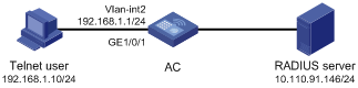
Configuration procedure
![]()
Enable the Telnet server function, and configure the AC to use AAA for Telnet user authentication. The configuration steps are omitted.
1) Configure IP addresses for the interfaces. (Omitted)
2) Configure RADIUS scheme system
# Configure the RADIUS authentication and accounting servers.
l From the navigation tree, select Authentication > RADIUS. The RADIUS server configuration page appears.
l Select Authentication Server as the server type.
l Enter 10.110.91.146 as the IP address of the primary authentication server
l Enter 1812 as the UDP port of the primary accounting server.
l Click Apply.
l Select Accounting Server as the server type.
l Enter 10.110.91.146 as the IP address of the primary accounting server.
l Enter 1813 as the UDP port of the primary accounting server.
l Click Apply.
# Configure the parameters for communication between the device and the RADIUS servers.
l Select the RADIUS Setup tab.
l Select the Authentication Server Shared Key check box and enter expert in the text box.
l Enter expert in the Confirm Authentication Shared Key text box.
l Select the Accounting Server Shared Key check box and enter expert in the text box.
l Enter expert in the Confirm Accounting Shared Key text box.
l Select without-domain for the username format.
l Click Apply
3) Configure AAA
# Create an ISP domain.
l From the navigation tree, select Authentication > AAA. The domain setup page appears.
l Enter test in the Domain Name textbox.
l Select Enable to use the domain as the default domain.
l Click Apply.
# Configure the authentication, authorization, and accounting schemes for the ISP domain.
l Select the Authentication tab.
l Select the domain name test.
l Select the Default AuthN checkbox and then select RADIUS as the authentication mode.
l Select system from the Name drop-down list to use it as the authentication scheme.
l Click Apply.
l Select the Authorization tab.
l Select the domain name test.
l Select the Default AuthZ checkbox and then select RADIUS as the authorization mode.
l Select system from the Name drop-down list to use it as the authorization scheme.
l Click Apply.
l Select the Accounting tab.
l Select the domain name test.
l Select the Default Accounting checkbox and then select RADIUS as the accounting mode.
l Select system from the Name drop-down list to use it as the accounting scheme.
l Click Apply.
RADIUS Configuration Guidelines
When configuring the RADIUS client, note that:
1) When you modify the parameters of the RADIUS scheme, the system does not check whether the scheme is being used by users.
2) After accounting starts, update-accounting and stop-accounting packets will be sent to the designated server, and no primary/secondary server switchover will take place even if the designated server fails. Such a switchover can take place only during AAA session establishment.
3) If an AAA server has active TCP connections, it cannot be removed.
4) RADIUS does not support accounting for FTP users.
5) If the H3C CAMS server is used as the RADIUS server, it is necessary to configure accounting as optional for users in the ISP domain because the CAMS server does not respond to accounting packets.
5 Local EAP Service Configuration
Local EAP Service Overview
In some simple application environments, you may want to use an access device to authenticate users locally, instead of deploying AAA servers for user authentication. In this case, if the Extensible Authentication Protocol (EAP) is used for user access authentication, you need to configure the local EAP authentication server to cooperate with local authentication method of AAA for local EAP authentication. For details about AAA, refer to AAA Configuration.
Configuring Local EAP Service
Select Authentication > Local EAP Server from the navigation. The Local EAP service configuration page appears, as shown in Figure 5-1.
Figure 5-1 Local EAP service configuration page
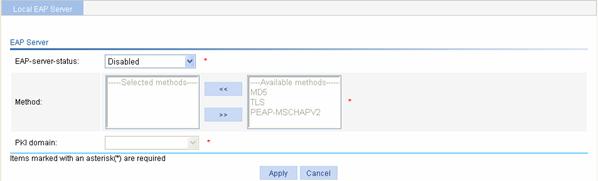
Table 5-1 describes the configuration items for configuring the local EAP service.
Table 5-1 Local EAP service configuration items
|
Item |
Description |
|
EAP-server-status |
Enable or disable the EAP server. When the EAP server is enabled, you can perform the following configurations. |
|
Method |
Specify the EAP authentication methods, including: l MD5: Uses Message Digest 5 (MD5) for authentication. l PEAP-MSCHAPV2: Uses Protected Extensible Authentication Protocol (PEAP) for authentication and, specially, uses the Microsoft Challenge Handshake Authentication Protocol version 2 (MSCHAPv2) for authentication in the established TLS tunnel. l TLS: Uses the Transport Layer Security (TLS) protocol for authentication. You can select more than one authentication method. An authentication method selected earlier has a higher priority. When an EAP client and the local server communicate for EAP authentication, they first negotiate the EAP authentication method to be used. During negotiation, the local server prefers the authentication method with the highest priority from the EAP authentication method list. If the client supports the authentication method, the negotiation succeeds and they proceed with the authentication process. Otherwise, the local server tries the one with the next highest priority until a supported one is found, or if none of the authentication methods are found supported, the local server sends an EAP-Failure packet to the client for notification of the authentication failure. |
|
PKI Domain |
Specify the PKI domain for EAP authentication. Available PKI domains are those configured on the page you enter by selecting Authentication > PKI. For details about PKI domain, refer to PKI Configuration.
l The service management, local portal authentication and local EAP service modules always reference the same PKI domain. Changing the referenced PKI domain in any of the three modules will also change that referenced in the other two modules. l All modules that need to use a PKI domain use the same PKI domain. To select a new PKI domain, you need to disable all these modules, enable them again, and then select a PKI domain for them. Otherwise, the new PKI domain does not take effect and the SSL module still uses the original PKI domain to retrieve certificates. |
Local EAP Service Configuration Example (for WX5002 Only)
Network requirements
As shown in Figure 5-2, configure AC to perform local EAP authentication and authorization for 802.1X users. The authentication method is EAP-TLS.
Figure 5-2 Network diagram for configuring local EAP service
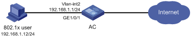
Configuration procedure
![]()
l To use the authentication method of EAP-TLS, configure the network properties of the connection and the client certificate properly on the client.
l Configure PKI domain test, and request a local certificate and the CA certificate. For details, refer to PKI Configuration.
1) Configure a local user.
# Create local user usera.
l Select Authentication > Users from the navigation tree. The Local User page appears. Click Add to enter the local user configuration page, as shown in Figure 5-3.
Figure 5-3 Local user configuration page
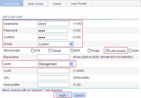
Perform the following configurations on the page:
l Type usera as the username.
l Type 1234 as the password.
l Type 1234 to confirm the password.
l Select LAN-Access as the service type.
l Select Management as the authorized level.
l Click Apply.
2) Configure the ISP domain.
# Configure the ISP domain system to use local authentication and local authorization (The ISP domain system uses local authentication and local authorization by default).
3) Configure the local EAP service.
# Enable the EAP server, configure the authentication method as TLS, and select PKI domain test.
l Select Authentication > Local EAP Server from the navigation tree to enter the local EAP configuration page, as shown in Figure 5-4.
Figure 5-4 Local EAP server configuration page
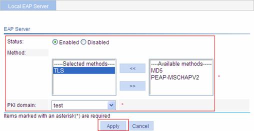
Perform the following configurations on the local EAP server configuration page:
l Select Enabled for the EAP server status.
l Select TLS from the Available methods list and click << to add TLS to the Selected methods list.
l Select PKI domain test.
l Click Apply.
4) Configure the AP.
# Create an AP.
l Select AP > AP Setup. Then click Add to enter the AP configuration page, as shown in Figure 5-5.
Figure 5-5 AP configuration page
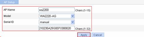
Perform the following configurations on the AP configuration page:
l Type wa2200 as the AP name.
l Select WA2220-AG as the device model.
l Select manual and type the serial number in the text box.
l Click Apply.
5) Configure the wireless service.
# Create the wireless service.
l Select Wireless Service > Access Service. Then, click Add to enter the page for adding a wireless service, as shown in Figure 5-6.
Figure 5-6 Create a wireless service
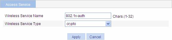
Perform the following configurations on this page:
l Type 802.1x-auth as the wireless service name.
l Select crypto as the service type.
l Click Apply.
The wireless service’s parameter configuration page appears, as shown in Figure 5-7.
Figure 5-7 Wireless service configuration page
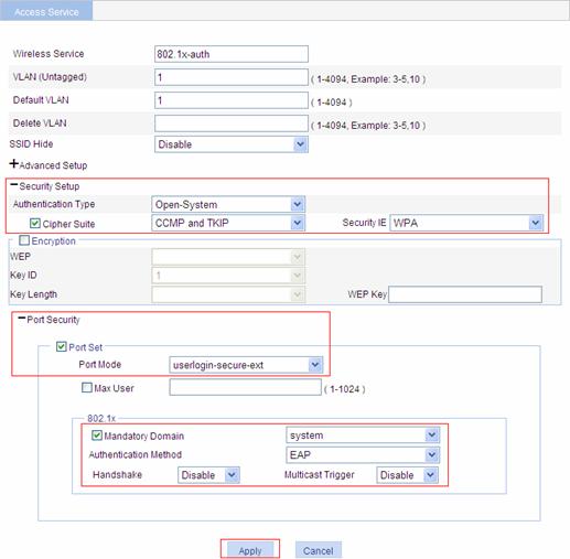
Perform the following configurations on this page:
l Click the expand button before Security Setup to expand the configuration items.
l Select Open-System as the authentication type.
l Select the Cipher Suite check box, and then select CCMP and TKIP (select a cipher suite according to your actual network requirements). Select WPA as the security IE.
l Click the expand button before Port Security to expand the configuration items.
l Select the Port Set check box.
l Select userlogin-secure-ext as the port mode.
l Select the Mandatory Domain check box, and then select system.
l Select EAP as the authentication method.
l Select Disable to disable the handshake function.
l Select Disable to disable the multicast trigger function.
l Click Apply. A configuration progress dialog box appears, as shown in Figure 5-8.
Figure 5-8 Configuration progress dialog box
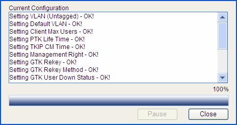
l After the configuration process is complete, click Close. When the configuration is in progress, a dialog box appears asking for your confirmation to enable the EAP service. Just confirm the operation to proceed.
# Enable the wireless service.
l After you complete the above configurations, the access service list page appears, as shown in Figure 5-9.
Figure 5-9 Enable the wireless service
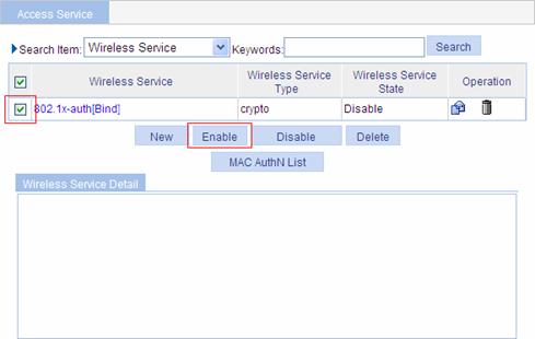
Perform the following configurations on this page:
l Select wireless service 802.1x-auth.
l Click Enable.
6) Bind the AP's radio mode with the wireless service.
l In the wireless service list shown in Figure 5-9, click the Bind link next to the wireless service name 802.1x-auth. The service-radio binding configuration page appears, as shown in Figure 5-10.
Figure 5-10 Bind the radio with the wireless service
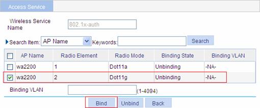
Perform the following configurations on this page:
l Select the AP of wa2200 with the radio mode being Dot11g.
l Click Bind.
7) Enable dot11g.
l Select Radio > Radio from the navigation tree to enter the radio configuration page, as shown in Figure 5-11.
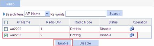
Perform the following configurations on this page:
l Select the AP of wa2200 with the radio mode being Dot11g.
l Click Enable.
8) Verify the configuration.
l After the above configurations, a client should be able to pass EAP authentication and access the wireless network.
l You can ping the client successfully from the AC.
User Overview
This module allows you to configure local users, user groups, guest users, and user profiles.
Local user
A local user represents a set of user attributes configured on a device (such as the user password, service type, and authorization attribute), and is uniquely identified by the username. For a user requesting a network service to pass local authentication, you must add an entry as required in the local user database of the device. For details about local authentication, refer to AAA Configuration.
User group
A user group consists of a group of local users and has a set of local user attributes. You can configure local user attributes for a user group to implement centralized management of user attributes for the local users in the group. All local users in a user group inherit the user attributes of the group, but if you configure user attributes for a local user, the settings of the local user take precedence over the settings for the user group.
By default, every newly added local user belongs to a user group named system, which is automatically created by the system.
Guest user
If some users need to access the network temperately, you can establish a guest user account for them and control access of the users as required.
User profile
A user profile is a configuration template for saving predefined configurations. You can configure different items for different user profiles to accommodate to different application scenarios, such as Quality of Service (QoS) policy, line rate, wireless service, and AP group.
When accessing the device, a user needs to be authenticated. During the authentication process, the authentication server sends the user profile name to the device, which then enables the configurations in the user profile. After the user passes the authentication and accesses the device, the device will restrict the user’s access based on the configurations in the user profile. When the user logs out, the device automatically disables the configurations in the user profile, removing the restrictions on the user as a result. As the mechanism indicates, user profiles are for restricting online users’ access. If no user is online (no user is accessing the network, no user has passed authentication, or all users have logged out), user profiles do not take effect.
With user profiles, you can:
l Restrict users’ access to the system resources more flexibly. For example, you can deploy traffic policing on a per-user basis by defining line rates in user profiles.
l Perform user access control more granularly. For example, you can control user access based on wireless access service, restricting users to access through only their specified SSIDs. With user profiles, you can also perform user access control based on AP, restricting users to use the APs in the specified AP groups to access the network resources.
Configuring Users
Configuring a Local User
Select Authentication > Users from the navigation tree. The Local User page appears, listing all local users and guest users, as shown in Figure 6-1. Click Add to enter the local user configuration page.
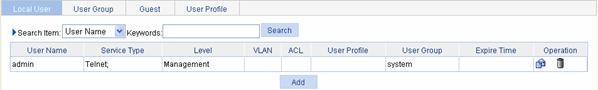
Table 6-1 describes the configuration items for creating a local user.
Table 6-1 Local user configuration items
|
Item |
Description |
|
|
Username |
Specify a name for the local user. The username cannot contain two or more consecutive spaces as well as the characters of ?, <, >, \, ”, %, ’, &, and #. |
|
|
Password |
Specify a password for the local user. |
|
|
Confirm |
Type the password again to confirm the password. |
|
|
Group |
Select a user group for the local user. For information about user group configuration, refer for Configuring a User Group. |
|
|
Service-type |
Select the service types for the local user to use, including FTP, Telnet, PPP, Portal, LAN access (accessing through the Ethernet, such as 802.1X users), and SSH.
If you do not specify any service type for a local user who uses local authentication, the user cannot pass authentication and therefore cannot log in. |
|
|
Expire-time |
Specify an expiration time for the local user, in the format HH:MM:SS-YYYY/MM/DD. When authenticating a local user with the expiration time argument configured, the access device checks whether the expiration time has elapsed. If not, the device permits the user to log in. |
|
|
Level |
Select an authorization level for the local user, which can be Visitor, Monitor, Configure, or Management, in ascending order of priority. |
Every authorization attribute has its definite application environments and purposes. Therefore, when configuring authorization attributes for a local user, determine what attributes are needed first. |
|
VLAN |
Specify the VLAN to be authorized to the local user after the user passes authentication. |
|
|
ACL |
Specify the ACL to be used by the access device to restrict the access of the local user after the user passes authentication. |
|
|
User-profile |
Specify the user profile for the local user. Only enabled user profiles are available in this field. For information about user profile configuration, refer to Configuring a User Profile. |
|
|
Password |
Specify and confirm the password of the local user. The settings of these two fields must be the same. |
|
|
Confirm |
||
Configuring a User Group
Select Authentication > Users from the navigation tree, and then select the User Group tab to display the existing user groups, as shown in Figure 6-2. Then, click Add to enter the user group configuration page.
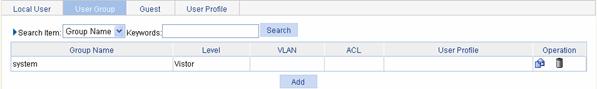
Table 6-2 describes the configuration items for creating a user group.
Table 6-2 User group configuration items
|
Item |
Description |
|
Group-name |
Specify a name for the user group. The group name cannot contain two or more consecutive spaces as well as the characters of ?, <, >, \, ”, %, ’, &, and #. |
|
Level |
Select an authorization level for the user group, which can be Visitor, Monitor, Configure, or Management, in ascending order of priority. |
|
VLAN |
Specify the VLAN to be authorized to users of the user group after the users pass authentication. |
|
ACL |
Specify the ACL to be used by the access device to restrict the access of the users of the user group after the users pass authentication. |
|
User-profile |
Specify the user profile for the user group. Only enabled user profiles are available in this field. For information about user profile configuration, refer to Configuring a User Profile. |
Configuring a Guest User
Select Authentication > Users from the navigation tree, and then select the Guest tab to display the guest user information, as shown in Figure 6-3. Then, click Add to enter the guest user configuration page.
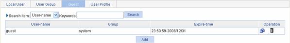
Table 6-3 describes the configuration items for creating a guest user.
Table 6-3 Guest user configuration items
|
Item |
Description |
|
Username |
Specify a name for the guest user. The username cannot contain two or more consecutive spaces as well as the characters of ?, <, >, \, ”, %, ’, &, and #. |
|
Password |
Specify a password for the guest user. |
|
Group |
Select a user group for the guest user. For information about user group configuration, refer to Configuring a User Group. |
|
Expire-time |
Specify an expiration time for the guest user, in the format HH:MM:SS-YYYY/MM/DD. When authenticating a local user with the expiration time argument configured, the access device checks whether the expiration time has elapsed. If not, the device permits the user to log in. |
|
Password |
Specify a password for the guest user. |
![]()
Guest users are
also displayed in the local user list. By clicking the ![]() icon of a guest user, you
can modify the settings of the guest user and configure authorization
attributes for the guest user.
icon of a guest user, you
can modify the settings of the guest user and configure authorization
attributes for the guest user.
Configuring a User Profile
Select Authentication > Users from the navigation tree, and then select the User Profile tab to display the existing user profiles, as shown in Figure 6-4. Then, click Add to enter the user profile configuration page.
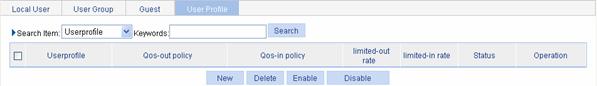
Table 6-4 describes the configuration items for creating a user profile.
Table 6-4 User profile configuration items
|
Item |
Description |
|
Userprofile name |
Specify a name for the user profile. |
After the above configuration, click Apply to submit your configuration and enter the details configuration page.
Table 6-5 describes the user profile details configuration items.
Table 6-5 User profile details configuration items
|
Item |
Description |
|
Userprofile name |
This field displays the name of the user profile. |
|
Qos-out policy |
Specify whether the device applies the QoS policy in the outbound direction for online users who use the user profile. |
|
Qos-in policy |
Specify whether the device applies the QoS policy in the inbound direction for online users who use the user profile. |
|
limited-out rate |
Specify the rate limits in the outbound direction for online users who use the user profile. |
|
limited-in rate |
Specify the rate limits in the inbound direction for online users who use the user profile. |
|
Services permitted |
Specify the wireless services for the user profile. Select wireless services from the Services list and then click < to add them to the Selected services list. Available wireless services are those configured on the page you can enter by selecting Wireless Service > Access Service from the navigation tree. For details, refer to WLAN Service Configuration in Wireless Service. |
|
APs permitted |
Specify the AP groups for the user profile. Select AP groups form the APs list and then click < to add them to the Selected APs list. Available AP groups are those configured on the page you can enter by selecting AP > AP Group Management from the navigation tree. For details, refer to AP Group Management in AP. |
By default, a newly added user profile is disabled. You need to manually enable it by following these steps:
1) From the page displaying the existing user profiles, select the check box before the user profile to be enabled.
2) Click Enable.
![]()
l A user profile takes effect and the authentication server notifies users of authentication results only after the user profile is enabled. Therefore, if you do not enable the user profile, users using the user profile will not be able to get online.
l Only enabled user profiles can be referenced by users. Disabling a user profile will log out all users using the user profile.
l Enabled user profiles cannot be modified or removed. To modify or remove an enabled user profile, you need to disable it first.
PKI Overview
The Public Key Infrastructure (PKI) is a hierarchical framework designed for providing information security through public key technologies and digital certificates and verifying the identities of the digital certificate owners.
PKI employs digital certificates, which are bindings of certificate owner identity information and public keys. It allows users to obtain certificates, use certificates, and revoke certificates. By leveraging digital certificates and relevant services like certificate distribution and blacklist publication, PKI supports authenticating the entities involved in communication, and thus guaranteeing the confidentiality, integrity and non-repudiation of data.
PKI Terms
Digital certificate
A digital certificate is a file signed by a certificate authority (CA) that contains a public key and the related user identity information. A simplest digital certificate contains a public key, an entity name, and a digital signature from the CA. Generally, a digital certificate also includes the validity period of the key, the name of the CA and the sequence number of the certificate. A digital certificate must comply with the international standard of ITU-T X.509. This manual involves two types of certificates: local certificate and CA certificate. A local certificate is a digital certificate signed by a CA for an entity, while a CA certificate, also known as a root certificate, is signed by the CA for itself.
CRL
An existing certificate may need to be revoked when, for example, the user name changes, the private key leaks, or the user stops the business. Revoking a certificate is to remove the binding of the public key with the user identity information. In PKI, the revocation is made through certificate revocation lists (CRLs). Whenever a certificate is revoked, the CA publishes one or more CRLs to show all certificates that have been revoked. The CRLs contain the serial numbers of all revoked certificates and provide an effective way for checking the validity of certificates.
A CA may publish multiple CRLs when the number of revoked certificates is so large that publishing them in a single CRL may degrade network performance.
CA policy
A CA policy is a set of criteria that a CA follows in processing certificate requests, issuing and revoking certificates, and publishing CRLs. Usually, a CA advertises its policy in the form of certification practice statement (CPS). A CA policy can be acquired through out-of-band means such as phone, disk, and e-mail. As different CAs may use different methods to check the binding of a public key with an entity, make sure that you understand the CA policy before selecting a trusted CA for certificate request.
Architecture of PKI
A PKI system consists of entities, a CA, a registration authority (RA) and a PKI repository, as shown in Figure 7-1.
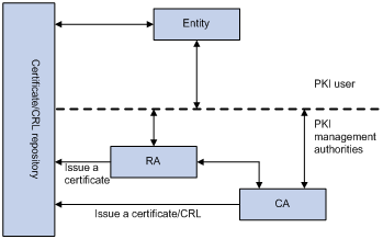
Entity
An entity is an end user of PKI products or services, such as a person, an organization, a device like a router or a switch, or a process running on a computer.
CA
A certificate authority (CA) is a trusted authority responsible for issuing and managing digital certificates. A CA issues certificates, specifies the validity periods of certificates, and revokes certificates as needed by publishing CRLs.
RA
A registration authority (RA) is an extended part of a CA or an independent authority. An RA can implement functions including identity authentication, CRL management, key pair generation and key pair backup. It only examines the qualifications of users; it does not sign certificates. Sometimes, a CA assumes the registration management responsibility and therefore there is no independent RA. The PKI standard recommends that an independent RA be used for registration management to achieve higher security of application systems.
PKI repository
A PKI repository can be a Lightweight Directory Access Protocol (LDAP) server or a common database. It stores and manages information like certificate requests, certificates, keys, CRLs and logs while providing a simple query function.
LDAP is a protocol for accessing and managing PKI information. An LDAP server stores user information and digital certificates from the RA server and provides directory navigation service. From an LDAP server, an entity can retrieve digital certificates of its own and other entities.
Applications of PKI
The PKI technology can satisfy the security requirements of online transactions. As an infrastructure, PKI has a wide range of applications. Here are some application examples.
VPN
A virtual private network (VPN) is a private data communication network built on the public communication infrastructure. A VPN can leverage network layer security protocols (for instance, IPSec) in conjunction with PKI-based encryption and digital signature technologies to achieve confidentiality.
Secure E-mail
E-mails require confidentiality, integrity, authentication, and non-repudiation. PKI can address these needs. The secure E-mail protocol that is currently developing rapidly is Secure/Multipurpose Internet Mail Extensions (S/MIME), which is based on PKI and allows for transfer of encrypted mails with signature.
Web security
For Web security, two peers can establish a Secure Sockets Layer (SSL) connection first for transparent and secure communications at the application layer. With PKI, SSL enables encrypted communications between a browser and a server. Both the communication parties can verify the identity of each other through digital certificates.
Operation of PKI
In a PKI-enabled network, an entity can request a local certificate from the CA and the device can check the validity of certificate. The following describes how it works:
1) An entity submits a certificate request to the CA.
2) The RA verifies the identity of the entity and then sends the identity information and the public key with a digital signature to the CA.
3) The CA verifies the digital signature, approves the application, and issues a certificate.
4) The RA receives the certificate from the CA, sends it to the LDAP server to provide directory navigation service, and notifies the entity that the certificate is successfully issued.
5) The entity retrieves the certificate. With the certificate, the entity can communicate with other entities safely through encryption and digital signature.
6) The entity makes a request to the CA when it needs to revoke its certificate, while the CA approves the request, updates the CRLs and publishes the CRLs on the LDAP server.
Configuring PKI
Configuration Task List
There are two PKI certificate request modes:
l Manual: In manual mode, you need to retrieve a CA certificate, generate a local RSA key pair, and submit a local certificate request for an entity.
l Auto: In auto mode, an entity automatically requests a certificate through the Simple Certification Enrollment Protocol (SCEP) when it has no local certificate or the present certificate is about to expire.
You can specify the PKI certificate request mode for a PKI domain. Different PKI certificate request modes require different configurations:
Requesting a certificate manually
Perform the tasks in Table 7-1 to request a certificate manually.
Table 7-1 Configuration task list for requesting a certificate manually
|
Task |
Remarks |
|
Required Create a PKI entity and configure the identity information. A certificate is the binding of a public key and an entity, where an entity is the collection of the identity information of a user. A CA identifies a certificate applicant by entity. The identity settings of an entity must be compliant to the CA certificate issue policy. Otherwise, the certificate request may be rejected. |
|
|
Required Create a PKI domain, setting the certificate request mode to Manual. Before requesting a PKI certificate, an entity needs to be configured with some enrollment information, which is referred to as a PKI domain. A PKI domain is intended only for convenience of reference by other applications like IKE and SSL, and has only local significance. |
|
|
Required Generate a local RSA key pair. By default, no local RSA key pair exists. Generating an RSA key pair is an important step in certificate request. The key pair includes a public key and a private key. The private key is kept by the user, while the public key is transferred to the CA along with some other information.
If there is already a local certificate, you need to remove the certificate before generating a new key pair, so as to keep the consistency between the key pair and the local certificate. |
|
|
Retrieving the CA certificate |
Required Certificate retrieval serves two purposes: l Locally store the certificates associated with the local security domain for improved query efficiency and reduced query count, l Prepare for certificate verification.
If there are already CA certificates locally, you cannot perform the CA certificate retrieval operation. This is to avoid possible mismatch between certificates and registration information resulting from relevant changes. To retrieve the CA certificate, you need to remove the CA certificate and local certificate first. |
|
Required When requesting a certificate, an entity introduces itself to the CA by providing its identity information and public key, which will be the major components of the certificate. A certificate request can be submitted to a CA in two ways: online and offline. l In online mode, if the request is granted, the local certificate will be retrieved to the local system automatically. l In offline mode, you need to retrieve the local certificate by an out-of-band means.
If there is already a local certificate, you cannot perform the local certificate retrieval operation. This is to avoid possible mismatch between the local certificate and registration information resulting from relevant changes. To retrieve a new local certificate, you need to remove the CA certificate and local certificate first. |
|
|
Optional Destroy the existing RSA key pair and the corresponding local certificate. If the certificate to be retrieved contains an RSA key pair, you need to destroy the existing key pair. Otherwise, the retrieving operation will fail. |
|
|
Optional Retrieve an existing certificate. |
|
|
Optional Retrieve a CRL and display its contents. |
Requesting a Certificate Automatically
Perform the tasks in Table 7-2 to configure the PKI system to request a certificate automatically.
Table 7-2 Configuration task list for requesting a certificate automatically
|
Task |
Remarks |
|
Required Create a PKI entity and configure the identity information. A certificate is the binding of a public key and an entity, where an entity is the collection of the identity information of a user. A CA identifies a certificate applicant by entity. The identity settings of an entity must be compliant to the CA certificate issue policy. Otherwise, the certificate request may be rejected. |
|
|
Required Create a PKI domain, setting the certificate request mode to Auto. Before requesting a PKI certificate, an entity needs to be configured with some enrollment information, which is referred to as a PKI domain. A PKI domain is intended only for convenience of reference by other applications like IKE and SSL, and has only local significance. |
|
|
Optional Destroy the existing RSA key pair and the corresponding local certificate. If the certificate to be retrieved contains an RSA key pair, you need to destroy the existing key pair. Otherwise, the retrieving operation will fail. |
|
|
Optional Retrieve an existing certificate. |
|
|
Optional Retrieve a CRL and display its contents. |
Creating a PKI Entity
Select Authentication > PKI from the navigation tree. The PKI entity list page is displayed by default, as shown in Figure 7-2. Click Add on the page to enter the PKI entity configuration page.
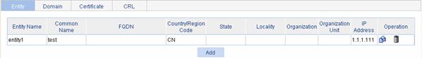
Table 7-3 describes the configuration items for creating a PKI entity.
Table 7-3 PKI entity configuration items
|
Item |
Description |
|
Entity Name |
Type the name for the PKI entity. |
|
Common Name |
Type the common name for the entity. |
|
IP Address |
Type the IP address of the entity. |
|
FQDN |
Type the fully qualified domain name (FQDN) for the entity. An FQDN is a unique identifier of an entity on the network. It consists of a host name and a domain name and can be resolved to an IP address. For example, www.whatever.com is an FQDN, where www indicates the host name and whatever.com the domain name. |
|
Country/Region Code |
Type the country or region code for the entity. |
|
State |
Type the state or province for the entity. |
|
Locality |
Type the locality for the entity. |
|
Organization |
Type the organization name for the entity. |
|
Organization Unit |
Type the unit name for the entity. |
Return to Configuration task list for requesting a certificate manually.
Return to Configuration task list for requesting a certificate automatically.
Creating a PKI Domain
Select Authentication > PKI from the navigation tree, and then select the Domain tab to enter the page displaying existing PKI domains, as shown in Figure 7-3. Then, click Add to enter the PKI domain configuration page.
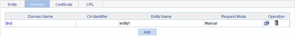
Table 7-4 describes the configuration items for creating a PKI domain.
Table 7-4 PKI domain configuration items
|
Item |
Description |
|
Domain Name |
Type the name for the PKI domain. |
|
CA Identifier |
Type the identifier of the trusted CA. An entity requests a certificate from a trusted CA. The trusted CA takes the responsibility of certificate registration, distribution, and revocation, and query. In offline mode, this item is optional; while in other modes, this item is required. |
|
Entity Name |
Select the local PKI entity. When submitting a certificate request to a CA, an entity needs to show its identity information. Available PKI entities are those that have been configured. |
|
Institution |
Select the authority for certificate request. l CA: Indicates that the entity requests a certificate from a CA. l RA: Indicates that the entity requests a certificate from an RA. RA is recommended. |
|
Requesting URL |
Type the URL of the RA. The entity will submit the certificate request to the server at this URL through the SCEP protocol. The SCEP protocol is intended for communication between an entity and an authentication authority. In offline mode, this item is optional; while in other modes, this item is required.
Currently, this item does not support domain name resolution. |
|
LDAP IP |
Type the IP address, port number and version of the LDAP server. In a PKI system, the storage of certificates and CRLs is a crucial problem, which is usually addressed by deploying an LDAP server. |
|
Port |
|
|
Version |
|
|
Request Mode |
Select the online certificate request mode, which can be auto or manual. |
|
Password Encrypt |
Select this check box to display the password in cipher text. This check box is available only when the certificate request mode is set to Auto. |
|
Password |
Type the password for certificate revocation. This item is available only when the certificate request mode is set to Auto. |
|
Hash |
Specify the hash algorithm and fingerprint for verification of the CA root certificate. Upon receiving the root certificate of the CA, an entity needs to verify the fingerprint of the root certificate, namely, the hash value of the root certificate content. This hash value is unique to every certificate. If the fingerprint of the root certificate does not match the one configured for the PKI domain, the entity will reject the root certificate.
The fingerprint of the CA root certificate is required when the certificate request mode is Auto, and can be omitted when the certificate request mode is Manual. When it is omitted, no CA root certificate verification occurs automatically and you need to verify the CA server by yourself. |
|
Fingerprint |
|
|
Polling Count |
Set the polling interval and attempt limit for querying the certificate request status. After an entity makes a certificate request, the CA may need a long period of time if it verifies the certificate request in manual mode. During this period, the applicant needs to query the status of the request periodically to get the certificate as soon as possible after the certificate is signed. |
|
Polling Interval |
|
|
Enable CRL Checking |
Select this box to specify that CRL checking is required during certificate verification. |
|
CRL Update Period |
Type the CRL update period, that is, the interval at which the PKI entity downloads the latest CRLs. This item is available when the Enable CRL Checking check box is selected. By default, the CRL update period depends on the next update field in the CRL file. |
|
CRL URL |
Type the URL of the CRL distribution point. This item is available when the Enable CRL Checking check box is selected. Note that when the URL of the CRL distribution point is not set, you should acquire the CA certificate and a local certificate, and then acquire a CRL through SCEP.
Currently, this item does not support domain name resolution. |
Return to Configuration task list for requesting a certificate manually.
Return to Configuration task list for requesting a certificate automatically.
Generating an RSA Key Pair
Select Authentication > PKI from the navigation tree, and then select the Certificate tab to enter the page displaying existing PKI certificates, as shown in Figure 7-4. Then, click Create Key to enter RSA key pair configuration page.
Figure 7-4 Certificate configuration page
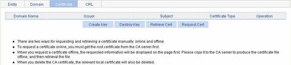
Table 7-5 describes the configuration items for generating an RSA key pair.
Table 7-5 Configuration items for generating an RSA key pair
|
Item |
Description |
|
Key Length |
Type the length of the RSA keys. |
Return to Configuration task list for requesting a certificate manually.
Destroying the RSA Key Pair
Select Authentication > PKI from the navigation tree, and then select the Certificate tab to enter the page displaying existing PKI certificates, as shown in Figure 7-4. Click Destroy Key to enter RSA key pair destruction page. Then, click Apply to destroy the existing RSA key pair and the corresponding local certificate.
Return to Configuration task list for requesting a certificate manually.
Return to Configuration task list for requesting a certificate automatically.
Retrieving a Certificate
You can download an existing CA certificate or local certificate from the CA server and save it locally. To do so, you can use two ways: online and offline. In offline mode, you need to retrieve a certificate by an out-of-band means like FTP, disk, e-mail and then import it into the local PKI system.
Select Authentication > PKI from the navigation tree, and then select the Certificate tab to enter the page displaying existing PKI certificates, as shown in Figure 7-4. Click Retrieve Cert to enter PKI certificate retrieval page.
Table 7-6 describes the configuration items for retrieving a PKI certificate.
Table 7-6 Configuration items for retrieving a PKI certificate
|
Item |
Description |
|
Domain Name |
Select the PKI domain for the certificate. |
|
Certificate Type |
Select the type of the certificate to be retrieved, which can be CA or local. |
|
Enable Offline Mode |
Select this check box to retrieve a certificate in offline mode (that is, by an out-of-band means like FTP, disk, or e-mail) and then import the certificate into the local PKI system. |
|
File Format |
Specify the file format and the file name. This item is available when the Enable Offline Mode check box is selected. |
|
Filename |
|
|
Password |
Enter the password that is specified when the certificate is exported for protecting the private key. |
After retrieving a certificate, you can click View Cert corresponding to the certificate from the PKI certificates list to display the contents of the certificate.
Return to Configuration task list for requesting a certificate manually.
Return to Configuration task list for requesting a certificate automatically.
Requesting a Local Certificate
Select Authentication > PKI from the navigation tree, and then select the Certificate tab to enter the page displaying existing PKI certificates, as shown in Figure 7-4. Click Request Cert to enter the local certificate request page.
Table 7-7 describes the configuration items for requesting a local certificate.
Table 7-7 Configuration items for requesting a local certificate
|
Item |
Description |
|
Domain Name |
Select the PKI domain for the certificate. |
|
Password |
Type the password for certificate revocation. |
|
Enable Offline Mode |
Select this check box to request a certificate in offline mode, that is, by an out-of-band means like FTP, disk, or e-mail. |
If you select the offline mode and click Apply, the offline certificate request information page appears. Submit the information to the CA to request a local certificate.
Return to Configuration task list for requesting a certificate manually.
Retrieving and Displaying a CRL
Select Authentication > PKI from the navigation tree, and then select the CRL tab to enter the page displaying CRLs, as shown in Figure 7-5.
Figure 7-5 CRL page

l Click Retrieve CRL to retrieve the CRL of a domain.
l Then, click View CRL for the domain to display the contents of the CRL.
Return to Configuration task list for requesting a certificate manually.
Return to Configuration task list for requesting a certificate automatically.
PKI Configuration Example
Configuring a PKI Entity to Request a Certificate from a CA
Network requirements
Configure the access controller (AC) working as the PKI entity, so that:
l The AC submits a local certificate request to the CA server, which runs the RSA Keon software.
l The AC acquires CRLs for certificate verification.
Figure 7-6 Diagram for configuring a PKI entity to request a certificate from a CA
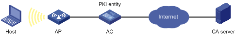
Configuration procedure
1) Configure the CA server
# Create a CA server named myca.
In this example, you need to configure the basic attributes of Nickname and Subject DN on the CA server at first:
l Nickname: Name of the trusted CA.
l Subject DN: DN information of the CA, including the Common Name (CN),
l Organization Unit (OU),
l Organization (O), and
l Country (C).
The other attributes may use the default values.
# Configure extended attributes
After configuring the basic attributes, you need to perform configuration on the Jurisdiction Configuration page of the CA server. This includes selecting the proper extension profiles, enabling the SCEP autovetting function, and adding the IP address list for SCEP autovetting.
# Configure the CRL publishing behavior
After completing the above configuration, you need to perform CRL related configurations.
In this example, select the local CRL publishing mode of HTTP and set the HTTP URL to http://4.4.4.133:447/myca.crl.
After the above configuration, make sure that the system clock of the device is synchronous to that of the CA, so that the device can request certificates and retrieve CRLs properly.
2) Configure AC
# Create a PKI entity.
l Select Authentication > PKI from the navigation tree. The PKI entity list page is displayed by default. Click Add on the page.
l Type aaa as the PKI entity name.
l Type ac as the common name.
l Click Apply.
# Create a PKI domain.
l Select the Domain tab, and then click Add.
l Type torsa as the PKI domain name.
l Type myca as the CA identifier.
l Select aaa as the local entity.
l Select CA as the authority for certificate request.
l Type http://4.4.4.133:446/c95e970f632d27be5e8cbf80e971d9c4a9a93337 as the URL for certificate request. The URL must be in the format of http://host:port/Issuing Jurisdiction ID, where Issuing Jurisdiction ID is the hexadecimal string generated on the CA.
l Select Manual as the certificate request mode.
l Click Display Advanced Config to display the advanced configuration items.
l Select the Enable CRL Checking check box.
l Type http://4.4.4.133:447/myca.crl as the CRL URL.
l Click Apply.
# Generate an RSA key pair.
l Select the Certificate tab, and then click Create Key.
l Click Apply to generate an RSA key pair.
# Retrieve the CA certificate.
l Select the Certificate tab, and then click Retrieve Cert.
l Select torsa as the PKI domain.
l Select CA as the certificate type.
l Click Apply.
# Request a local certificate.
l Select the Certificate tab, and then click Request Cert.
l Select torsa as the PKI domain.
l Select Password and then type challenge-word as the password.
l Click Apply.
# Retrieve the CRL.
l After retrieving a local certificate, select the CRL tab.
l Click Retrieve CRL of the PKI domain of torsa.
PKI Configuration Guidelines
When configuring PKI, note that:
1) Make sure the clocks of entities and the CA are synchronous. Otherwise, the validity period of certificates will be abnormal.
2) The Windows 2000 CA server has some restrictions on the data length of a certificate request. If the PKI entity identity information in a certificate request goes beyond a certain limit, the server will not respond to the certificate request.
3) The SCEP plug-in is required when you use the Windows Server as the CA. In this case, you need to specify RA as the authority for certificate request when configuring the PKI domain.
4) The SCEP plug-in is not required when you use the RSA Keon software as the CA. In this case, you need to specify CA as the authority for certificate request when configuring the PKI domain.