- Table of Contents
-
- H3C WX Series Access Controllers Web-Based Configuration Manual-6PW103
- 00-1Cover
- 01-Quick Start
- 02-Web Overview
- 03-Summary
- 04-Device
- 05-Network
- 06-AP Configuration
- 07-WLAN Service Configuration
- 08-WLAN Roaming Configuration
- 09-Radio Configuration
- 10-Authentication
- 11-Security
- 12-QoS
- 13-SNMP
- 14-Advanced Settings
- Related Documents
-
| Title | Size | Download |
|---|---|---|
| 04-Device | 337.11 KB |
2 Device Basic Information Configuration
Configuring Device Basic Information
Configuring Idle Timeout Period
Setting Syslog Related Parameters
Configuring Interface Management
Displaying Interface Information and Statistics
Shutting Down/Bringing Up an Interface
10 Port Mirroring Configuration
Introduction to Port Mirroring
Configuring Ports for a Mirroring Group
Switching the User Access Level to the Management Level
l The sample Web page information in this manual was created on the WX5002. The Web page information on your device may vary.
l The models listed in this manual are not applicable to all regions. Please consult the local agents for the models applicable to your region.
The following table shows the support of the H3C WX series access controller products for features:
|
Feature |
WX5000 series |
WX6000 series |
WX3000 series |
||||||
|
WX5002 |
LS8M1WCMA0 |
WX5004 |
WX6103 |
LSQM1WCMB0 |
LSBM1WCM2A0 |
WX3024 |
WX3010 |
WX3008 |
|
|
Loopback test |
Only GE interfaces support this feature. |
Only GE interfaces support internal loopback test. |
Only GE interfaces support this feature. |
Only XGE interfaces support internal loopback test. |
Only XGE interfaces support internal loopback test. |
Only XGE interfaces support internal loopback test. |
Only GE interfaces support internal loopback test. |
Only GE interfaces support internal loopback test. |
Only GE interfaces support internal loopback test. |
|
Port Mirroring |
Supported |
Not supported |
Supported |
Not supported |
Not supported |
Not supported |
Not supported |
Not supported |
Not supported |
Overview
Licenses are used on the H3C WX series access controller products to control how many APs can be connected concurrently to a WX access controller product. The supported number of concurrent APs depends on the device model.
![]()
l The WX5002-64 supports 32 concurrent APs by default, and can be extended to support 64.
l The WX5002-128 does not support the license function.
l The WX5004 supports 64 concurrent APs by default, and can be extended to support 256.
l The WX6000 series support 128 concurrent APs by default, and can be extended to support 640.
l The WX3024 unified switch supports 24 concurrent APs by default, and can be extended to support 48.
l The WX3010 and WX3008 unified switches support 12 concurrent APs by default, and can be extended to support 24.
Configuring License
![]()
After adding the license successfully, you need to reboot the device to make the license effective.
Select Device > License from the navigation tree to enter the license configuration page, as shown in Figure 1-1.
Figure 1-1 License configuration
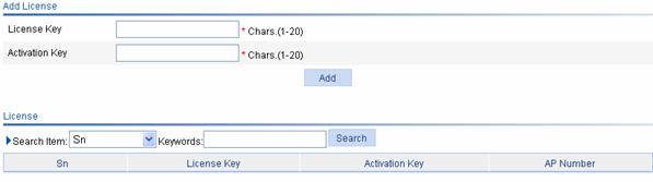
Table 1-1 describes license configuration items.
Table 1-1 License configuration items
|
Item |
Description |
|
License Key |
Type the license key of the license. |
|
Activation Key |
Type the activation key of the license. |
Check that Activation Key you input is correct and click Add. The license is displayed in the license table.
Overview
The device basic information feature provides you the following functions:
l Set the system name of the device
l Set the idle timeout period for a logged-in user. That is, the system will log an idle user off the Web for security purpose after the configured period.
Configuring Device Basic Information
Configuring System Name
Select Device > Basic from the navigation tree to enter the system name page, as shown in Figure 2-1.

Table 2-1 describes the system name configuration item.
Table 2-1 System name configuration item
|
Item |
Description |
|
Sysname |
Set the system name, which cannot include question marks (?), less than signs (<), greater than signs (>), backward slashes (\), double quotation marks (“), percent signs (%), single quotation marks (‘), ampersand signs (&) or pound signs (#). |
Configuring Idle Timeout Period
Select Device > Basic from the navigation tree to enter the idle timeout page, as shown in Figure 2-2.
Figure 2-2 Configuring idle timeout period
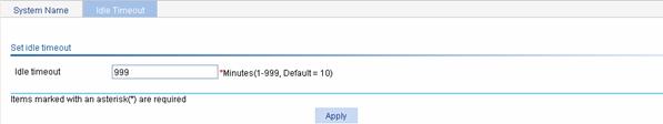
Table 2-2 describes the idle timeout period configuration item.
Table 2-2 Idle timeout period configuration item
|
Item |
Description |
|
Idle timeout |
Set the idle timeout period for a logged-in user |
Overview
You need to configure a correct system time so that the device can work with other devices properly.
The device supports setting system time through manual configuration and automatic synchronization of NTP server time.
An administrator can by no means keep time synchronized among all the devices within a network by changing the system clock on each device, because this is a huge amount of workload and cannot guarantee the clock precision. NTP, however, allows quick clock synchronization within the entire network and ensures a high clock precision.
Defined in RFC 1305, the Network Time Protocol (NTP) synchronizes timekeeping among distributed time servers and clients. NTP runs over the User Datagram Protocol (UDP), using UDP port 123.
The purpose of using NTP is to keep consistent timekeeping among all clock-dependent devices within the network so that the devices can provide diverse applications based on the consistent time.
System Time
Select Device > System Time from the navigation tree to enter the system time configuration page, as shown in Figure 3-1. On the upper side of the interface, the current system time is displayed.
Figure 3-1 System time configuration page
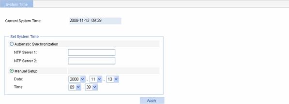
Table 3-1 describes the configuration items.
Table 3-1 System time configuration items
|
Item |
Description |
|
|
Automatic Synchronization |
NTP Server 1 |
Enable clock automatic synchronization with an NTP server. You can specify two NTP servers by inputting their IP addresses. NTP Server 1 is the primary and NTP Server 2 is the secondary.
l With automatic synchronization configured, the device periodically synchronizes its time with the NTP server. If the synchronization fails, the system uses the manually configured time; after the synchronization recovers, the system uses the synchronized time. l The IP address of an NTP server is a host address, and cannot be a broadcast or a multicast address, or the IP address of the local clock. |
|
NTP Server 2 |
||
|
Manual Setup |
Date |
Set the system time manually. The date and time is in the form of Year/Month/Day and Hour:Minute. |
|
Time |
||
Overview
System logs contain a large amount of network and device information, including running status and configuration changes. System logs are an important way for administrators to know network and device status. With system log information, administrators can take corresponding actions against network problems and security problems.
System logs can be stored in the log buffer, or sent to the loghost.
Configuring System Logs
Configuration Task List
Perform the tasks in Table 4-1 to configure system logs.
Table 4-1 System logs configuration task list
|
Task |
Description |
|
Optional Set the number of logs that can be stored in the log buffer. Set the refresh period of the log information displayed on the Web interface. |
|
|
Display detailed information of system logs. |
|
|
Optional Set the loghost that can receive system logs. |
Setting Syslog Related Parameters
Select Device > Syslog from the navigation tree, and click the Logset tab to enter the syslog configuration page, as shown in Figure 4-1.
Figure 4-1 Set system logs related parameters
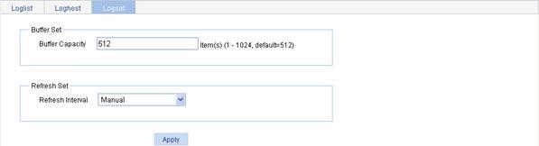
Table 4-2 describes the syslog configuration items.
Table 4-2 Syslog configuration items
|
Item |
Description |
|
Log Buffer Size |
Sets the number of logs that can be stored in the log buffer. |
|
Refresh Period |
Sets the refresh period on the log information displayed on the Web interface. You can select manual refresh or automatic refresh: l Manual: You need to click Refresh to refresh the Web interface when displaying log information. l Automatic: You can select to refresh the Web interface every 1 minute, 5 minutes, or 10 minutes. |
Return to System logs configuration task list.
Displaying Syslog
Select Device > Syslog from the navigation tree to enter the syslog display page, as shown in Figure 4-2.
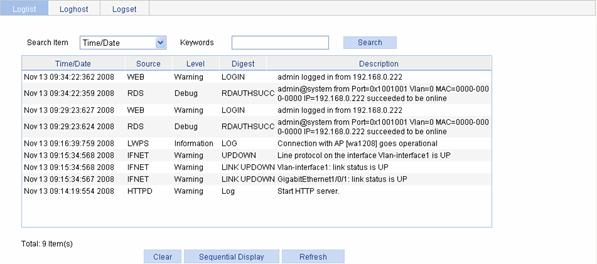
Table 4-3 describes the syslog display items.
Table 4-3 Syslog display items
|
Item |
Description |
|
Time/Date |
Displays the time/date when system logs are generated. |
|
Source |
Displays the module that generates system logs. |
|
Level |
Displays the severity level of system logs. For the detailed description of the severity levels, refer to Table 4-4. |
|
Digest |
Displays the brief description of system logs |
|
Description |
Displays the contents of system logs. |
You can perform the following operations in the syslog display page:
l Click Clear to clear the log buffer.
l Click Sequential Display to change the order in which system logs are displayed, and then the Sequential Display button will be changed to Reverse Display. After you change the order in which system logs are displayed, the system logs are displayed in this order, unless you change it again.
Table 4-4 System logs severity level
|
Severity level |
Description |
Value |
|
Emergency |
The system is unavailable. |
0 |
|
Alert |
Information that demands prompt reaction |
1 |
|
Critical |
Critical information |
2 |
|
Error |
Error information |
3 |
|
Warning |
Warnings |
4 |
|
Notification |
Normal information that needs to be noticed |
5 |
|
Informational |
Informational information to be recorded |
6 |
|
Debugging |
Information generated during debugging |
7 |
|
Note: A smaller value represents a higher severity level. |
||
Return to System logs configuration task list.
Setting Loghost
Select Device > Syslog from the navigation tree, and click the Loghost tab to enter the loghost configuration page, as shown in Figure 4-3.

Table 4-5 describes the loghost configuration item.
Table 4-5 Loghost configuration item
|
Item |
Description |
|
Loghost IP |
IP address of the loghost. l You can specify up to four loghosts. l You must input a valid IP address. l If you input a loopback address, for example 127.0.0.1, the system will not give any prompt, but your configuration will not take effect. |
Return to System logs configuration task list.
Back Up Configuration
Configuration backup provides the following functions:
l Open and view the configuration file (.cfg file or .xml file) for the next startup
l Back up the configuration file (.cfg file or .xml file) for the next startup to the host of the current user
Select Device > Configuration from the navigation tree at the left side of the interface to enter the backup configuration page, as shown in Figure 5-1.
Figure 5-1 Backup configuration page

l After you click the upper Backup button in this figure, a file download dialog box appears. You can select to view the .cfg file or to save the file locally.
l After you click the lower Backup button in this figure, a file download dialog box appears. You can select to view the .xml file or to save the file locally.
Restore Configuration
Configuration restore provides the following functions:
l Upload the .cfg file on the host of the current user to the device for the next startup
l Upload the .xml file on the host of the current user to the device for the next startup, and delete the previous .xml configuration file that was used for the next startup
Select Device > Configuration from the navigation tree at the left side of the interface, and then click the Restore tab to enter the configuration restore page, as shown in Figure 5-2.
Figure 5-2 Configuration restore page
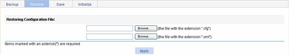
l After you click the upper Browse button in this figure, the file upload dialog box appears. You can select the .cfg file to be uploaded, and then click OK.
l After you click the lower Browse button in this figure, the file upload dialog box appears. You can select the .xml file to be uploaded, and then click OK.
Save Configuration
The save configuration module provides the function to save the current configuration to the configuration file (.cfg file or .xml file) for the next startup.
Select Device or Configuration from the navigation tree at the left side of the interface, and then click the Save tab to enter the save configuration confirmation page, as shown in Figure 5-3.
Figure 5-3 Save configuration confirmation
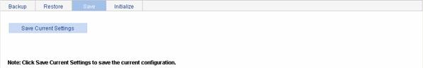
Click the Save Current Settings button to save the current configuration to the configuration file.
![]()
l Saving the configuration takes a period of time.
l The system does not support the operation of saving configuration of two or more consecutive users. If such a case occurs, the system prompts the latter users to try later.
Initialize
This operation will restore the system to factory defaults, delete the current configuration file, and reboot the device.
Select Device > Configuration from the navigation tree at the left side of the interface, and then click the Initialize tab to enter the initialize confirmation page as shown in Figure 5-4.
Figure 5-4 Initialize confirmation dialog box

Click the Restore Factory-Default Settings button to restore the system to factory defaults.
![]()
An access controller product has a factory default configuration when it is shipped. With this configuration, you can input http://192.168.0.100 in the address bar of the browser on a Web network management terminal (PC), supposing that a route between the Web network management terminal and the access controller product is available, and the browser will display the login page. Input the default username and password admin, select the language, and then you can log in to the Web interface.
Overview
Software upgrade allows you to obtain a target application file from the current host and set the file as the main boot file or backup boot file to be used at the next reboot.
A boot file, also known as the system software or device software, is an application file used to boot the device. A main boot file is used to boot a device and a backup boot file is used to boot a device only when the main boot file is unavailable.
Software Upgrade
Select Device > Software Upgrade from the navigation tree to enter the software upgrade configuration page, as shown in Figure 6-1.
Figure 6-1 Software upgrade configuration page

Table 6-1 shows the detailed configuration for software upgrade.
Table 6-1 Software upgrade configuration items
|
Item |
Description |
|
File |
Specifies the filename of the local application file, which must be with an extension .bin or .app. |
|
Filename |
Specifies a filename for the file to be saved on the device. The filename must have an extension, which must be the same as that of the source application file. |
|
File Type |
Specifies the type of the boot file for the next boot: l Main l Backup |
|
If the file with same name exists, overwrite it without remind. |
Specifies whether to overwrite the file with the same name. If you do not select the option, when a file with the same name exists, the system will pop up a dialog box asking whether to overwrite the existing file. |
|
Reboot after the upgrading finished. |
Specifies whether to reboot the device to make the upgraded software take effect after the application file is uploaded. |
![]()
Software upgrade takes some time. Do not perform any operation on the web interface during the upgrading procedure; otherwise, the upgrade operation will be interrupted.
![]()
There are many types of storage media such as flash, compact flash (CF), and universal serial bus (USB). The WX6000 series support CF card and USB; the WX5002 and the WX3000 series only support flash; the WX5004 supports CF card only.
Overview
The device saves useful files (such as host software, configuration file) into the storage device, and the system provides the file management function for the users to manage those files conveniently and effectively. File management function provides the following operations:
File Management Configuration
Displaying File List
Select Device > File Manage from the navigation tree at the left side of the interface to enter the file management page, as shown in Figure 7-1. This page displays all files saved on the storage device, and filenames are displayed in the format of path + filename.

Downloading a File
Select Device > File Manage from the navigation tree at the left side of the interface to enter the file management page, as shown in Figure 7-1. Select a file from the list, click the Download File button, and then a File Download dialog box appears. You can select to open the file or to save the file locally. You can download only one file at one time.
Uploading a File
Select Device > File Manage from the navigation tree at the left side of the interface to enter the file management page, as shown in Figure 7-1. You can type the file path and filename in the Upload File box at the bottom of the page, or click Browse to select a file, and then select a storage device from the drop-down list. Click Apply to upload the file to the specified storage device.
Removing a File
Select Device > File Manage from the navigation tree at the left side of the interface to enter the file management page, as shown in Figure 7-1. You can remove a file by using one of the following ways:
l
Click the ![]() icon to remove a file.
icon to remove a file.
l Select one or multiple files from the file list, and then click Remove File.
![]()
Before rebooting the device, save the configuration; otherwise, all unsaved configuration will be lost after device reboot. After the device reboots, you need to re-log in to the Web interface.
Select Device > Reboot from the navigation tree at the left side of the interface to enter the device reboot configuration page, as shown in Figure 8-1. Click Apply to reboot the device.

You can choose to check whether the current configuration has been saved to the configuration file to be used at the next startup.
l If you select the check box before “Check configuration with next startup configuration file”, the system will check the configuration before rebooting the device. If the check succeeds, the system will reboot the device; if the check fails, the system will pop up a dialog box to tell you that the current configuration and the saved configuration are inconsistent, and will not reboot the device. In this case, you need to save the current configuration manually before you can reboot the device.
l If you do not select the check box, the system will reboot the device directly.
Overview
In communications, an external interface (simply referred to as an interface defines a set of methods for two devices to exchange data and interact with each other. In the broad sense, interfaces fall into physical interfaces and logical interfaces. Physical interfaces are entities that physically exist and supported by components. Ethernet interfaces are an example of physical interfaces. Logical interfaces are interfaces created administratively or automatically by the system for data exchange but they do not exist in physical forms.
Interface management on the Web-based configuration interface is to manage all physical interfaces on your device and the following two types of logical interfaces:
l Loopback interfaces, that is, logical interfaces whose IP addresses are on the network segment 127.0.0.0. Loopback interfaces are used for receiving packets destined for the local device.
l Null interfaces, which are always up but can neither forward data packets nor be configured with an IP address or any link layer protocol. Any data packets sent to a null interface will be dropped.
l WLAN-ESS interfaces, which are virtual Layer 2 interfaces. A WLAN-ESS interface operates like a Layer 2 Ethernet access port. It has Layer 2 attributes and supports multiple Layer 2 protocols. In addition, a WLAN-ESS interface can also be used as a template for configuring WLAN-DBSS interfaces. WLAN-DBSS interfaces created on a WLAN-ESS interface adopt the configuration of the WLAN-ESS interface.
l WLAN-BSS interfaces, which are virtual Layer 2 interfaces. A WLAN-BSS interface operates like a Layer 2 Ethernet access port. It has Layer 2 attributes and supports multiple Layer 2 protocols. On a wireless router, a WLAN-Radio physical interface bound with a WLAN-BSS interface works in Layer 2 (bridge) mode.
l WLAN mesh interfaces, which are virtual Layer 2 interfaces. You can use a WLAN mesh interface as a configuration template to make and save settings made for WLAN mesh link interfaces. Once a WLAN mesh link interface is created, you will not be allowed to change the settings on its associated WLAN mesh interface.
l VLAN interfaces, which are virtual Layer 3 interfaces used for Layer 3 communications between VLANs. A VLAN interface corresponds to a VLAN. You can assign an IP address to a VLAN interface and specify it as the gateway of the corresponding VLAN to forward traffic destined for an IP network segment different from that of the VLAN.
l Virtual template (VT) interfaces, which are templates used for configuring virtual access (VA) interfaces.
l Bridge-Aggregation interfaces, which are Layer 2 aggregate interfaces used in link aggregation.
l Dialer interfaces, which are logical interfaces delivering dialup services.
Configuring Interface Management
Displaying Interface Information and Statistics
Select Device > Interface in the navigation tree to enter the page shown in Figure 9-1. The page displays the interfaces’ names, IP addresses, masks, and status. You can click an interface name in the Name column to display the statistics of that interface, as shown in Figure 9-2.
Figure 9-1 Interface management page
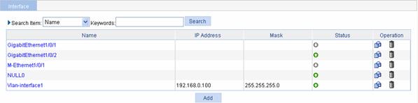
Figure 9-2 Statistics on an interface

Creating an Interface
Select Device > Interface in the navigation tree to enter the page shown in Figure 9-1. Click Add to enter the page for creating an interface.
Table 9-1 describes the configuration items of creating an interface.
Table 9-1 Configuration items of creating an interface
|
Item |
Description |
|
|
Interface Name |
Set the type and number of a logical interface. |
|
|
VID |
Set the VLANs associated with the Layer 3 subinterface. This parameter is available only after you set the interface name for a subinterface of a Layer-3 interface in the previous step.
Currently, this parameter is not configurable because the device does not support Layer 3 Ethernet subinterfaces. |
|
|
MTU |
Set the maximum transmit unit (MTU) of the interface. The MTU value affects fragmentation and reassembly of IP packets. This parameter can be configured only when the Interface Name field is set to Virtual-Template. |
|
|
TCP MSS |
Set the maximum segment size (MSS) for IP packets on the interface. The TCP MSS value affects fragmentation and reassembly of IP packets. This parameter can be configured only when the Interface Name field is set to Virtual-Template. |
|
|
IP Config |
None |
The modes to set IP addresses: l Not Set: IP address is not set. l Static Address: Select the option to manually assign an IP address and mask for the interface. l DHCP: Select the option for the interface to obtain an IP address through DHCP. l BOOTP: Select the option for the interface to obtain an IP address through BOOTP. l PPP Negotiate: Obtains an IP address through PPP negotiation l Borrowed Address: Borrows the IP address of another interface on the same device. |
|
Static Address |
||
|
DHCP |
||
|
BOOTP |
||
|
PPP Negotiate |
||
|
Unnumbered |
||
|
IP Address |
Set the IP address and subnet mask for the interface. Configure both items when Static Address is selected for the IP Config item, and configure only IP addresses for loopback interfaces. |
|
|
Mask |
||
|
Unnumbered Interface |
Set the interface whose IP address is to be borrowed. Configure this item when Borrowed Address is selected for the IP Config item. |
|
|
IPv6 Link Local config |
None |
The modes to set an IPv6 link local address, including: l None: No IPv6 link local address is set. l Auto: An IPv6 link local address is automatically generated. l Manual: Manually configure an IPv6 link local address. By default, an IPv6 link local address is generated when an interface is configured with an IPv6 unicast address. |
|
Auto |
||
|
Manual |
||
|
IPv6 unicast config |
IPv6 unicast address |
Set an IPv6 global unicast address or site-local address for an interface. |
|
EUI64 encoding |
Specify an IPv6 global unicast address or site local address in IEEE EUI-64 format. The prefix of the address is the specified prefix, and the interface identifier is converted from the MAC address of the interface. |
|
Editing an Interface
Select Device
> Interface in the navigation tree to
enter the page as shown in Figure
9-1, and then click the ![]() icon corresponding to an
interface to enter the Edit Interface page of the interface. For a Layer
2 physical port, the Edit Interface page
is shown in Figure 9-3, and the editing items are shown in Table 9-2. For configurations of ports of other types, refer to Table 9-2.
icon corresponding to an
interface to enter the Edit Interface page of the interface. For a Layer
2 physical port, the Edit Interface page
is shown in Figure 9-3, and the editing items are shown in Table 9-2. For configurations of ports of other types, refer to Table 9-2.
Figure 9-3 Edit a Layer 2 physical port
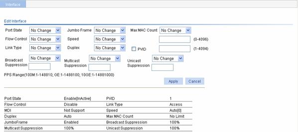
Table 9-2 Configuration items of editing a Layer 2 physical port
|
Item |
Description |
|
Port State |
Enables or disables the port. |
|
Flow Control |
Enables or disables flow control on the port. |
|
Link Type |
Sets the port’s link type, which can be access, hybrid or trunk. For more information about link types, refer to Table 9-3.
To change a trunk port to a hybrid port or vice versa, you need to change it to an access port first. |
|
Jumbo Frame |
Allows or forbids jumbo frames to pass through the port. |
|
Speed |
Set the port’s transmission rate: l 10: indicates 10 Mbps l 100: indicates 100 Mbps l 1000: indicates 1000 Mbps l Auto: indicates auto-negotiation |
|
Duplex |
Set the port’s duplex mode: l Auto: indicates auto-negotiation l Full: indicates full duplex l Half: indicates half duplex |
|
MAX MAC Count |
Sets the maximum number of MAC addresses the port can learn: l User Defined: the user needs to manually input the maximum number l No Limited: there is no limit on the number of MAC addresses that can be learned |
|
PVID |
Set the port’s default VLAN ID
l The trunk ports at the two ends of a link must have the same PVID. Otherwise, the link cannot properly transmit packets. l The hybrid ports at the two ends of a link must have the same PVID. Otherwise, the link cannot properly transmit packets. |
|
Broadcast Suppression |
Selects the parameter used in broadcast suppression and sets its value: l Ratio: indicates the maximum percentage of broadcast traffic to the total transmission capability of an Ethernet interface. When this parameter is selected, you need to provide a percentage in the box below. l PPS: indicates the maximum number of broadcast packets that can be forwarded on an Ethernet interface per second. When this parameter is selected, you need to provide a number in the box below. |
|
Multicast Suppression |
Selects the parameter used in multicast suppression and sets its value: l Ratio: indicates the maximum percentage of multicast traffic to the total transmission capability of an Ethernet interface. When this parameter is selected, you need to provide a percentage in the box below. l PPS: indicates the maximum number of multicast packets that can be forwarded on an Ethernet interface per second. When this parameter is selected, you need to provide a number in the box below. |
|
Unicast Suppression |
Selects the parameter used in unicast suppression and sets its value: l Ratio: indicates the maximum percentage of unicast traffic to the total transmission capability of an Ethernet interface. When this parameter is selected, you need to provide a percentage in the box below. l PPS: indicates the maximum number of unicast packets that can be forwarded on an Ethernet interface per second. When this parameter is selected, you need to provide a number in the box below. |
Table 9-3 Link type description
|
Link type |
Description |
|
Access |
An access port can belong to only one VLAN and is usually used to connect a user device. |
|
Hybrid |
A hybrid port can be assigned to multiple VLANs, receive and send packets of multiple VLANs, and allow packets of multiple VLANs to pass through untagged. It can be used to connect network devices, as well as user devices. |
|
Trunk |
A trunk port can be assigned to multiple VLANs, receive and send packets of multiple VLANs, but allows only packets of the default VLAN to pass through untagged. It is usually used to connect network devices. |
Shutting Down/Bringing Up an Interface
Select Device > Interface in the navigation tree to enter the page shown in Figure 9-1. By clicking the status icon of an interface, you can shut down the interface if it is currently up or bring up the interface if it is currently down.
The following three icons show the status of an interface:
l
![]() : indicates that the interface is up and
connected.
: indicates that the interface is up and
connected.
l
![]() : indicates that the interface is up but
disconnected.
: indicates that the interface is up but
disconnected.
l
![]() : indicates that the interface is down.
: indicates that the interface is down.
![]()
There are two kinds of port mirroring: local port mirroring and remote port mirroring. Only the WX5002 supports local port mirroring.
Introduction to Port Mirroring
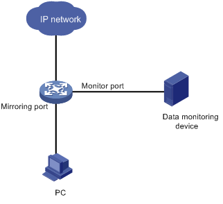
Port mirroring is to copy the packets passing through one or multiple ports (called mirroring ports) to a port (called the monitor port) on the local device. The monitor port is connected with a monitoring device. By analyzing on the monitoring device the packets mirrored to the monitor port, you can monitor the network and troubleshoot possible network problems.
Figure 10-1 A port mirroring implementation
Implementing Port Mirroring
Port mirroring is implemented through mirroring groups.
The mirroring ports and the monitor port are in the same mirroring group. With port mirroring enabled, the device copies packets passing through the mirroring ports to the monitor port.
Other Supported Features
Mirroring groups support inter-board mirroring, that is, the mirroring ports and the monitor port can be located on different boards.
Besides, you can use one monitor port to monitor multiple mirroring ports
![]()
Support for inter-board mirroring depends on your device model.
Configuring Port Mirroring
Configuration Task List
Follow the steps in Table 10-1 to configure port mirroring:
Table 10-1 Port mirroring configuration task list
|
Task |
Remarks |
|
Create a mirroring group |
Required Refer to section Creating a Mirroring Group for details. You need to select the mirroring group type local in the Type drop-down list. |
|
Configure the mirroring ports |
Required Refer to section Configuring Ports for a Mirroring Group for details. During configuration, you need to select the port type Mirror Port. |
|
Configure the monitor port |
Required Refer to section Configuring Ports for a Mirroring Group for details. During configuration, you need to select the port type Monitor Port. |
Creating a Mirroring Group
Select Device > Port Mirroring in the navigation tree and click the Create tab to enter the page for creating a mirroring port, as shown in Figure 10-2.
Figure 10-2 The page for creating a mirroring group
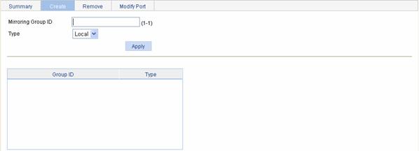
Table 10-2 describes the configuration items of creating a mirroring group.
Table 10-2 Configuration items of creating a mirroring group
|
Item |
Description |
|
Mirroring Group ID |
ID of the mirroring group to be created |
|
Type |
Specify the type of the mirroring group to be created: Local: Creates a local mirroring group. |
Return to Port mirroring configuration task list.
Configuring Ports for a Mirroring Group
Select Device > Port Mirroring in the navigation tree and click Modify Port to enter the page for configuring ports for a mirroring group, as shown in Figure 10-3.
Figure 10-3 The page for configuring ports for a mirroring group
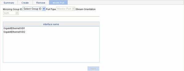
Table 10-3 describes the configuration items of configuring ports for a mirroring group.
Table 10-3 Configuration items of configuring ports for a mirroring group
|
Item |
Description |
|
Mirroring Group ID |
ID of the mirroring group to be configured The available groups were created in advance. |
|
Port Type |
Sets the types of the ports to be configured: l Monitor Port: configures the monitor port for the mirroring group. l Mirror Port: configures mirroring ports for the mirroring group. |
|
Stream Orientation |
Set the direction of the traffic monitored by the monitor port of the mirroring group This configuration item is available when Mirror Port is selected is the Port Type drop-down list. l both: Mirrors both received and sent packets on mirroring ports. l inbound: Mirrors only packets received by mirroring port. l outbound: Mirrors only packets sent by mirroring ports. Support for monitoring directions depends on you device model. |
|
interface name |
Select the ports to be configured from the interface name list. |
Return to Port mirroring configuration task list.
Configuration Examples
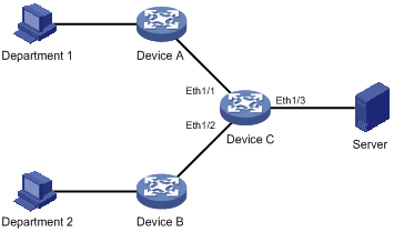
Network requirements
The customer network is as described below:
l Department 1 accesses Device C through Ethernet 1/1.
l Department 2 accesses Device C through Ethernet 1/2.
l Server is connected to Ethernet1/3 of Device C.
Configure port mirroring to monitor the bidirectional traffic of Department 1 and Department 2 on the server.
To satisfy the above requirement through port mirroring, perform the following configuration on Device C:
l Configure Ethernet1/1 and Ethernet 1/2 as mirroring ports.
l Configure Ethernet1/3 as the monitor port.
Figure 10-4 Network diagram for port mirroring configuration
Configuration procedure
# Create a mirroring group.
l Select Device > Port Mirroring in the navigation tree and click Create
l Type mirroring group ID 1.
l Select Local in the Type drop-down list.
l Click Apply to complete the operation.
# Configure the mirroring ports.
l Click Modify Port.
l Select 1 – Local in the Mirroring Group ID drop-down list.
l Select Mirror Port in the Port Type drop-down list.
l Select both in the Stream Orientation drop-down list.
l Select Ethernet 1/1 and Ethernet 1/2 in the interface name list.
l Click Apply to complete the operation.
l Select 1 – Local in the Mirroring Group ID drop-down list.
l Select Monitor Port in the Port Type drop-down list.
l Select Ethernet 1/3 in the interface name list.
l Click Apply to complete the operation.
Configuration Guidelines
When configuring port mirroring, note that:
l To ensure operation of your device, do not enable STP, MSTP, or RSTP on the monitor port.
l You can configure multiple mirroring ports but only one monitor port for a mirroring group.
l A port can be assigned to only one mirroring group.
Overview
In the user management part, you can:
l Set the username, password, and access level for an FTP or Telnet user.
l Set the super password for switching the current Web user level to the management level
l Switch the current Web user access level to the management level
Users
Creating a User
Select Device > Users from the navigation tree, and click the Create tab to enter the page for creating local users, as shown in Figure 11-1.
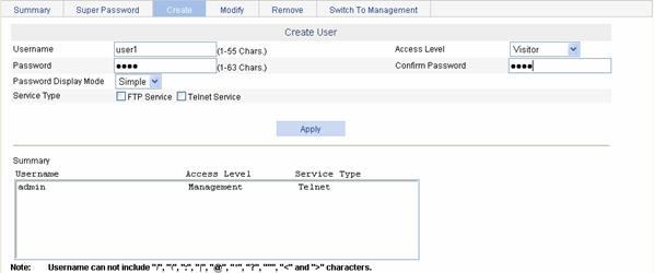
Table 11-1 describes the configuration items for creating a user.
Table 11-1 Configuration items for creating a user
|
Item |
Description |
|
Username |
Sets the username for a user. The username cannot include two or more successive spaces and the signs mentioned on the page. |
|
Access Level |
Sets the access level for a user. Users of different levels can perform different operations. Web user levels, from low to high, are visitor, monitor, configure, and management. l Visitor: Users of visitor level can only use the network diagnostic tool ping. They can neither access the device data nor configure the device. l Monitor: Users of this level can only access the device data but cannot configure the device. l Configure: Users of this level can access data on the device and configure the device, but they cannot upgrade the host software, add/delete/browse users, modify the passwords of other users, or restore the application file. l Management: Users of this level can perform any operations on the device. |
|
Password |
Sets the password for a user l When the password mode is Simple, the input password is in plain text. l When the password mode is Cipher, the input password is either in plain text or cipher text with a length of 24 or 88. In this case, the input plain password with the length smaller than or equal to 16 will be converted to a cipher password with a length of 24; the input plain password with a length greater than 16 but smaller than 63 will be converted to a cipher password with a length of 88. When the length of the input password is 24, if the system can decrypt the password, it considers the password as a ciphertext password; if not, the system considers the password as a plaintext password. When the length of the input password is 88, if the system can decrypt the password, it considers the password as a ciphertext password; if not, the system prompts that the password is invalid. |
|
Confirm Password |
Inputs the same password again. Otherwise, the system prompts that the two passwords input are not consistent when you apply the configuration. |
|
Password Display Mode |
Sets the password display mode. l Simple: The password will be saved in the configuration file in plain text. l Cipher: The password will be saved in the configuration file in cipher text, even if the password is input in plain text when configured. The plaintext password is not safe, and you are recommended to use the ciphertext password. No matter the password mode is set to Simple or Cipher, you must enter the password in the form of plain text for login authentication. |
|
Service Type |
Sets the service type, including FTP and Telnet services. You must select either of them. |
Setting the Super Password
In this part, users of the management level can specify the password for a lower-level user to switch from the current access level to the management level. If no such a password is configured, the switchover will fail.
Select Device > Users from the navigation tree, and click the Super Password tab to enter the super password configuration page, as shown in Figure 11-2.
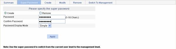
Table 11-2 describes the configuration items of specifying a super password.
Table 11-2 Super password configuration items
|
Item |
Description |
|
Create/Remove |
Sets the operation type: l Create: Configure or modify the super password. l Remove: Remove the current super password. |
|
Password |
Sets the password for a user to switch to the management level. |
|
Confirm Password |
Inputs the same password again. Otherwise, the system prompts that the two passwords input are not consistent when you apply the configuration. |
|
Password Display Mode |
Sets the password display mode. l Simple: The password will be saved in the configuration file in plain text. l Cipher: The password will be saved in the configuration file in cipher text. The plaintext password is not safe, and you are recommended to use the ciphertext password. |
Switching the User Access Level to the Management Level
This function is provided for a user to switch the current user level to the management level. Note the following:
l Before switching, make sure that the super password is already configured. A user cannot switch to the management level without a super password.
l The access level switchover of a user is valid for the current login only. The access level configured for the user is not changed. When the user re-logs in to the Web interface, the access level of the user is still the original level.
Select Device > Users from the navigation tree, and click the Switch To Management tab to enter the access level switching page, as shown in Figure 11-3. Type the super password and click Login.
Figure 11-3 Switch to the management level.

Overview
You can check whether an Ethernet port works normally by performing Ethernet port loopback test. During a loopback test, a port cannot forward data packets normally.
Ethernet port loopback test can be internal or external.
l In an internal loopback test, self loop is established in the switching chip to check whether there is a chip failure related to the port.
l In an external loopback test, a self-loop header is used on the port. Packets forwarded by the port will be received by itself through the self-loop header. The external loopback test can be used to check whether there is a hardware failure on the port.
Loopback Operation
Select Device > Loopback from the navigation tree to enter the loopback test configuration page, as shown in Figure 12-1.
Figure 12-1 Loopback test configuration page

Table 12-1 describes the loopback test configuration items.
Table 12-1 Loopback test configuration items
|
Item |
Description |
|
|
Testing type |
External |
Sets the loopback test type, which can be selected between External and Internal. Support for the test type depends on the device model. |
|
Internal |
||
|
Interface |
Specifies the Ethernet interface to have a loopback test. |
|
After the above configuration, click Test to start the loopback test, and you can see the test result at the right of the Test button.
Configuration Guidelines
Note the following when performing a loopback test:
l You can perform an internal loopback test but not an external loopback test for a port that is physically down, while you can perform neither test for a port that is manually shut down.
l The system does not allow Rate, Duplex, and Port Status configuration on a port under the loopback test.
l An Ethernet port works in the full duplex mode when the loopback test is performed, and restores its original duplex mode after the loopback test.