- Table of Contents
-
- H3C WX Series Access Controllers Web-Based Configuration Manual-6PW103
- 00-1Cover
- 01-Quick Start
- 02-Web Overview
- 03-Summary
- 04-Device
- 05-Network
- 06-AP Configuration
- 07-WLAN Service Configuration
- 08-WLAN Roaming Configuration
- 09-Radio Configuration
- 10-Authentication
- 11-Security
- 12-QoS
- 13-SNMP
- 14-Advanced Settings
- Related Documents
-
| Title | Size | Download |
|---|---|---|
| 11-Security | 617.12 KB |
Table of Contents
Taking Countermeasures Against Rogue Device Attacks
Configuring Rogue Device Detection
Configuring Detection Rule Lists
Enabling Countermeasures and Configuring Aging Time for Detected Rogue Devices
Rogue Detection Configuration Example
Displaying Statistics Information
6 User Isolation Configuration
Displaying User Isolation Information
User Isolation Configuration Example
l The sample Web page information in this manual was created on the WX5002. The Web page information on your device may vary.
l The models listed in this manual are not applicable to all regions. Please consult the local agents for the models applicable to your region.
Overview
802.11 networks are susceptible to a wide array of threats such as unauthorized access points and clients, ad hoc networks, and Denial of Service (DoS) attacks. Rogue devices are a serious threat to enterprise security. WLAN intrusion detection system (WIDS) is used for the early detection of malicious attacks and intrusions on a wireless network. Wireless intrusion prevention system (WIPS) helps to protect enterprise networks and users from unauthorized wireless access. The rogue detection feature is a part of the WIDS/WIPS solution, which detects the presence of rogue devices in a WLAN network and takes countermeasures to prevent rogue devices operation.
WLAN security provides such features as rogue detection, IDS attack detection, frame filtering, authorized IP, and user isolation.
Terminology
l WLAN intrusion detection system: WIDS is designed to be deployed in an area that an existing wireless network covers. It aids in the detection of malicious outsider attacks and intrusions via the wireless network.
l Rogue AP: An unauthorized or malicious access point on the network, such as an employee setup AP, misconfigured AP, neighbor AP or an attacker operated AP. As it is not authorized, if there is any vulnerability in the AP, the hacker will have chance to compromise your network security.
l Rogue client: An unauthorized or malicious client on the network.
l Rogue wireless bridge: Unauthorized wireless bridge on the network.
l Monitor AP: An AP that scans or listens to 802.11 frames to detect wireless attacks in the network. Some AP products work only in monitor role while some AP products could switch between normal AP role and monitor AP role.
l Ad hoc mode: Sets the working mode of a wireless client to ad hoc. An ad hoc terminal can directly communicate with other stations without support from any other device.
l Passive scanning: In passive scanning, a monitor AP listens to all the 802.11 frames over the air in that channel.
l Active scanning: In active scanning, a monitor AP, besides listening to all 802.11 frames, sends a broadcast probe request and receives all probe response messages on that channel. Each AP in the vicinity of the monitor AP will reply to the probe request. This helps identify all authorized and unauthorized APs by processing probe response frames. The monitor AP masquerades as a client when sending the probe request.
Detecting Rogue Devices
Rogue detection is applicable to large wireless networks. It detects the presence of rogue devices in a WLAN network based on the pre-configured rules.
Rogue detection can detect different types of devices in a WLAN network, for example, rogue APs, rogue clients, rogue wireless bridges, and ad-hoc terminals.
Taking Countermeasures Against Rogue Device Attacks
You can enable the countermeasures function on a monitor AP. The monitor AP downloads an attack list from the AC and takes countermeasures against the rogue devices based on the configured countermeasures mode. Then, the monitor AP sends fake de-authentication frames by using the MAC addresses of the rogue devices to remove them from the network.
Functionalities Supported
The rogue detection feature supports the following functionalities:
l RF monitoring in different channels
l Rogue AP detection
l Rogue client detection
l Ad hoc network detection
l Wireless bridge detection
l Countermeasures against rogue devices, clients and ad hoc networks
The current solution only supports detection of rogue devices managed by a single access controller.
The rogue detection feature does not support the following functionalities:
l Interfering AP (APs of other enterprises) detection
l Physical location tracking on wireless side
l Port location tracking and blocking on wire side
l DoS attacks against rogue APs
l Countermeasures against rogue wireless bridges
Configuring Rogue Device Detection
Perform the tasks in Table 2-1 to configure rogue detection.
Table 2-1 Rogue detection configuration task list
|
Task |
Remarks |
|
Required By default, the AP operates in normal mode and only provides WLAN data services. |
|
|
Required |
|
|
Enabling Countermeasures and Configuring Aging Time for Detected Rogue Devices |
Optional |
Configuring AP Operating Mode
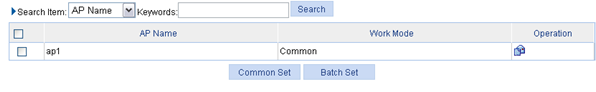
Select Security > Rogue Detection from the navigation tree, and then select the AP Monitor tab to enter the AP monitor configuration page as shown in Figure 2-1.
Figure 2-1 AP monitor configuration
Select the AP to be configured and click
the icon ![]() to
enter the configuration page as shown in Figure 2-2.
to
enter the configuration page as shown in Figure 2-2.
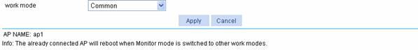
Figure 2-2 AP operating mode configuration
A WLAN consists of various APs that span across the building and offer WLAN services to the clients. The administrator may want some of these APs to detect rogue devices. The administrator can configure an AP to operate in any of the three modes, normal, monitor, and hybrid.
Table 2-2 describes the configuration items for configuring AP operating mode.
Table 2-2 AP operating mode configuration items
|
Item |
Description |
|
Work mode |
Configure the AP operating mode: l In common mode, an AP provides WLAN data services but does not perform scanning. l In monitor mode, an AP scans all Dot11 frames in the WLAN, but cannot provide WLAN services. l In hybrid mode, an AP can both scan devices in the WLAN and provide WLAN data services.
l When an AP has its operating mode changed from other operating modes to monitor, it does not restart. l When an AP has its operating mode changed from monitor to other, it restarts. |
Configuring Detection Rules
l Check whether an AP is a rogue.
Figure 2-3 Check whether an AP is a rogue

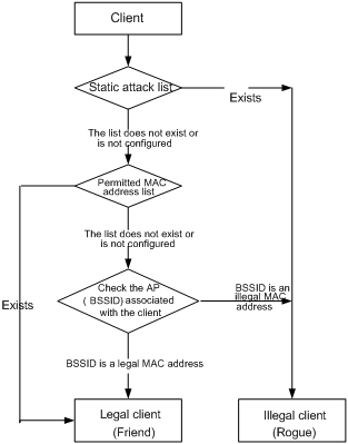
l Check whether a client is a rogue.
Figure 2-4 Check whether a client is a rogue
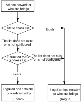
l Check whether an ad hoc network or a wireless bridge is a rogue.
Figure 2-5 Check whether an ad hoc network or a wireless bridge is a rogue
Configuring Detection Rule Lists
Select Security > Rogue Detection from the navigation tree, and then select the Rule List tab to enter detection rule list configuration page, as shown in Figure 2-6.
Figure 2-6 Rule list configuration
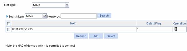
Table 2-3 describes the rule list configuration items.
Table 2-3 Rule list configuration items
|
Item |
Description |
|
List Type |
l MAC: You can add MAC addresses to be permitted after selecting this option. l Wireless Service: You can add SSIDs to be permitted after selecting this option. l Vendor: You can specify vendors to be permitted after selecting this option. l Attacker: You can add the MAC address of a device to configure the device as a rogue. |
Select MAC from the drop-down list and click Add to enter the MAC address configuration page, as shown in Figure 2-7.
Figure 2-7 MAC address list configuration page
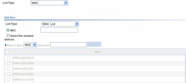
Table 2-4 describes configuration items for configuring MAC address list.
Table 2-4 MAC address list configuration items
|
Item |
Description |
|
MAC |
Type the permitted MAC address in the text box. |
|
Select the existent devices |
If you select this button, the MAC address table displays MAC addresses of the current devices. Select the MAC addresses to be permitted. |
The operation to add other types of lists is similar to the add operation of a MAC address list, and thus the description is omitted.
Enabling Countermeasures and Configuring Aging Time for Detected Rogue Devices
Select Security > Rogue Detection from the navigation tree, and then select the AP Monitor tab. On the page, click Common Set to enter the configuration page, as shown in Figure 2-8.
Figure 2-8 Common configuration
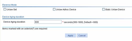
Table 2-5 describes the common configuration items.
Table 2-5 Common configuration items
|
Item |
Description |
|
Reverse Mode |
l Unlaw Set: Allows you to take countermeasures against rogue devices . l Unlaw Adhoc Device: Allows you to take countermeasures against ad hoc devices. l Static Unlaw Device: Allows you to take countermeasures against static configured rogue devices. |
|
Device Aging-Duration |
Configure the aging time of entries in the device list. Once a rogue device is detected, an entry for it is added to the monitor record and the aging time starts. The aging time restarts if the device is detected again during the time. When the aging time is reached, the entry is deleted from the monitor record and added to the history record. |
Displaying Monitor Record
Select Security > Rogue Detection from the navigation tree, and then select the Monitor Record tab to enter the monitor record page, as shown in Figure 2-9.
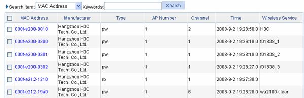
Table 2-6 describes the type item of monitor record.
Table 2-6 Type item of monitor record
|
Item |
Description |
|
Type |
l r: Rogue device. l p: Permitted device. l a: Ad hoc device. l w: AP. l b: Wireless bridge. l c: Client. For example, pw represents a permitted AP while rb represents a rogue wireless bridge. |
Displaying History Record
Select Security > Rogue Detection from the navigation tree, and then select the History Record tab to enter the history record page, as shown in Figure 2-10.
Figure 2-10 History record page
Rogue Detection Configuration Example
Network requirements
As shown in Figure 2-11, a monitor AP (AP 2) and AP 1 which provides WLAN service are connected to an AC through a Layer 2 switch.
l AP 1 operates in normal mode and provides WLAN data services only.
l AP 2 operates in monitor mode, and scans all Dot11 frames in the WLAN.
l Client 1 (MAC address 000f-e215-1515), Client 2 (MAC address 000f-e215-1530), and Client 3 (MAC address 000f-e213-1235) are connected to AP 1. They are configured as friends.
l Client 4 (MAC address 000f-e220-405e) is connected to AP 2. It is configured as a rogue device.
Figure 2-11 Rogue detection configuration

Configuration procedure
1) Configure AP 1 to operate in normal mode.
In normal mode, AP 1 provides WLAN data services only. For how to configure WLAN services, refer to Access Service Configuration.
2) Configure AP 2 to operate in monitor mode.
# Add an AP.
Select AP > AP Setup from the navigation tree to enter the configuration page. Click Create to enter the AP setup page as shown in Figure 2-12.
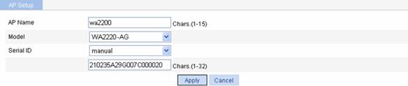
l Configure the AP name as wa2200.
l Select WA2220-AGfor the model.
l Select manual and type the serial ID of AP 2.
l Click Apply.
# Configure AP 2 to operate in monitor mode.
Select Security > Rogue Detection from the navigation tree, and
then select the AP Monitor tab to enter the AP monitor configuration page. Select the AP to be
configured and click the ![]() icon to enter the operating
mode configuration page as shown in Figure 2-13.
icon to enter the operating
mode configuration page as shown in Figure 2-13.
Figure 2-13 AP operating mode configuration
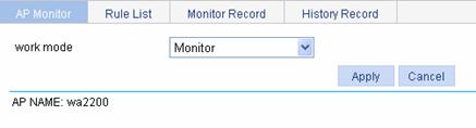
l Select Monitor as the operating mode.
l Click Apply.
# Enable the Dot11g radio mode.
Select Radio > Radio Setup from the navigation tree to enter the AP radio configuration page, as shown in Figure 2-14.
Figure 2-14 Radio configuration

l Select the AP with the radio mode to be enabled (wa2200 with Dot11g in this example), and then select the check box before the AP name.
l Click Enable.
3) Configure rogue detection rules.
Select Security > Rogue Detection from the navigation tree, and then select the Rule List tab to enter the rule list configuration page. Then click Add.
l Select MAC as the list type and type 000f-e215-1515, 000f-e215-1530, and 000f-e213-1235 in the MAC address text box.
l Select Attacker as the list type and type 000f-e220-405e in the text box.
l Click Apply.
4) Enable countermeasures against the static rogue device.
Select Security > Rogue Detection from the navigation tree, and then select the AP Monitor tab. On the page, click Common Set to enter the common configuration page, as shown in Figure 2-15.
Figure 2-15 Common configuration
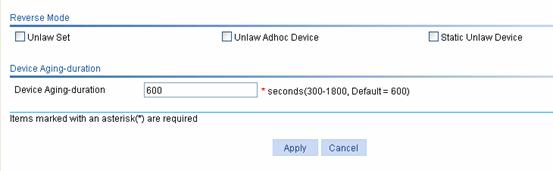
l Select the Static Unlaw Device check box. This is because the MAC address of Client 4 is added manually to the attacker list.
l Click Apply.
Configuration Guidelines
l The radio must be disabled so that the AP operation mode can be changed.
l If you configure more than one detection rule, you need to specify the rogue device types (AP, client, bridge, and ad hoc) and the rule matching order. For detailed information, refer to section "Configuring Detection Rules" on page 2-3.
l The wireless service configuration is needed for an AP operating in hybrid mode so that clients can connect to the AP; the wireless service configuration is not needed for an AP in monitor mode.
The IDS attack detection function detects intrusions or attacks on a WLAN network, and informs the network administrator of the attacks through recording information or sending logs. At present, IDS detection supports detection of the following attacks:
l Flood attack
l Spoofing attack
l Weak IV attack
Flood Attack Detection
Flood attack refers to the case where WLAN devices receive large volumes of frames of the same kind within a short span of time. When this occurs, the WLAN devices are overwhelmed with frames from this device and consequently, frames from authorized stations get dropped.
IDS attacks detection counters this flood attack by constantly keeping track of the density of traffic generated by each device. When this density exceeds the tolerance limit, the device is reported to be flooding the network and will be blocked. Subsequent frames from this device will not be processed. If the dynamic blacklist feature is enabled, the detected device is added to the blacklist.
IDS detects the following types of frames:
l Authentication requests and de-authentication requests
l Association requests, disassociation requests and reassociation requests
l Probe requests
l Null data frames
l Action frames.
When an AP supports multiple BSSIDs, stations send probe request frames to the individual BSSIDs. Therefore, to track the density of probe request frames, both the source and destination addresses are considered. For other frame types, only the source address is considered.
Spoofing Attack Detection
In this kind of attack, a potential attacker can send a frame in the air on behalf of another device. For instance, a spoofed de-authentication frame can cause a station to get de-authenticated from the network.
WIDS IPS counters this attack by detecting broadcast de-authentication and disassociation frames. When such a frame is received, this is identified as a spoofed frame, and the attack is immediately logged.
Weak IV Detection
Wired Equivalent Privacy (WEP) uses an Initialization Vector (IV) to encrypt each frame .WEP is based on a shared secret key and a pseudo-randomly generated 3-byte sequence. When a WEP frame is sent, the IV used in encrypting the frame is also sent as part of the frame header.
However, sending some classes of IVs can ultimately reveal the shared secret key to any potential attackers. When the shared secret key is compromised, the attacker can access network resources.
WIDS IPS counters this attack by verifying the IVs in WEP frames. Whenever a frame with a weak IV is detected, the attack is immediately logged.
Configuring IDS
Configuring IDS
Select Security > IDS from the navigation tree, and then select the IDS Setup tab to enter the IDS configuration page, as shown in Figure 3-1.

Table 3-1 describes the IDS configuration items.
Table 3-1 IDS configuration items
|
Item |
Description |
|
Flood Attack Detect |
If you select the check box, flood attack detection is enabled. It is disabled by default. |
|
Spoof Attack Detect |
If you select the check box, spoofing attack detection is enabled. It is disabled by default. |
|
Weak-iv Attack Detect |
If you select the check box, Weak IV attack detection is enabled. It is disabled by default. |
Displaying History Record
Select Security > IDS from the navigation tree, and then select the History Record tab to enter the history information page, as shown in Figure 3-2.
Figure 3-2 History information

Displaying Statistics Information
Select Security > IDS from the navigation tree, and then select the Statistics tab to enter the statistics information page, as shown in Figure 3-3.
Figure 3-3 Statistics information

An AC maintains a white list (Entries in the list will be permitted and can be configured through CLI), a static blacklist (Entries in the list will be denied and can be configured through CLI), and a dynamic blacklist (Entries in the list will be denied and are added when WLAN IDS detects flood attacks).
Frame Filtering maintains three types of list.
l Whitelist: Contains MAC addresses of stations whose frames can be processed. This list is configured by the user.
l Static blacklist: Contains MAC addresses of stations whose frames should be dropped. This list is configured by the user.
l Dynamic blacklist: Contains MAC addresses of stations whose frames should be dropped. An entry is dynamically added to the list by WLAN IDS when it detects a station sending a flood of frames.
Filtering will be carried out as follows:
l Whenever a frame is received by an AP, the input MAC address is checked.
l If the input MAC address does not match any entry in the white list, it is dropped.
l If no white list entries exist, the static and dynamic blacklist entries are searched.
l If the input MAC address does not match any of the entries in the lists, the frame is further processed. Otherwise, it is dropped.
l When no entries are present in the frame filter lists, all frames will be permitted.
Configuring Frame Filtering
Configuring Dynamic Blacklist
Select Security > Filter from the navigation tree, and then select the Blacklist tab to enter the dynamic blacklist configuration page, as shown in Figure 4-1.
Figure 4-1 Dynamic blacklist configuration page

Table 4-1 describes the configuration items for configuring dynamic blacklist.
Table 4-1 Dynamic blacklist configuration items
|
Item |
Description |
|
Dynamic Blacklist |
l Enable: Enables dynamic blacklist. l Disable: Disables dynamic blacklist.
Before enabling dynamic blacklist, select the Flood Attack Detect check box on the IDS configuration page. |
|
Lifetime |
Configure the lifetime of the entries in the blacklist. |
Configuring Static Blacklist
On the blacklist configuration page as shown in Figure 4-1, select the Static tab to enter the static blacklist configuration page, as shown in Figure 4-2. Click Add Static to enter the static blacklist configuration page.
Figure 4-2 Static blacklist configuration
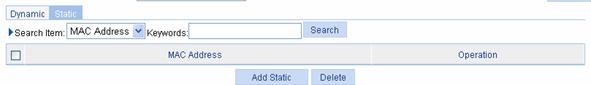
Table 4-2 describes static blacklist configuration items.
Table 4-2 Static blacklist configuration items
|
Item |
Description |
|
MAC Address |
Add a MAC address to the static black list. |
Configuring White List
Select Security > Filter from the navigation tree, and then select the Whitelist tab. Click Add to enter the white list configuration page, as shown in Figure 4-3.
Figure 4-3 White list configuration
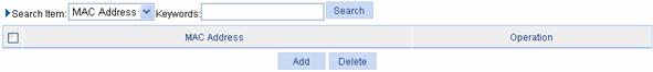
Table 4-3 describes the white list configuration items.
Table 4-3 White list configuration items
|
Item |
Description |
|
MAC Address |
Add a MAC address to the white list. |
Overview
The authorized IP function is to associate the HTTP or Telnet service with an ACL to filter the requests of clients. Only the clients that pass the ACL filtering can access the device.
Configuring Authorized IP
Before configuring authorized IP, you need to create and configure the ACL. For detailed configuration, refer to ACL IPv4 or ACL IPv6 section in the QoS part.
Select Security > Authorized IP from the navigation tree at the left side of the interface, and then click the Setup tab to enter the authorized IP configuration page, as shown in Figure 5-1.
Figure 5-1 Authorized IP configuration
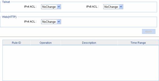
Table 5-1 describes the authorized IP configuration items.
Table 5-1 Authorized IP configuration items
|
Item |
Description |
|
|
Telnet |
IPv4 ACL |
Associates the Telnet service with an IPv4 ACL. Select an IPv4 ACL from the drop-down box. You can configure the IPv4 ACLs to be selected by selecting QoS > ACL IPv4. |
|
IPv6 ACL |
Associates the Telnet service with an IPv6 ACL. Select an IPv6 ACL from the drop-down box. You can configure the IPv6 ACLs to be selected by selecting QoS > ACL IPv6. |
|
|
Web (HTTP) |
IPv4 ACL |
Associates the HTTP service with an IPv4 ACL. Select an IPv4 ACL from the drop-down box. You can configure the IPv4 ACLs to be selected by selecting QoS > ACL IPv4. |
Overview
Without user isolation, all the users in the same VLAN can communicate with each other directly. To address the security issues this brings forth, wireless user isolation was designed, which aims to isolate clients in a VLAN from one other to ensure the security of user services while allowing them to access the Internet.
To achieve this purpose, an AC maintains a user isolation table containing a list of permitted MAC addresses for each VLAN. The unicasts sent to and received from these permitted MAC addresses are allowed to pass. When the AC receives a unicast sent from a station (a wireless client or PC) to another station in the same VLAN, it allows the packet to pass or drops the packet depending on the user isolation table. Note that the isolation does not apply to the broadcasts and multicasts in a VLAN. In addition, even after being isolated, a station can communicate with its gateway so long as the MAC address of the gateway is permitted.
User Communication
As shown in Figure 6-1, before user isolation is enabled in VLAN 2 on the AC, Client A and Client B in the VLAN can communicate with each other and access the Internet.
User Isolation
As shown in Figure 6-2, Client A and Client B are located in the same VLAN and they access the Internet through the gateway. Configure user isolation in VLAN 2 on the AC, and permit only the MAC address of the gateway. After that, Client A and Client B in VLAN 2 are isolated from each other as none of their MAC addresses are permitted on the AC, as shown by the red lines in the figure. However, both of them can access the Internet.
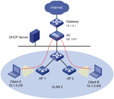
When the AC receives unicast packets sent between Client A or Client B and the gateway, it determines whether they can be forwarded according to the MAC address (source or destination) and VLAN ID in them. As the MAC address of the gateway is permitted, the AC will allow packets sent to and received from the gateway to pass. Thus, both Client A and Client B can access the Internet.
At the same time, as the MAC addresses of Client A and Client B are not permitted, the AC will not allow the packets sent between Client A and Client B to pass. Thus, Client A and Client B are isolated from each other even if they are in the same VLAN.
Configuring User Isolation
Displaying User Isolation Information
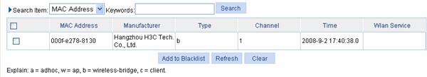
Select Security > User Isolate from the navigation tree to enter the page shown in Figure 6-3.
Figure 6-3 Display user isolation information

Select VLAN ID or MAC address from the Search Item drop-down list, and enter a keyword to display all user isolation entries that match this keyword.
Configuring User Isolation
Select Security > User Isolate from the navigation tree to enter the page shown in Figure 6-3, and then click Add to enter the page shown in Figure 6-4.
Figure 6-4 Configure user isolation
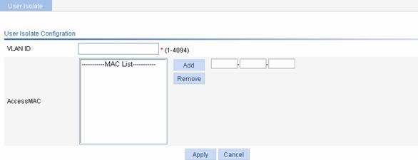
Table 6-1 lists the user isolation configuration items.
Table 6-1 User isolation configuration items
|
Item |
Description |
|
VLAN ID |
IDs of VLANs in which User Isolation needs to be enabled |
|
Access MAC |
Adds the MAC addresses of users that are allowed to pass: l Type the user MAC addresses in the box on the right. l Click Add to add the MAC addresses to the permitted MAC address list. l To remove a MAC address from the list, select the MAC address in the list and click Delete. |
![]()
You can configure a maximum of 16 MAC addresses in the permitted MAC address list of a VLAN.
User Isolation Configuration Example
Network requirements
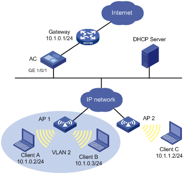
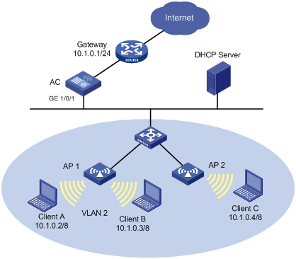
As shown in Figure 6-5, configure wireless clients Client A, Client B, and Client C in VLAN 2 such that they can all access the Internet, but cannot communicate with each other. The gateway’s default IP address is 10.1.0.1/24, MAC address is 000f-e212-7788.
Figure 6-5 Network diagram for user isolation configuration
Configuration procedure
1) Configure an IP address for the interfaces. Omitted
2) Configure user isolation in VLAN 2, and add the gateway’s MAC address to the user isolation table, so as to ensure that VLAN 2 users can access the Internet.
l Select Security > User Isolate from the navigation tree, and then click Add in the displayed page.
l Type 2 in the VLAN ID box.
l Add MAC address 000f-e212-7788 to the permitted MAC address list.
l Click OK to complete the operation.