- Table of Contents
-
- H3C WX Series Access Controllers Web-Based Configuration Manual-6PW103
- 00-1Cover
- 01-Quick Start
- 02-Web Overview
- 03-Summary
- 04-Device
- 05-Network
- 06-AP Configuration
- 07-WLAN Service Configuration
- 08-WLAN Roaming Configuration
- 09-Radio Configuration
- 10-Authentication
- 11-Security
- 12-QoS
- 13-SNMP
- 14-Advanced Settings
- Related Documents
-
| Title | Size | Download |
|---|---|---|
| 08-WLAN Roaming Configuration | 579.01 KB |
Table of Contents
WLAN Roaming Configuration Examples
Intra-AC Roaming Configuration Example
Inter-AC Roaming Configuration Examples
l The sample web page information in this manual was created on the WX5002. The Web page information on your device may vary.
l The models listed in this manual are not applicable to all regions. Please consult the local agents for the models applicable to your region.
The following table shows the support of the H3C WX series access controller products for features:
|
Feature |
WX5000 series |
WX6000 series |
WX3000 series |
||||||
|
WX5002 |
LS8M1WCMA0 |
WX5004 |
WX6103 |
LSQM1WCMB0 |
LSBM1WCM2A0 |
WX3024 |
WX3010 |
WX3008 |
|
|
IPv6 roaming |
Supported |
Supported |
Supported |
Supported |
Supported |
Supported |
Not supported |
Not supported |
Not supported |
Overview
The Inter AC Tunneling Protocol (IACTP) is a proprietary protocol of H3C which defines how access controllers (ACs) communicate with each other. IACTP provides a generic encapsulation and transport mechanism between ACs to provide secure AC-AC communications based on the standard TCP client/server model.
A mobility group is a group of ACs that communicate with each other through the IACTP protocol. A maximum of 8 ACs can be present in a mobility group in current version. Formation and maintenance of a mobility group are done by using IACTP.
IACTP provides a control tunnel for applications such as roaming to share/exchange messages. It also provides a data tunnel to encapsulate data packets to be transported between ACs. It can be used either with IPv4 or with IPv6.
Whenever a fast-roam capable station associates to any of the ACs in a mobility group (which would be it’s Home-AC (HA)) for the first time, it will go through 802.1X authentication followed by 11 Key exchange. The station information will be synchronized across the ACs in the mobility group prior to the roaming of the station within an AC/across ACs. When this station roams to another AC in the mobility group (which would be its Foreign-AC (FA)), the station information is used to fast authenticate the station by skipping 802.1X authentication, and performing only 802.11 key exchange to facilitate seamless roaming within the mobility group.
Terminology
l HA: The AC to which a wireless station is connected by associating with an AP for the first time is the HA of the station.
l FA: An AC that is other than the HA and to which a station is currently connected is an FA of the station.
l Fast-roam capable station: A wireless station which directly associates to a fast-roam service (RSN+Dot1x) with one AC for the first time.
l Roam-out station: A wireless station which has associated with an AC other than the HA in the mobility-group is referred to as a roam-out station at its HA.
l Roam-in station: A wireless station which has associated with an AC other than the HA in the mobility-group is referred to as a roam-in station at the FA.
l Intra-AC roaming: A procedure where a wireless station roams from one AP to another AP, which are connected to the same AC.
l Inter-AC roaming: A procedure where a wireless station roams from one AP to another AP, which are connected to different ACs.
l Inter-AC fast roaming capability: If a station uses 802.1x (RSN) authentication through negotiation, this station has inter-AC fast roaming capability.
l WLAN-tunnel: One type of layer 2 interface which is bound with an IACTP data tunnel and used to tunnel unicast/broadcast frames between ACs.
WLAN Roaming Topologies
WLAN Roaming topologies consist of:
l Intra-AC roaming topology
l Inter-AC roaming topology
l Intra-FA roaming topology
l Inter-FA roaming topology
l Roam-back topology
Intra-AC roaming
Figure 1-1 Intra-AC roaming
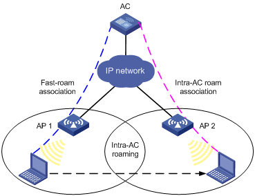
1) A station is associated with AP1 connected to an AC through fast-roam association.
2) The station disassociates with AP 1 and roams to AP 2 connected to the same AC.
3) The station is associated with AP 2 through intra-AC roam association.
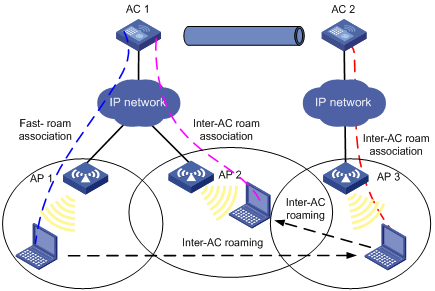
Inter-AC roaming
Figure 1-2 Inter-AC roaming
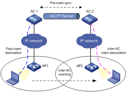
1) A station is associated with AP1 connected to AC1 through fast-roam association.
2) The station disassociates with AP1 and roams to AP2 connected to AC2.
3) The station is associated with AP2 through inter-AC roam association. Prior to inter-AC roaming, AC1 should synchronize the station information with AC2 through an IACTP tunnel.
Intra-FA roaming
Figure 1-3 Intra-FA roaming
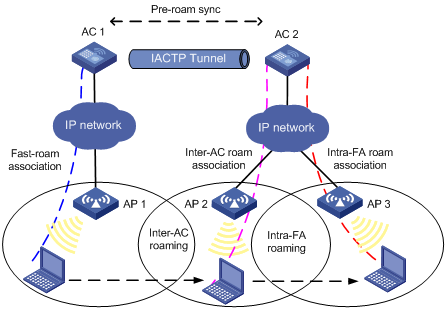
2) A station is associated with AP1 connected to AC1 through fast-roam association.
3) The station disassociates with AP1 and roams to AP2 connected to AC2. Now AC2 is the FA for the station.
4) The station is associated with AP2 through inter-AC roam association. Prior to inter-AC roaming, AC1 should synchronize the station information with AC 2 through an IACTP tunnel.
5) The station then disassociates with AP2 and roams to AP3 which is also connected to AC2. The station is associated with AP3 through intra-FA roam association.
Inter-FA roaming
Figure 1-4 Inter-FA roaming
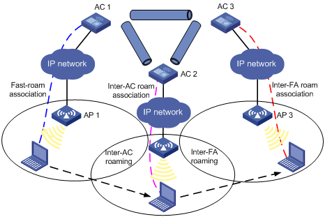
1) A station is associated with AP1 connected to AC1 through fast-roam association.
2) The station disassociates with AP1 and roams to AP2 connected to AC 2. Now AC2 is the FA for the station.
3) The station is associated with AP 2 through inter-AC roam association.
4) The station then disassociates with AP2 and roams to AP3 which is connected to AC3, which now is its FA. Prior to inter-AC roaming, AC1 should synchronize the station information with AC 2 and AC 3 through IACTP tunnels.
Roam-back
Figure 1-5 Roam-back
1) A station is associated with AP1 connected to AC1 through fast-roam association.
2) The station disassociates with AP1 and roams to AP3 connected to AC 2. Now AC2 is the FA for the station.
3) The station is associated with AP3 through inter-AC roam association. Prior to inter-AC roaming, AC1 should synchronize the station information with AC2 through an IACTP tunnel.
4) The station then disassociates with AP3 and roams back to AP2 connected to AC1, which is its HA.
Configuring WLAN Roaming
Configuring a Roaming Group
Select Roam > Roam Group from the navigation tree to enter the page for configuring a roaming group, as shown in Figure 1-6:
Figure 1-6 Configure a roaming group
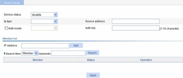
Table 1-1 describes the configuration items for configuring a roaming group.
Table 1-1 Configuration items for configuring a roaming group
|
Item |
Description |
|
Service status |
l enable: Enables the IACTP service. l disable: Disables the IACTP service. |
|
IP type |
Select IPv4 or IPv6 |
|
Source address |
Source address of the IACTP protocol |
|
Auth mode |
Select the check box before Auth mode, and select the MD5 authentication mode. |
|
Auth key |
Input an authentication key. |
![]()
l ACs in a roaming group must have the same user profile configured; otherwise, WLAN roaming may fail.
l ACs in a roaming group cannot be configured to work in AC hot backup mode.
Adding a Group Member
Select Roam > Roam Group from the navigation tree to enter the page for adding a group member, as shown in Figure 1-6:
Table 1-2 describes the configuration items for adding a group member.
Table 1-2 Configuration items for adding a group member
|
Item |
Description |
|
IP address |
Add the IP address of an AC to a roaming group. |
Displaying Client Information
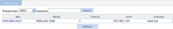
Select Roam > Roam Client from the navigation tree to enter the page shown in Figure 1-7.
![]()
The page you enter by selecting Roam > Roam Client shows the inter-AC roaming information of clients, if any.
Figure 1-7 Display client information
WLAN Roaming Configuration Examples
Intra-AC Roaming Configuration Example
Network requirements
As shown in the figure below, an AC has two APs associated and all of them are in VLAN 1. A client is associated with AP1. It is required to configure intra-AC roaming so that the client can associate with AP2 when roaming to AP2.
Figure 1-8 Intra-AC roaming
Configuration procedure
![]()
If remote authentication is needed in the authentication mode you select, you need to configure the RADIUS server. For how to configure the RADIUS server, refer to Authentication.
1) Configure APs
# Create two APs.
Select AP > AP Setup from the navigation tree, and then click New.
l Set the AP name to wa2200.
l Select the AP model WA2220-AG.
l Select the serial ID as manual, and type the serial ID of the AP.
l Click Apply.
Follow the above steps to create the other AP wa2600.
2) Configure wireless service
# Create a wireless service.
Select Wireless Service > Access Service from the navigation tree, and click New.
l Set the wireless service name to Roam.
![]()
You can implement intra-AC roaming using any of the authentication modes. For the configuration of the authentication modes, refer to Wireless Service. Note that fast roaming can be performed only when the RSN+Dot1x authentication mode is adopted.
l Click Apply.
# Enable the wireless service.
Select Wireless Service > Access Service from the navigation tree, select Roam, and then click Enable.
3) Bind an AP radio to a wireless service
Select Wireless Service > Access Service from the navigation tree, and click Bind at the right side of the wireless service Roam to enter the page for binding an AP radio, as shown in Figure 1-9:
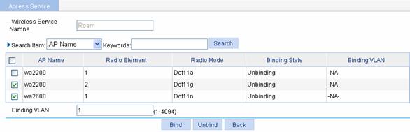
l Select the check boxes before wa2200 with radio type being Dot11g and before wa2600.
l Input VLAN 1 in the text box after Binding VLAN.
l Click Bind.
4) Enable dot11g radio
Select Radio > Radio Setup from the navigation tree to enter the radio setup page, as shown in Figure 1-10:
Figure 1-10 Enable dot11g radio
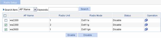
l Select the check box before wa2200 with the radio mode being Dot11g.
l Click Enable.
Configuration verfication
1) Method 1
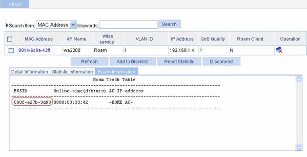
Select Summary > Client from the navigation tree, select the Roam Information tab, and click the target client to enter the page as shown in Figure 1-11. Then you can view the client roaming information.
From the roaming information, you can see that the client accesses the wireless network through wa2200, whose BSSID is 000f-e27b-3d90.
Figure 1-11 Client status before intra-AC roaming
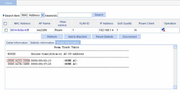
After intra-AC roaming, you can see from the roaming information that the client accesses the wireless network through wa2600, whose BSSID is 000f-e233-5500.
Figure 1-12 Client status after intra-AC roaming
2) Method 2
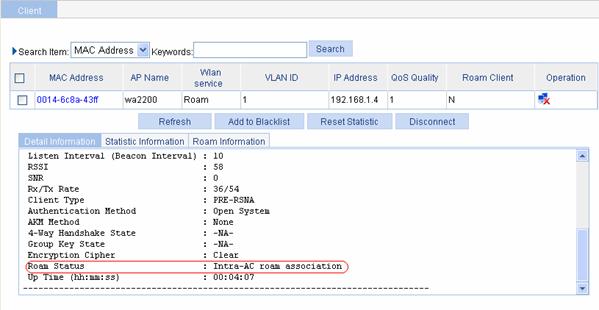
Select Summary > Client from the navigation tree, click the Detail Information tab, and click the target client to enter the page as shown in Figure 1-13. Then you can see that Intra-AC roam association is displayed for the Roam Status field.
Figure 1-13 Intra-AC roaming verification
Configuration guidelines
The SSID of the two APs should be the same for intra-AC roaming, that is, the same wireless service should be bound with two AP’s radios in Bind an AP radio to a wireless service.
Inter-AC Roaming Configuration Examples
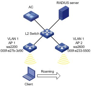
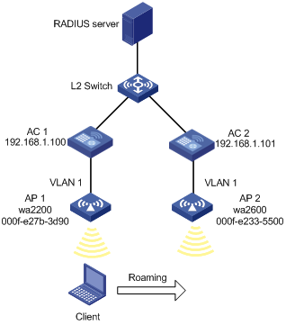
Network requirements
As shown in the figure below, two ACs that each are connected to an AP are connected through a Layer 2 switch. Both ACs are in the same network. The IP address of AC 1 is 192.168.1.100 and that of AC 2 is 192.168.1.101. A client associates with AP 1. It is required to configure inter-AC roaming so that the client can associate with AP 2 when roaming to it.
Figure 1-14 Inter-AC roaming
Configuration procedure
![]()
If remote authentication is needed in the authentication mode you select, you need to configure the RADIUS server. For how to configure the RADIUS server, refer to Authentication.
1) Establish a CAPWAP connection
Configure AC 1 and AC 2, so that a CAPWAP link can be established between AP 1 and AC 1, and between AP 2 and AC 2 respectively. After the CAPWAP links are established, the APs are in the RUN state. Select Summary > AP or AP > AP Setup from the navigation tree to display the AP status.
For the related configuration, refer to Wireless Service Configuration.
![]()
You can implement inter-AC roaming using any of the authentication modes. For the configuration of the authentication modes, refer to Wireless Service. Note that fast roaming can be performed only when the RSN+Dot1x authentication mode is adopted.
2) Configure a roaming group
Select Roam > Roam Group from the navigation tree to enter the roaming group configuration page.
Figure 1-15 Configure a roaming group
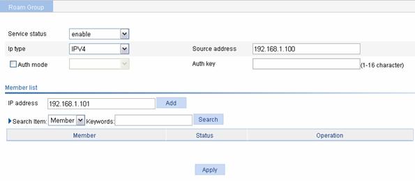
l Select enable from the Service Status drop-down list.
l Select IPV4, and type the source address.
l Type the IP address of AP 2 in the member list, and click Add.
l Click Apply.
Follow the above steps to configure a roaming group on AC 2. The source address is the IP address of AC 2, and the member address is the IP address of AC 1.
Configuration verification
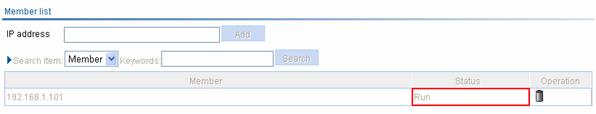
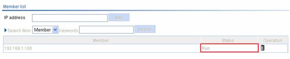
1) Verify that the roaming group is in the normal state.
On AC 1, you can see:
Figure 1-16 Check the roaming group state
On AC 2, you can see:
Figure 1-17 Check the roaming group state:
2) Method 1
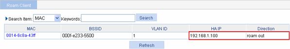
After the client roams from AP 1 to AP 2, select Roam > Roam Client on AC 1, and you can see that the client roams out of 192.168.1.100, as shown in Figure 1-18; select Roam > Roam Client on AC 2, and you can see that the client roams in to 192.168.1.100.
Figure 1-18 View client information
3) Method 2
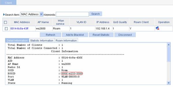
Before roaming, select Summary > Client, select the Detail Information tab, and then click the desired client to view the roaming information of the client.
From the roaming information, you can see that the client connects to the WLAN through AP 1, and the BSSID of AP 1 is 000f-e27b-3d90.
Figure 1-19 Client status before inter-AC roaming

After inter-AC roaming, you can see that the client is connected to the WLAN through AP 2, and the BSSID of AP 2 is 000f-e233-5500, as shown in Figure 1-20.
Figure 1-20 Client status after intra-AC roaming
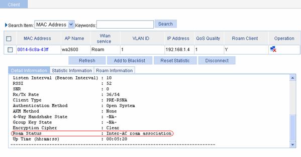
4) Method 3
Select Summary > Client, select the Detail Information tab, and then click the desired client. You will see that Intra-AC roam association is displayed in the Roam Status field, as shown in Figure 1-21.
Figure 1-21 Verify inter-AC roaming
Configuration guidelines
l The SSID of the two APs should be the same for inter-AC roaming, and the client should be connected to AP 1 and AP 2 using the same authentication mode.
l Configure a roaming group on both ACs.