- Table of Contents
-
- H3C WX Series Access Controllers Web-Based Configuration Manual-6PW103
- 00-1Cover
- 01-Quick Start
- 02-Web Overview
- 03-Summary
- 04-Device
- 05-Network
- 06-AP Configuration
- 07-WLAN Service Configuration
- 08-WLAN Roaming Configuration
- 09-Radio Configuration
- 10-Authentication
- 11-Security
- 12-QoS
- 13-SNMP
- 14-Advanced Settings
- Related Documents
-
| Title | Size | Download |
|---|---|---|
| 07-WLAN Service Configuration | 1.04 MB |
Table of Contents
1 Wireless Service Configuration
Configuring Clear Type Wireless Service
Configuring Crypto Type Wireless Service
Security Parameter Dependencies
Displaying Wireless Service Information·
Wireless Service Configuration Examples
Wireless Service Configuration Example
PSK Authentication Configuration Example
Local MAC Authentication Configuration Example
l The sample Web page information in this manual was created on the WX5002. The Web page information on your device may vary.
l The models listed in this manual are not applicable to all regions. Please consult the local agents for the models applicable to your region.
Wireless Local Area Networks (WLAN) have become very popular because they are very easy to setup and use, and have low maintenance costs. Generally, one or more access points (APs) can cover a building or an area. A WLAN is not completely wireless because the servers in the backbone are fixed.
The WLAN solution allows you to provide the following wireless LAN services to your customers:
l Connectivity to the Internet
l WLAN client connectivity to conventional 802.3 LANs
l Secured WLAN access with different authentication and encryption methods
l Seamless roaming of WLAN clients in the mobility domain
Access Service
Terminology
Client
A handheld computer or laptop with a wireless Network Interface Card (NIC) can be a WLAN client.
Access point (AP)
An AP bridges frames between wireless and wired networks.
Access controller (AC)
An AC can control and manage all APs in a WLAN. The AC communicates with an authentication server for WLAN client authentication.
Fat AP
A fat AP controls and manages all associated wireless stations and bridges frames between wired and wireless networks.
SSID
The service set identifier. A client scans all networks at first, and then selects a specific SSID to connect to a specific wireless network.
Wireless medium
A medium that is used for transmitting frames between wireless clients. Radio frequency is used as the wireless medium in the WLAN system.
Distribution system
A distribution system is used to forward frames to their destinations. It is the backbone to transmit frames between access points.
Split MAC
In split MAC mode, APs and ACs manage different services. An AP manages real-time services, such as beacon generation, power management, fragmentation and defragmentation. An AC manages services related to packet distribution, association, dissociation and reassociation.
Client Access
A client access process involves three steps: active/passive scanning, authentication and association.
Figure 1-1 Establish a client access

Scanning
1) Active scanning
Active scanning is used by clients to scan surrounding wireless networks and locate a compatible one. Active scanning falls into two modes according to whether a specified SSID is carried in a probe request.
l A client sends a probe request (with the SSID null): The client prepares a list of channels and broadcasts a probe request frame on each of them. APs that receive the probe request send a probe response. The client associates with the AP with the strongest signal. This active scanning mode enables a client to know whether an AP can provide wireless services.
Figure 1-2 Active scanning (the SSID of the probe request is null)
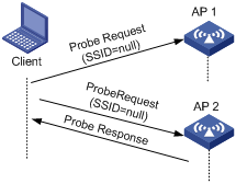
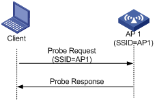
l A client sends a probe request (with a specified SSID): In this case, the client only unicasts a probe request because the probe request it sends carries the specified SSID. When an AP receives the probe request, it sends a probe response. This active scanning mode enables a client to access a specified wireless network.
Figure 1-3 Active scanning (the probe request carries the specified SSID)
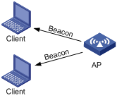
2) Passive scanning
Passive scanning is used by clients to discover surrounding wireless networks through listening to the beacon frames periodically sent by an AP. The client prepares a list of channels and listens to beacons on each of these channels. In this case, the AP needs to periodically broadcast beacon frames. Passive scanning is used by a client when it wants to save battery power. Typically, VoIP clients adopt the passive scanning mode.
Figure 1-4 Passive scanning
Authentication
To prevent unauthorized clients from accessing a network, authentication is needed between clients and ACs or between clients and fat APs. There are two types of authentication:
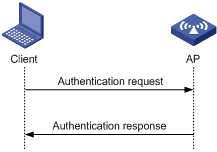
l Open system authentication
Open system authentication is the default authentication algorithm. This is the simplest of the available authentication algorithms. Essentially it is a null authentication algorithm. Any client that requests authentication with this algorithm can become authenticated. Open system authentication is not required to be successful as an AP may decline to authenticate the client. Open system authentication involves a two-step authentication process. The first step is to request for authentication. The second step is to return the authentication result. If the result is “successful,” the client and AP are mutually authenticated.
Figure 1-5 Open system authentication process
l Shared key authentication
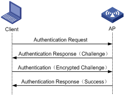
The following figure shows a shared key authentication process. The two parties have the same shared key configured.
2) The client sends an authentication request to the AP.
3) The AP randomly generates a challenge and sends it to the client.
4) The client uses the shared key to encrypt the challenge and sends it to the AP.
5) The AP uses the shared key to encrypt the challenge and compares the result with that received from the client. If they are identical, the client passes the authentication. If not, the authentication fails.
Figure 1-6 Shared key authentication process
Association
A client that wants to access a wireless network via an AP must be associated with that AP. Once the client chooses a compatible network with a specified SSID and authenticates to an AP, it sends an association request frame to the AP. The AP sends an association response to the client and adds the client’s information in its database. At a time, a client can associate with only one AP. An association process is always initiated by the client, but not by the AP.
Other related frames
1) De-authentication
An AC sends a de-authentication frame to remove a client from the wireless system. De-authentication can occur due to many reasons, such as:
l Receiving an association/disassociation frame from a client which is unauthenticated.
l Receiving a data frame from a client which is unauthenticated.
l Receiving a PS-poll frame from a client which is unauthenticated.
l The validity timer for a client expires and the port is not secured.
2) Dissociation
A client sends a dissociation frame to an AP to end the association between them. Dissociation can occur due to many reasons, such as:
l Receiving a data frame from a client which is authenticated and unassociated.
l Receiving a PS-Poll frame from a client which is authenticated and unassociated.
A dissociation frame is either unicast or broadcast.
3) Re-association
When a client is roaming from one AP to another AP, it sends a re-association request to the new AP. The AP relays this re-association request to the AC. The AC then informs the previous AP to delete the client’s information from its database, informs the new AP to add the client’s information in its database and conveys successful re-association information to the client.
When a client leaves the coverage of an AP, and then needs to re-join the AP, it must re-associate with the AP.
WLAN Data Security
Compared with wired networks, WLAN networks are more susceptible to attacks because all WLAN devices share the same medium and thus every device can receive data from any other sending device. If no security service is provided, plain-text data is transmitted over the WLAN.
To secure data transmission, 802.11 protocols provide some encryption methods to ensure that devices without the right key cannot read encrypted data.
1) WEP encryption
Wired Equivalent Privacy (WEP) was developed to protect data exchanged among authorized users in a wireless LAN from casual eavesdropping. WEP uses the RC4 algorithm to ensure data security and performs shared-key authentication, increasing protection against interception. Although WEP-104 enhances WEP encryption, it still has weaknesses due to limitations of RC4 encryption algorithm, too short IVs, and static key configuration.
WEP encryption can be used together with open-system authentication or shared key authentication.
l Open-system authentication: When this authentication mode is adopted, a WEP key is used for encryption only. Even if the configured key is not correct, a user can still get online. However, the data sent by the user will be discarded by the receiver due to the incorrect key.
l Shared-key authentication: When this authentication mode is adopted, a WEP key is used for both authentication and encryption. If the configured key is not correct, a user cannot pass authentication. That is, when WEP encryption is used together with the shared-key authentication mode, WEP can also be used as an authentication method.
2) TKIP encryption
Temporal Key Integrity Protocol (TKIP) is a cipher suite enhancing the WEP protocol on pre-RSNA hardware. It has many advantages over WEP. The main disadvantages of WEP include: it uses the same key for all frames though the IV changes, and it does not have a key management system.
TKIP solves these problems:
l First, TKIP provides longer IVs to enhance WEP security. Compared to WEP encryption, the key length in TKIP encryption increases from 40 bits to 128 bits, and the length of IVs increases from 24 bits to 48 bits.
l Second, TKIP allows for dynamic key negotiation to avoid static key configuration. TKIP replaces a single static key with a base key generated by an authentication server. Although TKIP uses the same RC4 algorithm as WEP, its dynamic keys cannot be easily attacked.
l Third, TKIP offers Message Integrity Check (MIC) and countermeasure functions. When the MIC is wrong, the data may be tampered, and the system may be attacked. In this case, countermeasures can be taken to prevent attacks.
3) CCMP encryption
CTR with CBC-MAC protocol (CCMP) is based on the CCM of the AES encryption algorithm. CCM combines CTR for confidentiality and CBC-MAC for authentication and integrity. CCM protects the integrity of both the MPDU Data field and selected portions of the IEEE 802.11 MPDU header. All AES processing used within CCMP uses AES with a 128-bit key and a 128-bit block size. CCM requires a fresh temporal key for every session. CCM also requires a unique nonce value for each frame protected by a given temporal key, and CCMP uses a 48-bit packet number (PN) for this purpose. Reuse of a PN with the same temporal key voids all security guarantees.
Client Access Authentication
1) PSK authentication
To implement PSK authentication, the client and the authenticator must have the same shared key configured. Otherwise, the client cannot pass pre-shared key (PSK) authentication.
2) 802.1x authentication
As a port-based access control protocol, 802.1x authenticates and controls accessing devices at the port level. A device connected to an 802.1x-enabled port of a WLAN access control device can access the resources on the WLAN only after passing authentication.
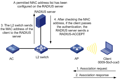
3) MAC authentication
MAC authentication provides a way for authenticating users based on ports and MAC addresses. You can configure permitted MAC address lists to filter MAC addresses of clients. However, the efficiency will be reduced when the number of clients increases. Therefore, MAC authentication is applicable to environments without high security requirements, for example, SOHO and small offices.
MAC authentication falls into two modes:
l Local MAC authentication: When this authentication mode is adopted, you need to configure a permitted MAC address list on the device. If the MAC address of a client is not in the list, its access request will be denied.
Figure 1-7 Local MAC authentication

l Remote Authentication Dial-In User Service (RADIUS) based MAC authentication: If the device finds that the current client is an unknown client, it sends an unsolicited authentication request to the RADIUS server. After the client passes the authentication, the client can access the WLAN network and the corresponding authorized information.
Figure 1-8 RADIUS-based MAC authentication
802.11n
As the next generation wireless LAN technology, 802.11n supports both 2.4GHz and 5GHz bands. It provides higher-speed services to customers by using the following two methods:
1) Increasing bandwidth: 802.11n can bond two adjacent 20-MHz channels together to form a 40-MHz channel. During data forwarding, the two 20-MHz channels can work separately with one acting as the primary channel and the other acting as the secondary channel or work together as a 40-MHz channel. This provides a simple way of doubling the data rate.
2) Improving channel utilization through the following ways:
l 802.11n introduces the A-MPDU frame format. By using only one PHY header, each A-MPDU can accommodate multiple Message Protocol Data Units (MPDUs) which have their PHY headers removed. This reduces the overhead in transmission and the number of ACK frames to be used, and thus improves network throughput.
l Similar with MPDU aggregation, multiple MAC Service Data Units (MSDU) can be aggregated into a single A-MSDU. This reduces the MAC header overhead and thus improves MAC layer forwarding efficiency.
l To improve physical layer performance, 802.11n introduces the short GI function, which shortens the GI interval of 800 us in 802.11a/g to 400 us. This can increase the data rate by 10 percent.
Configuring Access Service
Creating a Wireless Service
Select Wireless Service > Access Service from the navigation tree to enter the page for configuring access service, as shown in Figure 1-9:
Figure 1-9 Configure access service
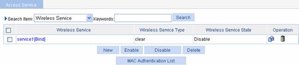
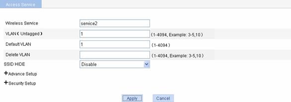
Click New to enter the page for creating a wireless service, as shown in Figure 1-10:
Figure 1-10 Create a wireless service
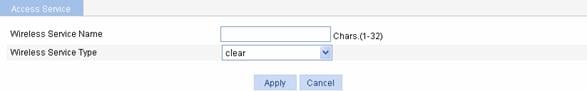
Table 1-1 shows the configuration items of creating a wireless service.
Table 1-1 Configuration items of creating a wireless service
|
Item |
Description |
|
Wireless Service Name |
Set the Service Set Identifier (SSID). An SSID should be as unique as possible. For security, the company name should not be contained in the SSID. Meanwhile, it is not recommended to use a long random string as the SSID, because a long random string only adds payload to the header field, without any improvement to wireless security. |
|
Wireless Service Type |
Select the wireless service type: l clear: Indicates the SSID will not be encrypted. l crypto: Indicates the SSID will be encrypted. |
Configuring Clear Type Wireless Service
Basic configuration of clear type wireless service
Select Wireless Service >
Access Service from the navigation tree, find the clear type wireless
service in the list, and click the corresponding ![]() icon to
enter the page for configuring wireless service, as shown in Figure 1-11.
icon to
enter the page for configuring wireless service, as shown in Figure 1-11.
![]()
To configure a clear type wireless service, you need to disable the
service first and then click the corresponding ![]() icon.
icon.
Figure 1-11 Configure clear type wireless service
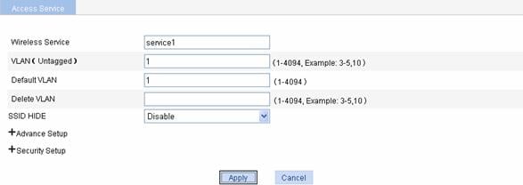
Table 1-2 shows the configuration items of basic configuration of clear type wireless service.
Table 1-2 Configuration items of basic configuration of clear type wireless service
|
Item |
Description |
|
Wireless Service Name |
Display the selected Service Set Identifier (SSID). |
|
VLAN (Untagged) |
Set the ID of the VLAN whose packets are to be sent untagged. VLAN (Untagged) indicates that the port sends the traffic of the VLAN with the VLAN tag removed. |
|
Default VLAN |
Set the default VLAN of a port. By default, the default VLAN of all ports is VLAN 1. You can configure the default VLAN as needed. |
|
Delete VLAN |
Remove the VLAN of a port. |
|
SSID HIDE |
Enable or disable SSID advertisement in beacon frames. By default, SSID is advertised in beacon frames. l Enable: Disables SSID advertisement in beacon frames. l Disable: Enables SSID advertisement in beacon frames.
l If SSID advertisement in beacon frames is disabled, the SSID must be configured for the clients to associate with the AP. l Disabling SSID advertisement in beacon frames does little good to wireless security. Allowing SSID advertisement in beacon frames enables an AP to discover a client more easily. |
Advanced configuration of clear type wireless service
Select Wireless Service >
Access Service from the navigation tree, find the clear type wireless
service in the list, click the corresponding ![]() icon, and click “+”
before Advance Setup to enter the page for configuring advanced settings
of clear type wireless service, as shown in Figure 1-12.
icon, and click “+”
before Advance Setup to enter the page for configuring advanced settings
of clear type wireless service, as shown in Figure 1-12.
Figure 1-12 Advanced configuration of clear type wireless service
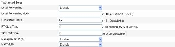
Table 1-3 shows the configuration items of advanced configuration of clear type wireless service.
Table 1-3 Configuration items of basic configuration of clear type wireless service
|
Item |
Description |
|
Local Forwarding |
Local forwarding enables an AP to forward data frames between clients. In a centralized WLAN architecture, an AP transparently transmits data frames to an AC for processing. With the increase of clients, the forwarding load of the AC increases either. With local forwarding enabled, an AP, rather than the AC, forwards client data, greatly reducing the load of the AC. l Enable: If local forwarding is enabled, data frames from an associated station will be forwarded by the AP itself. l Disable: If local forwarding is disabled, data frames from an associated station will be handled by the AC. |
|
Local Forwarding VLAN |
Clients using the same SSID may belong to different VLANs. You can configure a local forwarding VLAN when configuring a local forwarding policy based on VLANs. |
|
Client Max Users |
Specify the maximum number of associated clients of a SSID. If the number of associated clients of the SSID reaches the maximum, no clients can join the SSID until some associated clients disassociate for some reason. |
|
Management Right |
Web interface management right of online clients l Disable: Disables the web interface management right of online clients. l Enable: Enables the web interface management right of online clients. |
|
MAC VLAN |
You need to enable the MAC VLAN function before you can bind a VLAN ID to an AP radio. l Enable: Enables MAC VLAN for the wireless service. l Disable: Disables MAC VLAN for the wireless service. |
Security configuration of clear type wireless service
Select Wireless Service >
Access Service from the navigation tree, find the clear type wireless
service in the list, click the corresponding ![]() icon and click “+”
before Security Setup to enter the page shown in Figure 1-13:
icon and click “+”
before Security Setup to enter the page shown in Figure 1-13:
Figure 1-13 Security configuration of clear type wireless service

Table 1-4 shows the configuration items of security configuration of clear type wireless service.
Table 1-4 Configuration items of security configuration of clear type wireless service
|
Item |
Description |
|
|
Authentication Type |
For the clear type wireless service, you can select Open-System only. When you select the Open-System authentication mode, you cannot select the Encryption Mode check box. |
|
|
Port Security |
Port Mode |
l mac-authentication: Performs MAC address authentication on users. l mac-else-userlogin-secure: This mode is the combination of the mac-authentication and userlogin-secure modes, with MAC authentication having a higher priority. Upon receiving a non-802.1X frame, a port in this mode performs only MAC authentication; upon receiving an 802.1X frame, the port performs MAC authentication and then, if MAC authentication fails, 802.1X authentication. l mac-else-userlogin-secure-ext: This mode is similar to the mac-else-userlogin-secure mode, except that it supports multiple 802.1X and MAC authentication users on the port. l userlogin-secure: In this mode, port-based 802.1X authentication is performed for users; multiple 802.1X authenticated users can access the port, but only one user can be online. l userlogin-secure-or-mac: This mode is the combination of the userlogin-secure and mac-authentication modes, with 802.1X authentication having a higher priority. For a wireless user, 802.1X authentication is performed first. If 802.1X authentication fails, MAC authentication is performed. l userlogin-secure-or-mac-ext: This mode is similar to the userlogin-secure-or-mac mode, except that it supports multiple 802.1X and MAC authentication users on the port. l userlogin-secure-ext: In this mode, a port performs 802.1X authentication on users in macbased mode and supports multiple 802.1X users.
There are multiple security modes. To remember them easily, follow these rules to understand part of the port security mode names: l userLogin indicates port-based 802.1X authentication. l macAddress indicates MAC address authentication. l The authentication mode before Else is used preferentially. If the authentication fails, the authentication after Else may be used depending on the protocol type of the packets to be authenticated. l The authentication mode before Or and that after Or have the same priority. The device determines the authentication mode according to the protocol type of the packets to be authenticated. For wireless users, the 802.1X authentication mode is used preferentially. l userLogin together with Secure indicates MAC-based 802.1X authentication. l A security mode with Ext allows multiple 802.1X users to pass the authentication. A security mode without Ext allows only one 802.1X user to pass the authentication. |
|
Max User |
Specify the maximum number of users that can be connected to the network through a specific port. |
|
2) Configuring mac-authentication
Figure 1-14 mac-authentication port security configuration page
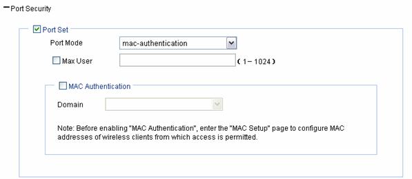
Table 1-5 shows the mac-authentication port security configuration items.
Table 1-5 mac-authentication port security configuration items
|
Item |
Description |
|
Port Mode |
mac-authentication: MAC-based authentication is performed on access users. |
|
Max User |
Control the maximum number of users allowed to access the network through the port. |
|
MAC Authentication |
Select the MAC Authentication check box. |
|
Domain |
Select an existing domain from the drop-down list. The default domain is system. To create a domain, select Authentication > AAA from the navigation tree, click the Domain Setup tab, and type a new domain name in the Domain Name combo box. |
3) Configuring userlogin-secure/userlogin-secure-ext
Figure 1-15 userlogin-secure/userlogin-secure-ext port security configuration page (userlogin-secure is taken for example)

Table 1-6 shows the userlogin-secure/userlogin-secure-ext port security configuration items.
Table 1-6 userlogin-secure/userlogin-secure-ext port security configuration items
|
Item |
Description |
|
Port Mode |
l userlogin-secure: Perform port-based 802.1X authentication for access users. In this mode, multiple 802.1X authenticated users can access the port, but only one user can be online. l userlogin-secure-ext: Perform MAC-based 802.1X authentication for access users. In this mode, the port supports multiple 802.1X users. |
|
Max User |
Control the maximum number of users allowed to access the network through the port. |
|
Mandatory Domain |
Select an existing domain from the drop-down list. After a mandatory domain is configured, all 802.1X users accessing the port are forced to use the mandatory domain for authentication, authorization, and accounting. The default domain is system. To create a domain, select Authentication > AAA from the navigation tree, click the Domain Setup tab, and type a new domain name in the Domain Name combo box. |
|
Authentication Method |
l EAP: Use the Extensible Authentication Protocol (EAP). With EAP authentication, the authenticator encapsulates 802.1X user information in the EAP attributes of RADIUS packets and sends the packets to the RADIUS server for authentication; it does not need to repackage the EAP packets into standard RADIUS packets for authentication. l CHAP: Use the Challenge Handshake Authentication Protocol (CHAP). By default, CHAP is used. CHAP transmits only user names rather than passwords over the network. Therefore this method is safer. l PAP: Use the Password Authentication Protocol (PAP). PAP transmits passwords in plain text. |
|
Handshake |
l Enable: Enable the online user handshake function so that the device can periodically send handshake messages to a user to check whether the user is online. By default, the function is enabled. l Disable: Disable the online user handshake function. |
|
Multicast Trigger |
l Enable: Enable the multicast trigger function of 802.1X to send multicast trigger messages to the clients periodically for initiating authentication. By default, the multicast trigger function is enabled. l Disable: Disable the 802.1X multicast trigger function.
For a WLAN, the clients can actively initiate authentication, or the AP can discover users and trigger authentication. Therefore, the ports do not need to send 802.1X multicast trigger messages for initiating authentication periodically. You are recommended to disable the multicast trigger function in a WLAN because the multicast trigger messages consume bandwidth. |
4) Configuring the other four port security modes
Figure 1-16 Port security configuration page for the other four security modes (mac-else-userlogin-secure is taken for example)
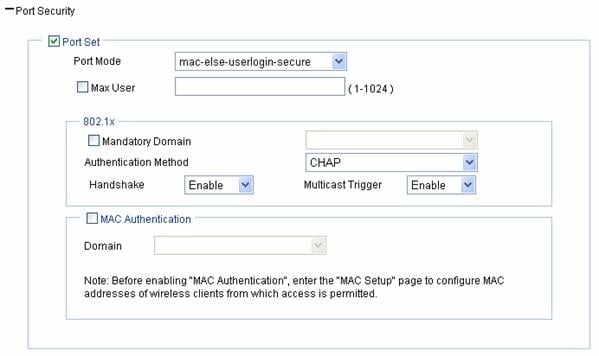
Table 1-7 shows the configuration items of the other four security modes.
Table 1-7 Configuration items of the other four security modes
|
Item |
Description |
|
Port Mode |
l mac-else-userlogin-secure: This mode is the combination of the mac-authentication and userlogin-secure modes, with MAC authentication having a higher priority. Upon receiving a non-802.1X frame, a port in this mode performs only MAC authentication; upon receiving an 802.1X frame, the port performs MAC authentication and then, if MAC authentication fails, 802.1X authentication. l mac-else-userlogin-secure-ext: This mode is similar to the mac-else-userlogin-secure mode, except that it supports multiple 802.1X and MAC authentication users on the port. l userlogin-secure-or-mac: This mode is the combination of the userlogin-secure and mac-authentication modes, with 802.1X authentication having a higher priority. For a wireless user, 802.1X authentication is performed first. If 802.1X authentication fails, MAC authentication is performed. l userlogin-secure-or-mac-ext: This mode is similar to the userlogin-secure-or-mac mode, except that it supports multiple 802.1X and MAC authentication users on the port. |
|
Max User |
Control the maximum number of users allowed to access the network through the port. |
|
Mandatory Domain |
Select an existing domain from the drop-down list. After a mandatory domain is configured, all 802.1X users accessing the port are forced to use the mandatory domain for authentication, authorization, and accounting. The default domain is system. To create a domain, select Authentication > AAA from the navigation tree, click the Domain Setup tab, and type a new domain name in the Domain Name combo box. |
|
Authentication Method |
l EAP: Use the Extensible Authentication Protocol (EAP). With EAP authentication, the authenticator encapsulates 802.1X user information in the EAP attributes of RADIUS packets and sends the packets to the RADIUS server for authentication; it does not need to repackage the EAP packets into standard RADIUS packets for authentication. l CHAP: Use the Challenge Handshake Authentication Protocol (CHAP). By default, CHAP is used. CHAP transmits only usernames but not passwords over the network. Therefore this method is safer. l PAP: Use the Password Authentication Protocol (PAP). PAP transmits passwords in plain text. |
|
Handshake |
l Enable: Enable the online user handshake function so that the device can periodically send handshake messages to a user to check whether the user is online. By default, the function is enabled. l Disable: Disable the online user handshake function. |
|
Multicast Trigger |
l Enable: Enable the multicast trigger function of 802.1X to send multicast trigger messages to the clients periodically for initiating authentication. By default, the multicast trigger function is enabled. l Disable: Disable the 802.1X multicast trigger function.
For a WLAN, the clients can actively initiate authentication, or the AP can discover users and trigger authentication. Therefore, the ports do not need to send 802.1X multicast trigger messages periodically for initiating authentication. You are recommended to disable the multicast trigger function in a WLAN because the multicast trigger messages consume bandwidth. |
|
MAC Authentication |
Select the MAC Authentication check box. |
|
Domain |
Select an existing domain from the drop-down list. The default domain is system. To create a domain, select Authentication > AAA from the navigation tree, click the Domain Setup tab, and type a new domain name in the Domain Name combo box. |
Configuring Crypto Type Wireless Service
Basic configuration of crypto type wireless service
Select Wireless Service >
Access Service from the navigation tree, find the crypto type wireless
service in the list, and click the corresponding ![]() icon to
enter the page shown in Figure
1-17:
icon to
enter the page shown in Figure
1-17:
Figure 1-17 Crypto type wireless service
See Table 1-2 for the configuration items of basic configuration of crypto type wireless service.
Advanced configuration of crypto type wireless service
Select Wireless Service >
Access Service from the navigation tree, find the crypto type wireless
service in the list, click the corresponding ![]() icon and click “+”
before Advance Setup to enter the page shown in Figure 1-18:
icon and click “+”
before Advance Setup to enter the page shown in Figure 1-18:
Figure 1-18 Advanced configuration of crypto type wireless service
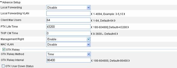
Table 1-8 shows the configuration items of advanced configuration of crypto type wireless service.
Table 1-8 Configuration items of advanced configuration of crypto type wireless service
|
Item |
Description |
|
Local Forwarding |
Local forwarding enables an AP to forward data frames between clients. In a centralized WLAN architecture, an AP transparently transmits data frames to an AC for processing. With the increase of clients, the forwarding load of the AC increases either. With local forwarding enabled, an AP, rather the AC, forwards client data, greatly reducing the load of the AC. l Enable: If local forwarding is enabled, data frames from an associated station will be forwarded by the AP itself. l Disable: If local forwarding is disabled, data frames from an associated station will be handled by the AC. |
|
Local Forwarding VLAN |
Clients using the same SSID may belong to different VLANs. You can configure a local forwarding VLAN when configuring a local forwarding policy. |
|
Client Max Users |
Maximum number of associated clients in a BSS. If the number of associated clients in the BSS reaches the maximum, no clients can join the BSS until some associated clients disassociate for some reason. |
|
PTK Life Time |
Set the pairwise transient key (PTK) lifetime. A PTK is generated through a four-way handshake. |
|
TKIP CM Time |
Set the TKIP countermeasure time. If more than two MIC failures occur within the specified time, the TKIP associations are disassociated and no new associations are allowed within next 60 seconds. |
|
Management Right |
Web interface management right of online clients l Disable: Disables the web interface management right of online clients. l Enable: Enables the web interface management right of online clients. |
|
MAC VLAN |
You need to enable the MAC VLAN function before you can bind a VLAN ID to an AP radio. l Enable: Enables MAC VLAN for the wireless service. l Disable: Disables MAC VLAN for the wireless service. |
|
GTK Rekey Method |
An AC generates a group transient key (GTK) and sends the GTK to a client during the authentication process between an AP and the client through group key handshake/the 4-way handshake. The client uses the GTK to decrypt broadcast and multicast packets. l If option Time is selected, the GTK will be refreshed after a configurable interval. The default interval is 86400 seconds. l If option Packet is selected, the GTK will be refreshed after a specified number of packets are transmitted. The default packet number is 10000000. |
|
GTK User Down Status |
Enable refreshing the GTK when some client goes offline, which is disabled by default. |
Security configuration of crypto type wireless service
Select Wireless Service >
Access Service from the navigation tree, find the crypto type wireless
service in the list, click the corresponding ![]() icon and click “+”
before Security Setup to enter the page shown in Figure 1-19.
icon and click “+”
before Security Setup to enter the page shown in Figure 1-19.
Figure 1-19 Security configuration of crypto type wireless service

Table 1-9 shows the configuration items of security configuration of crypto type wireless service.
Table 1-9 Configuration items of security configuration of crypto type wireless service
|
Item |
Description |
|
Authentication Type |
l Open-System: Namely, no authentication. With this authentication mode enabled, all the clients will pass the authentication. l Shared-Key: The two parties need to have the same shared key configured for this authentication mode. You can select this option only when WEP encryption mode is used. l Open-System and Shared-Key: It indicates that you can select both open-system and shared-key authentication. |
|
Cipher Suite |
l CCMP: CTR with CBC-MAC protocol (CCMP) is based on the CCM of the AES encryption algorithm and is only for RSNA stations. l TKIP: Temporal Key Integrity Protocol (TKIP) is a cipher suite enhancing the WEP protocol on pre-RSNA hardware. It has many advantages over WEP. l CCMP and TKIP: It indicates that you can select both CCMP and TKIP encryption. |
|
Security IE |
l WPA: Wi-Fi Protected Access l RSN: An RSN is a security network that allows only the creation of robust security network associations (RSNAs). It provides greater protection than WEP and WPA. l WPA and RSN: It indicates that you can select both WPA and RSN. |
|
Encryption |
|
|
WEP |
l wep40: Indicates the WEP40 key option. l wep104: Indicates the WEP104 key option. |
|
Key ID |
l 1: Key index 1. l 2: Key index 2. l 3: Key index 3. l 4: Key index 4. There are 4 static keys in WEP. The key index can be 1, 2, 3 or 4. The key corresponding to the specified key index will be used for encrypting and decrypting broadcast and multicast frames. |
|
Key Length |
Key length. l For wep40, the key is a string of 5 alphanumeric characters or a 10-digit hexadecimal number. l For wep104, the key is a string of 13 alphanumeric characters or a 26-digit hexadecimal number. |
|
WEP Key |
Configure the WEP key. |
|
Port Security |
See Table 1-4. Parameters such as the authentication type and cipher suite determine the port mode. Refer to Table 1-13 for details. After you select the Cipher Suite option, the following four port security modes are added: l userlogin-secure-ext-or-psk: The access user and the device interact to determine whether to perform MAC-based 802.1X authentication or PSK negotiation. l mac and psk: MAC-based authentication must be performed on access users first. If MAC-based authentication succeeds, an access user has to use the pre-configured PSK to negotiate with the device. Access to the port is allowed only after the negotiation succeeds. l psk: An access user must use the pre-shared key (PSK) that is pre-configured to negotiate with the device. The access to the port is allowed only after the negotiation succeeds. l userlogin-secure-ext: Perform MAC-based 802.1X authentication for access users. In this mode, the port supports multiple 802.1X users. |
2) Configuring userlogin-secure-ext-or-psk
Figure 1-20 userlogin-secure-ext-or-psk port security configuration page
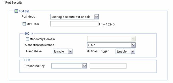
Table 1-10 shows the userlogin-secure-ext-or-psk port security configuration items.
Table 1-10 userlogin-secure-ext-or-psk port security configuration items
|
Item |
Description |
|
Port Mode |
userlogin-secure-ext-or-psk: The access user and the device interact to determine whether to perform MAC-based 802.1X authentication or PSK negotiation. |
|
Max User |
Control the maximum number of users allowed to access the network through the port. |
|
Mandatory Domain |
Select an existing domain from the drop-down list. After a mandatory domain is configured, all 802.1X users accessing the port are forced to use the mandatory domain for authentication, authorization, and accounting. The default domain is system. To create a domain, select Authentication > AAA from the navigation tree, click the Domain Setup tab, and type a new domain name in the Domain Name combo box. |
|
Authentication Method |
l EAP: Use the Extensible Authentication Protocol (EAP). With EAP authentication, the authenticator encapsulates 802.1X user information in the EAP attributes of RADIUS packets and sends the packets to the RADIUS server for authentication; it does not need to repackage the EAP packets into standard RADIUS packets for authentication. l CHAP: Use the Challenge Handshake Authentication Protocol (CHAP). By default, CHAP is used. CHAP transmits only usernames but not passwords over the network. Therefore this method is safer. l PAP: Use the Password Authentication Protocol (PAP). PAP transmits passwords in plain text. |
|
Handshake |
l Enable: Enable the online user handshake function so that the device can periodically send handshake messages to a user to check whether the user is online. By default, the function is enabled. l Disable: Disable the online user handshake function. |
|
Pre-shared Key |
l pass-phrase: Enter a PSK in the form of a character string. You should enter a string that can be displayed and is of 8 to 63 characters. l raw-key: Enter a PSK in the form of a hexadecimal number. You should input a valid 64-bit hexadecimal number. |
3) Configuring mac and psk
Figure 1-21 mac and psk port security configuration page
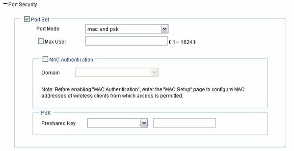
Table 1-11 shows the mac and psk port security configuration items.
Table 1-11 mac and psk port security configuration items
|
Item |
Description |
|
Port Mode |
mac and psk: MAC-based authentication must be performed on access users first. If MAC-based authentication succeeds, an access user has to use the pre-configured PSK to negotiate with the device. Access to the port is allowed only after the negotiation succeeds. |
|
Max User |
Control the maximum number of users allowed to access the network through the port. |
|
MAC Authentication |
Select the MAC Authentication check box. |
|
Domain |
Select an existing domain from the drop-down list. The default domain is system. To create a domain, select Authentication > AAA from the navigation tree, click the Domain Setup tab, and type a new domain name in the Domain Name combo box. |
|
Pre-shared Key |
l pass-phrase: Enter a PSK in the form of a character string. You should enter a string that can be displayed and is of 8 to 63 characters. l raw-key: Enter a PSK in the form of a hexadecimal number. You should input a valid 64-bit hexadecimal number. |
4) Configuring psk
Figure 1-22 psk port security configuration page
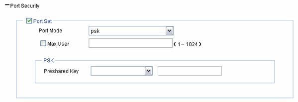
Table 1-12 shows the psk port security configuration items.
Table 1-12 psk port security configuration items
|
Item |
Description |
|
Port Mode |
psk: An access user must use the pre-shared key (PSK) that is pre-configured to negotiate with the device. The access to the port is allowed only after the negotiation succeeds. |
|
Max User |
Control the maximum number of users allowed to access the network through the port. |
|
Pre-shared Key |
l pass-phrase: Enter a PSK in the form of a character string. You should enter a string that can be displayed and is of 8 to 63 characters. l raw-key: Enter a PSK in the form of a hexadecimal number. You should input a valid 64-bit hexadecimal number. |
5) Configuring userlogin-secure-ext
Perform the configurations as shown in Configuring userlogin-secure/userlogin-secure-ext.
Security Parameter Dependencies
In a clear-type wireless service or crypto-type wireless service, the security parameter dependencies are as shown in Table 1-13.
Table 1-13 Security parameters
|
Service type |
Authentication type |
Cipher suite |
Security IE |
WEP/key ID |
Port mode |
|
Clear |
Open-System |
Unavailable |
Unavailable |
Unavailable |
mac-authentication mac-else-userlogin-secure mac-else-userlogin-secure-ext userlogin-secure userlogin-secure-ext userlogin-secure-or-mac userlogin-secure-or-mac-ext |
|
Crypto |
Open-System |
Selected |
Required |
It is optional to select WEP. The key ID can be 1, 2, 3, or 4 |
mac and psk psk userlogin-secure-ext-or-psk userlogin-secure-ext |
|
Unselected |
Unavailable |
It is required to select WEP. The key ID can be 1, 2, 3 or 4 |
mac-authentication |
||
|
Shared-Key |
Unavailable |
Unavailable |
It is required to select WEP. The key ID can be 1, 2, 3 or 4. |
mac-authentication |
|
|
Open-System and Shared-Key |
Selected |
Required |
WEP is optional. The key ID can be 1, 2, 3 or 4. |
mac and psk psk userlogin-secure-ext-or-psk userlogin-secure-ext |
|
|
Unselected |
Unavailable |
It is required to select WEP. The key ID can be 1, 2, 3 or 4 |
mac-authentication |
Binding an AP Radio
Binding an AP radio to a wireless service
Select Wireless Service > Access Service from the navigation tree, click Bind at the right side of the target wireless service in the wireless service list to enter the page shown in Figure 1-23:
Figure 1-23 Bind an AP radio to a wireless service
Select the AP to be bound, input the VLAN ID to be bound in the Binding VLAN text box and click Bind.
Binding an AP radio to a VLAN
Traffic of different services is identified by SSIDs. Locations are identified by APs. Users at different locations access different services. For a user roaming between different APs, you can provide services for the user based on its access AP. The detailed requirements are as follows:
l Users with the same SSID but accessing through different APs can be assigned to the same VLAN or different VLANs based on their configurations.
l After you configure VLANs for radios on different APs, VLANs that do not exist will be dynamically created. To make VLANs configured for the AP radios take effect, do not delete these VLANs.
l A roaming user always belongs to the same VLAN.
l For a user roaming between ACs, if the current AC does not have the output VLAN-interface, the user needs to use an HA in the AC group for forwarding packets to avoid packet loss.
Figure 1-24 Schematic diagram for AP-based access VLAN recognition

As shown in Figure 1-24, Client 1 goes online through AP 1 and belongs to VLAN 3. When Client 1 roams within an AC or between ACs, Client 1 always belongs to VLAN 3. When Client 1 roams between ACs, if FA, that is, AC 2, has VLAN-interface 3, AC 2 forwards packets from Client 1. Otherwise, packets from Client 1 are sent to HA (AC 1) through the data tunnel and then HA forwards these packets.
Client 2 goes online through AP 4 and belongs to VLAN 2. That is, a client going online through a different AP is assigned to a different VLAN.
Select Wireless Service >
Access Service from the navigation tree, find the wireless service to be
bound in the list, and click the corresponding ![]() icon to
enter the page shown in Figure
1-23.
icon to
enter the page shown in Figure
1-23.
Select the checkbox before the target AP, and input the VLAN to be bound in the text box after Binding VLAN, and click Bind.
Displaying Wireless Service Information
Displaying clear type wireless service information
Select Wireless Service > Access Service from the navigation tree, and click the target clear-type wireless service to enter the page shown in Figure 1-25.
Figure 1-25 Clear-type wireless service information
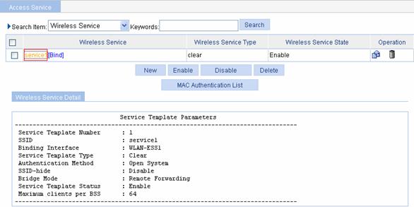
Table 1-14 Description of the clear-type wireless service information page
|
Item |
Description |
|
Service Template Number |
Wireless service template number |
|
SSID |
Service Set Identifier |
|
Binding Interface |
WLAN-ESS interface bound to the service template |
|
Service Template Type |
Service template type |
|
Authentication Method |
Authentication method. A clear-type wireless service can only use open system authentication. |
|
SSID-hide |
l Disable: Enables SSID advertisement. l Enable: Disables SSID advertisement. |
|
Bridge Mode |
l Local Forwarding: The local AP is enabled to forward packets. l Remote Forwarding: All packets are forwarded by the AC. |
|
Service Template Status |
l Enable: The wireless service is enabled. l Disable: The wireless service is disabled. |
|
Maximum clients per BSS |
Maximum number of clients a BSS can support. |
Displaying crypto type wireless service information
Select Wireless Service > Access Service from the navigation tree, and click the target crypto-type wireless service to enter the page shown in Figure 1-26.
Figure 1-26 Crypto-type wireless service information

Table 1-15 Description of the crypto-type wireless service information page
|
Item |
Description |
|
Service Template Number |
Wireless service template number |
|
SSID |
Service Set Identifier |
|
Binding Interface |
WLAN-ESS interface bound to the service template |
|
Service Template Type |
Service template type |
|
Security IE |
Security IE: WPA or RSN |
|
Authentication Method |
Authentication method: open system or shared key authentication. |
|
SSID-hide |
l Disable: Enables SSID advertisement. l Enable: Disables SSID advertisement. |
|
Cipher Suite |
CCMP, TKIP, WEP40 or WEP104 |
|
WEP Key Index |
WEP Key Index |
|
WEP Key Mode |
WEP key mode |
|
WEP Key |
WEP key |
|
TKIP Countermeasure Time(s) |
TKIP countermeasure time in seconds |
|
PTK Life Time(s) |
PTK life time in seconds |
|
GTK Rekey |
GTK rekey status |
|
GTK Rekey Method |
GTK rekey method: packet based or time based |
|
GTK Rekey Time(s) |
If GTK rekey is time based, the time interval (in seconds) is displayed. If GTK rekey is packet based, the number of packets is displayed. |
|
Bridge Mode |
l Local Forwarding: The local AP is enabled to forward packets. l Remote Forwarding: All packets are forwarded by the AC. |
|
Service Template Status |
l Enable: The wireless service is enabled. l Disable: The wireless service is disabled. |
|
Maximum clients per BSS |
Maximum number of clients a BSS can support. |
Wireless Service Configuration Examples
Wireless Service Configuration Example
Network requirement
As shown in Figure 1-27, an AC and an AP (serial ID 210235A29G007C000020) is connected through a Layer 2 switch.
It is required to:
l Manually type in the serial ID.
l Adopt dot11g radio mode.
l Adopt simple text authentication.
Figure 1-27 Wireless service configuration

Configuration procedure
1) Configure the AP
# Create an AP.
Select AP > AP Setup from the navigation tree, and click New to enter the page for creating an AP, as shown in Figure 1-28:
l Set the AP name to wa2200.
l Select the AP model WA2220-AG.
l Select the serial ID as manual, and type the serial ID of the AP.
l Click Apply.
2) Configure wireless service
# Create a wireless service.
Select Wireless Service > Access Service from the navigation tree, and click New to enter the page for creating a wireless service, as shown in Figure 1-29:
Figure 1-29 Create a wireless service
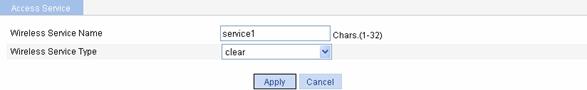
l Set the service name to service1.
l Select the wireless service type clear.
l Click Apply to enter the basic wireless service configuration page, and then click Apply.
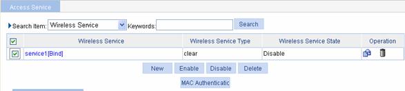
# Enable the wireless service.
Select Wireless Service > Access Service from the navigation tree to enter the page shown in Figure 1-30:
Figure 1-30 Enable wireless service
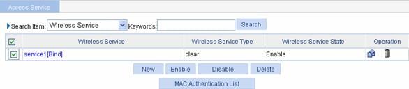
l Set the service1 check box.
l Click Enable.
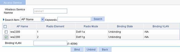
3) Bind an AP radio to a wireless service
Select Wireless Service > Access Service from the navigation tree, and click Bind at the right side of the wireless service service1 to enter the page for binding an AP radio, as shown in Figure 1-31:
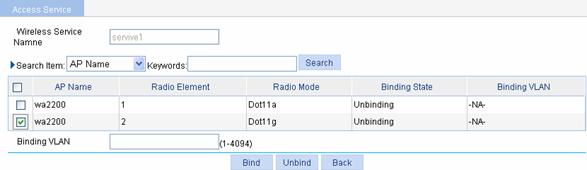
l Select the check box before wa2200 with radio type being Dot11g.
l Input the VLAN ID to be bound in the Binding VLAN text box.
l Click Bind.
4) Enable dot11g radio.
Select Radio > Radio Setup from the navigation tree to enter the radio setup page, as shown in Figure 1-32:
Figure 1-32 Enable dot11g radio
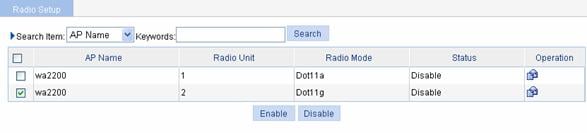
l Select the check box before wa2200 with the radio mode being Dot11g.
l Click Enable.
Configuration verficaion
1) Select Summary > Client from the navigation tree to enter the page as shown in Figure 1-33 to view the online clients.
Figure 1-33 View the online clients
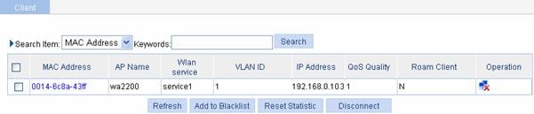
![]()
For an AC to get the IP address of a client, enable ARP snooping in system view. By default, ARP snooping is disabled, and IP address 0.0.0.0 is displayed in the IP Address column.
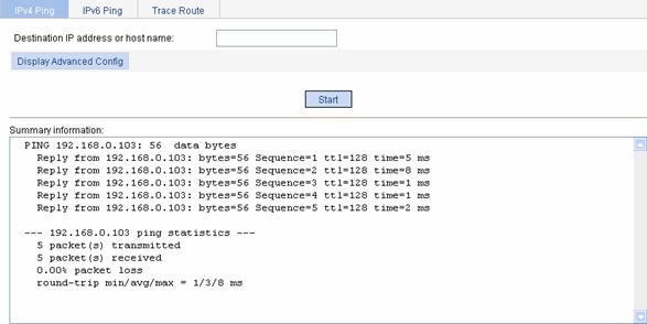
2) Select Network > Diagnostic Tools from the navigation tree, type in the client IP address 192.168.0.103, and click Start. Then you can see the brief information as shown in Figure 1-34, which indicates that the client has gone line.
Figure 1-34 Brief information for pinging a client
Configuration guidelines
Note the following when configuring a wireless service:
l Select a correct district code.
l Remove the binding between the wireless service and the AP before deleting a wireless service.
l Remove the binding between the wireless service and the AP before deleting the AP.
l If an AP cannot be in the run state, verify that the AP’s radio is bound and enabled.
Auto AP Configuration Example
Network requirement
As shown in Figure 1-35, an AC is connected to an AP through a Layer 2 switch.
It is required to:
l Use the auto AP function.
l Adopt dot11g radio mode.
l Adopt simple text authentication.
Figure 1-35 Diagram for auto AP configuration
Configuration procedure
1) Configure AP
# Create an AP.
Select AP > AP Setup from the navigation tree, and click New to enter the page for creating an AP, as shown in Figure 1-36:

l Set the AP name to wa2200.
l Select the AP model WA2220-AG.
l Select the serial ID as auto.
l Click Apply.
2) Configure wireless service
# Create a wireless service.
Select Wireless Service > Access Service from the navigation tree, and click New to enter the page for creating a wireless service, as shown in Figure 1-37:
Figure 1-37 Create a wireless service
l Set the service name to service1.
l Select the wireless service type clear.
l Click Apply to enter the basic wireless service configuration page, and then click Apply.
# Enable wireless service.
Select Wireless Service > Access Service from the navigation tree to enter the page for enabling wireless service, as shown in Figure 1-38:
Figure 1-38 Enable wireless service
l Select the service1 check box.
l Click Enable.
3) Bind an AP radio to a wireless service
Select Wireless Service > Access Service from the navigation tree, and click Bind at the right side of the wireless service service1 to enter the page for binding an AP radio, as shown in Figure 1-39:
l Select the check box before wa2200 with radio mode Dot11g.
l Input the VLAN ID to be bound in the Binding VLAN text box.
l Click Bind.
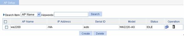
Select AP > AP Setup from the navigation tree to the view the AP status.
Figure 1-40 AP status before auto AP is enabled
4) Enable auto AP
Select AP > Auto AP from the navigation tree to enter the page for configuring auto AP, as shown in Figure 1-41:

l Select enable.
l Click Apply.
After enabling auto AP, you can view the automatically found AP (wa2200_001) by clicking Refresh.
Figure 1-42 View the automatically found AP

5) Switch to fat AP
l If you do not need to modify the automatically found AP name, you can select the wa2200_001 check box, and then click Transmit All AP.
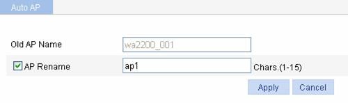
l
To modify the automatically found AP name, click
the ![]() icon in the
Operation column to modify the AP name, and then click Apply, as
shown in Figure 1-43:
icon in the
Operation column to modify the AP name, and then click Apply, as
shown in Figure 1-43:
Figure 1-43 Modify the AP name
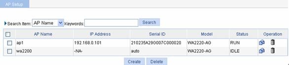
Select AP > AP Setup from the navigation tree, and you can view the AP with the name modified.
Figure 1-44 Display AP
6) Enable dot11g radio
Select Radio > Radio Setup from the navigation tree, find the AP with the corresponding radio mode and select the check box before the AP, and then click Enable.
Figure 1-45 Enable dot11g radio

Configuration verfication
l Select Summary > Client from the navigation tree to enter the page as shown in Figure 1-46 to view the online clients.
Figure 1-46 View the online clients

![]()
For an AC to get the IP address of a client, enable ARP snooping in system view. By default, ARP snooping is disabled, and IP address 0.0.0.0 is displayed in the IP Address column.
l The client can be pinged successfully on the AC.
Configuration guidelines
Note the following when configuring an AP:
l Select a correct district code.
l Remove the binding between the wireless service and the AP before deleting a wireless service.
l Remove the binding between the wireless service and the AP before deleting an AP.
l Select the AP (AP 1 in the example) with working mode having been switched when enabling the AP radio, rather than the AP in the auto AP template (wa2200 in the example).
l If you enable the radio of the AP in an auto AP template first, radios of all the automatically found APs are enabled.
802.11n Configuration Example
Network requirement
As shown in Figure 1-47, an AC is connected to an L2 switch. Configure the AP to support 802.11n.
Figure 1-47 802.11n network diagram
Configuration procedure
# Create an AP.
Select AP > AP Setup from the navigation tree, and click New to enter the page for creating an AP.
l Set the AP name to 11nap.
l Select the AP model WA2610E-AGN.
l Select the serial ID as manual, and type in the serial ID of the AP.
l Click Apply.
# Create a wireless service.
Select Wireless Service > Access Service from the navigation tree, and click New to enter the page for creating a wireless service.
l Set the service name to 11nservice.
l Select the wireless service type clear.
l Click Apply to enter the basic wireless service configuration page, and click Apply.
# Enable the wireless service.
Select Wireless Service > Access Service from the navigation tree to enter the page for enabling wireless service.
l Set the 11nservice check box.
l Click Enable.
# Bind an AP radio.
Select Wireless Service > Access Service from the navigation tree, and click Bind to enter the page for binding an AP radio.
l Select the 11nap check box.
l Click Bind.
# Enable dot11g radio.
Select Radio > Radio Setup from the navigation tree to enter the page for enabling dot11gn radio, find the AP with the corresponding radio mode and select the 11nap check box before it, and then click Enable.
Configuration verification
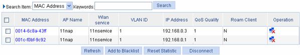
Select Summary > Client from the navigation tree to enter the page as shown in Figure 1-48 to view the online clients.
Figure 1-48 View the online clients
![]()
For an AC to get the IP address of a client, enable ARP snooping in system view. By default, ARP snooping is disabled, and IP address 0.0.0.0 is displayed in the IP Address column.
The client 0014-6c8a-43ff runs 802.11g and the client 001c-f0bf-9c92 runs 802.11n. Both of them are allowed to access the WLAN in this example. If only 802.11n clients are allowed, only client 001c-f0bf-9c92 can access the WLAN.
Configuration guidelines
Note the following when configuring 802.11n:
l Disable the radio before modifying 802.11n and rate settings.
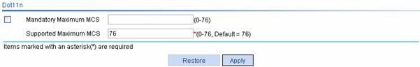
l Select Radio > Radio Setup from the navigation tree, select the AP to be configured, and click Apply to enter the page for configuring a radio, as shown in Figure 1-49. Then you can modify the 802.11n parameters, including bandwidth mode, A-MSDU, A-MSDU, short GI and whether non-11n clients are allowed.
Figure 1-49 Modify 802.11n parameters

l Select Radio > Rate from the navigation tree to set Dot11n rates, as shown in Figure 1-50.
PSK Authentication Configuration Example
Network requirements
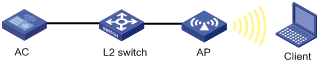
As shown in Figure 1-51, an AC is connected to an AP through a Layer 2 switch. AP and AC are in the same network segment. The PSK key on the client is the same as that on the AC, that is, 12345678.
Figure 1-51 Diagram for PSK authentication
Configuration procedure
1) Configure the AP
# Create an AP.
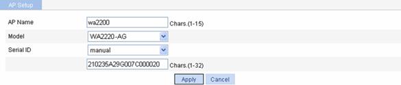
Select AP > AP Setup from the navigation tree, and click New to enter the page for creating an AP, as shown in Figure 1-52:

l Set the AP name to wa2200.
l Select the AP model WA2220-AG.
l Select the serial ID as manual, and type the AP serial ID.
l Click Apply.
2) Configure wireless service
# Create a wireless service.
Select Wireless Service > Access Service from the navigation tree, and click New to enter the page for creating a wireless service, as shown in Figure 1-53:
Figure 1-53 Create a wireless service

l Set the service name to psk.
l Select the wireless service type crypto.
l Click Apply.
# Configure the wireless service.
After you create a wireless service, you will enter the wireless service configuration page. You need to perform advanced setup and security setup when configuring PSK authentication, as shown in the following two figures:
Figure 1-54 Advanced setup


Advanced setup:
l Select Enable from the MAC VLAN drop-down list.
Security setup:
l Select Open-System from the Authentication Type drop-down list.
l Select Cipher Suite check box, select CCMP and TKIP (select an encryption type as needed), and then select WPA from the Security IE drop-down list.
l Select the Port Set check box, and select psk from the Port Mode drop-down list.
l Select pass-phrase from the Preshared Key drop-down list, and type key ID 12345678.
l Click Apply.
# Enable the wireless service.
Select Wireless Service > Access Service from the navigation tree to enter the page for enabling wireless service, as shown in Figure 1-56:
Figure 1-56 Enable wireless service
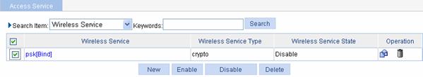
l Select the psk[Bind] check box.
l Click Enable.
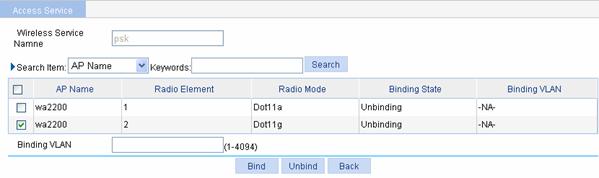
3) Bind an AP radio to a wireless service
Select Wireless Service > Access Service from the navigation tree, and click Bind at the right side of the wireless service service1 to enter the page for binding an AP radio, as shown in Figure 1-57:

l Select the check box before wa2200 with radio mode Dot11g.
l Input the VLAN ID to be bound in the Binding VLAN text box.
l Click Bind.
4) Enable dot11g radio
Select Radio > Radio Setup from the navigation tree to enter the page shown in Figure 1-58.
Figure 1-58 Enable dot11g radio

l Select the AP with the corresponding radio mode.
l Click Enable.
Configuration verfication
l The same PSK pre-shared key is configured on the client. The client can successfully associate with the AP and can access the WLAN network.
l The client can be pinged successfully on the AC.
Local MAC Authentication Configuration Example
Network requirements
AC is connected to AP through a Layer 2 switch, and they are in the same network. It is required to perform local MAC authentication on the client.
Figure 1-59 Diagram for local MAC authentication
Configuration procedure
1) Configure the AP
# Create an AP.
Select AP > AP Setup from the navigation tree, and click New to enter the page for creating an AP, as shown in Figure 1-60:
l Set the AP name to wa2200.
l Select the AP model WA2220-AG.
l Select the serial ID as manual, and type the AP serial ID.
l Click Apply.
2) Configure the wireless service
# Create a wireless service.
Select Wireless Service > Access Service from the navigation tree, and click New to enter the page for creating a wireless service, as shown in Figure 1-61:
Figure 1-61 Create a wireless service

l Set the service name to mac-auth.
l Select the wireless service type clear.
l Click Apply.
# Configure the wireless service.
After you create a wireless service, you will enter the wireless service configuration page. You need to perform advanced setup and security setup when configuring local MAC authentication, as shown in the following two figures:
Figure 1-62 Advanced setup

Advanced setup:
l Select Enable from the MAC VLAN drop-down list.
Security setup:
l Select Open-System from the Authentication Type drop-down list.
l Select the Port Set check box, and select mac-authentication from the Port Mode drop-down list.
l Select MAC Authentication check box, and select system from the Domain drop-down list (you can select Authentication > AAA from the navigation tree, click the Domain tab, and create a domain in the Domain drop-down combo box).
l Click Apply.
# Enable the wireless service.
Select Wireless Service > Access Service from the navigation tree to enter the page for enabling wireless service, as shown in Figure 1-64:
Figure 1-64 Enable wireless service
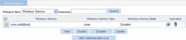
l Select the mac-auth check box.
l Click Enable.
3) Configure a MAC authentication list
Select Wireless Service > Access Service from the navigation tree, and click MAC Authentication List to enter the page for configuring a MAC authentication list, as shown in Figure 1-65:
Figure 1-65 Add a MAC authentication list

l Add a local user in the MAC Address box. 00-14-6c-8a-43-ff is added in this example.
l Click Add.
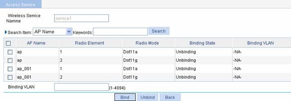
4) Bind an AP radio to a wireless service
Select Wireless Service > Access Service from the navigation tree, and click Bind at the right side of the wireless service mac-auth to enter the page for binding an AP radio, as shown in Figure 1-66:
l Select the check box before wa2200 with radio mode Dot11g.
l Click Bind.
5) Enable dot11g radio
Select Radio > Radio Setup from the navigation tree to enter the radio setup page, as shown in Figure 1-67.
Figure 1-67 Enable dot11g radio

l Find the AP with the corresponding radio mode and select the check box before wa2200 with radio mode Dot11g.
l Click Enable
6) Configure the wireless client
Launch the wireless client, refresh the network list, find the configured wireless service (mac-auth in this example), and click connect. If the client’s MAC address is in the MAC address authentication list, it can pass authentication and access the WLAN.
Configuration verification
l If the MAC address of the client is in the MAC authentication list, the client can pass authentication and access the WLAN network.
l The client can be pinged on the AC.