- Table of Contents
-
- H3C WX Series Access Controllers Web-Based Configuration Manual-6PW103
- 00-1Cover
- 01-Quick Start
- 02-Web Overview
- 03-Summary
- 04-Device
- 05-Network
- 06-AP Configuration
- 07-WLAN Service Configuration
- 08-WLAN Roaming Configuration
- 09-Radio Configuration
- 10-Authentication
- 11-Security
- 12-QoS
- 13-SNMP
- 14-Advanced Settings
- Related Documents
-
| Title | Size | Download |
|---|---|---|
| 03-Summary | 415.93 KB |
Table of Contents
l The sample Web page information in this manual was created on the WX5002. The Web page information on your device may vary.
l The models listed in this manual are not applicable to all regions. Please consult the local agents for the models applicable to your region.
Device Information Overview
You can view the following information on the Summary module:
l Device information
l System resource state
l Device interface information
l Recent system operation logs
After logging in to the Web interface, you will enter the Summary > Device page, as shown in Figure 1-1.
Figure 1-1 Device info page
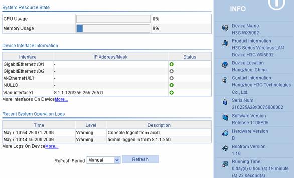
Select the refresh mode in the Refresh Period drop-down box.
l If you select a specific period, the system periodically refreshes the Device Info page;
l If you select Manual, you need to click Refresh to refresh the page.
Device Info
Table 1-1 describes the device information configuration items.
Table 1-1 Device information configuration items
|
Item |
Description |
|
Device Name |
Displays the device name. |
|
Product Information |
Displays the product information. |
|
Device Location |
Displays the location of the device. |
|
Contact Information |
Displays the contact information for device maintenance. |
|
SerialNum |
Displays the serial number of the device. |
|
Software Version |
Displays the software version of the device. |
|
Hardware Version |
Displays the hardware version of the device. |
|
Bootrom Version |
Displays the Boot ROM version of the device. |
|
Running Time |
Displays the running time after the latest boot of the device. |
System Resource State
Table 1-2 describes the system resource state configuration items.
Table 1-2 System resource state configuration items
|
Item |
Description |
|
CPU Usage |
Displays the real-time CPU usage. |
|
Memory Usage |
Displays the real-time memory usage. |
Device Interface Information
Table 1-3 describes the device interface information configuration items.
Table 1-3 Device interface information configuration items
|
Item |
Description |
|
Interface |
Displays interface name and interface number. |
|
IP Address/Mask |
Displays the IP address and mask of an interface. |
|
Status |
Displays interface status. l l l |
![]()
To know more information about device interfaces, click the More hyperlink under the Device Interface Information area to enter the Device > Interface page to view and operate the interfaces. For detailed information, refer to Interface Management Configuration in Device.
Recent System Operation Logs
Table 1-4 describes the recent system operation log configuration items.
Table 1-4 Recent system operation log configuration items
|
Item |
Note: |
|
Time |
Displays the time when the system operation logs are generated. |
|
Level |
Displays the level of the system operation logs. |
|
Description |
Displays the contents of the system operation logs. |
![]()
l The device info page only displays at most five recent login and logout logs in all system operation logs.
l To know more information about system operation logs, click the More hyperlink under the Recent System Operation Logs area to enter the Device > Syslog > Loglist page to view the logs. For detailed information, refer to Log Management Configuration in Device.
Displaying WLAN Service
Select Summary > WLAN Service from the navigation tree at the left side of the interface to enter the WLAN service page, as shown in Figure 1-2. Refer to Table 1-5 for detailed description of the fields of WLAN service information.
Figure 1-2 Display WLAN Service
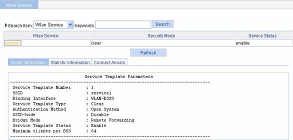
Table 1-5 describes the fields in the Detail Information area.
Table 1-5 Fields in the detailed information of the wireless service
|
Field |
Description |
|
Service Template Number |
Current service template number |
|
SSID |
Service set identifier (SSID) for the ESS |
|
Binding Interface |
Name of the interface bound with the service template |
|
Service Template Type |
Service template type: crypto, clear or wapi |
|
Security IE |
Security IE: WPA or RSN |
|
Authentication Method |
Authentication method: open system or shared key |
|
SSID-hide |
Enable or disable |
|
Bridge Mode |
Forwarding mode: l Local Forwarding l Remote Forwarding |
|
Cipher Suite |
Cipher suite: CCMP, TKIP, WEP40, or WEP104 |
|
TKIP Countermeasure Time(s) |
TKIP countermeasure time in seconds |
|
PTK Life Time(s) |
PTK lifetime in seconds |
|
GTK Rekey |
GTK rekey configured |
|
GTK Rekey Method |
GTK rekey method configured: packet based or time based |
|
GTK Rekey Time(s) |
Time for GTK rekey in seconds l If Time is selected, the GTK will be refreshed after a specified period of time. l If Packet is selected, the GTK will be refreshed after a specified number of packets are transmitted. |
|
Service Template Status |
Status: enabled or disabled |
|
Maximum clients per BSS |
Maximum number of associated clients per BSS |
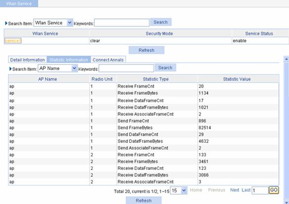
Statistics of the WLAN service are as shown in Figure 1-3.
Figure 1-3 Display WLAN service statistics
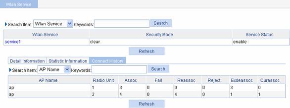
The connection history information of the WLAN service is as shown in Figure 1-4.
Figure 1-4 Display the connection history information of the WLAN service
Displaying AP
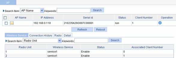
Select Summary > AP from the navigation tree to enter the AP page, as shown in Figure 1-5. You can display the WLAN service information of an AP by clicking the tabs on the page.
The WLAN service information of an AP is as shown in Figure 1-5.
Figure 1-5 Display wireless service
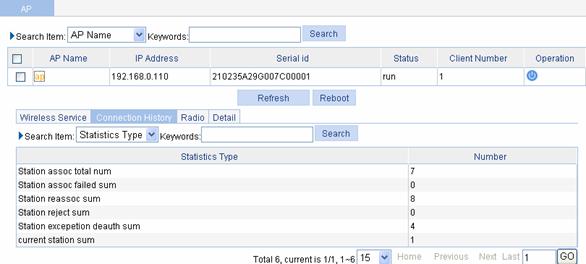
The connection history information of an AP is as shown in Figure 1-6.
Figure 1-6 Display AP connection history information
The radio statistics of an AP are as shown in Figure 1-7. For the description of the fields in the AP radio statistics, refer to Table 1-7.
Figure 1-7 Display AP radio statistics
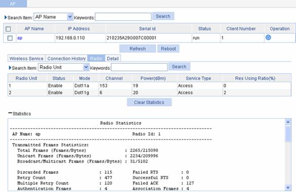
Table 1-6 Description on the fields of the AP radio statistics
|
Field |
Description |
|
AP Name |
Access point name |
|
Radio Id |
Radio ID |
|
Transmitted Frames Statistics |
Statistics of transmitted frames |
|
Total Frames |
Number of frames transmitted |
|
Unicast Frames |
Number of unicast frames transmitted |
|
Broadcast/Multicast Frames |
Number of broadcast or multicast frames transmitted |
|
Discarded Frames |
Number of frames discarded. |
|
Retry Count |
Number of transmission retries |
|
Multiple Retry Count |
Number of frames that have been retransmitted |
|
Authentication Frames |
Number of authentication request frames transmitted |
|
Failed RTS |
Number of RTS frames failed to be transmitted |
|
Successful RTS |
Number of RTS transmitted successfully |
|
Failed ACK |
Number of transmitted frames for which no acknowledgement is received |
|
Association Frames |
Number of association responses transmitted |
|
Received Frames Statistics |
Statistics of received frames |
|
Total Frames |
Number of frames received |
|
Unicast Frames |
Number of unicast frames received |
|
Broadcast/Multicast Frames |
Number of broadcast or multicast frames received |
|
Fragmented Frames |
Number of fragmented frames received |
|
FCS Failures |
Number of frames dropped due to FCS failure |
|
Authentication Frames |
Number of authentication response frames received |
|
Duplicate Frames |
Number of duplicate frames received |
|
Decryption Errors |
Number of frames dropped due to decryption error |
|
Association Frames |
Number of association requests received |
The detailed information of an AP is as shown in Figure 1-8. For the description of the fields in the AP detailed information, refer to Table 1-7.
Figure 1-8 Display AP detailed information
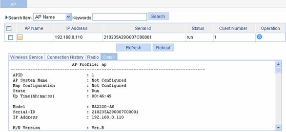
Table 1-7 Description on the fields of the AP information
|
Field |
Description |
|
APID |
Access point identifier |
|
Map Configuration |
Configuration file mapped to the AP |
|
AP System Name |
Access point name |
|
State |
Current state of the AP: l ImageDownload: The AP is downloading the version. If this field is always ImageDownload, check the following: 1) The version of the fit AP saved on the AC matches with the version that the AC requires; 2) The space of the flash is enough. l Idle: The AP is idle. If this field is always Idle, check the following: 1) If the fields of Latest Join IP Address and Tunnel Down Reason are displayed as -NA-, it indicates that the AP has never connected to the AC successfully. You need to check the network cable and power supply of the fit AP. 2) If the fields of Latest Join IP Address and Tunnel Down Reason are displayed as other contents, it indicates that the AP was once connected to the AC successfully. Refer to the output of the Tunnel Down Reason field for the detailed reason. l Run: The AP is operating. It indicates that the AP has connected to the AC successfully. Config: The AC is delivering configuration file to the fit AP, and the fit AP is reporting the radio information to the AC through the radio interface. This state is an instantaneous state. |
|
Up Time(hh:mm:ss) |
Time duration for which the AP has been connected to the AC. NA indicates no AP is connected to the AC. |
|
Model |
AP model name |
|
Serial-ID |
Serial ID of the AP |
|
IP Address |
IP address of the AP |
|
H/W Version |
Hardware version of the AP |
|
S/W Version |
Software version of the AP |
|
Boot-Rom version |
Boot ROM version of the AP |
|
Description |
Description of the AP |
|
Connection Type |
AP connection type: “Master” or “Backup” |
|
Peer AC MAC Address |
Peer AC MAC address for the AP connection |
|
Priority Level |
AP connection priority |
|
Echo Interval(s) |
Interval for sending echo requests, in seconds |
|
Statistics report Interval(s) |
Interval for sending statistics information messages, in seconds |
|
Cir (Kbps) |
Committed information rate in kbps |
|
Cbs (Bytes) |
Committed burst size in bytes |
|
Jumboframe Threshold |
Threshold value of jumbo frames |
|
Transmitted control packets |
Number of transmitted control packets |
|
Received control packets |
Number of received control packets |
|
Transmitted data packets |
Number of transmitted data packets |
|
Received data packets |
Number of received data packets |
|
Configuration Failure Count |
Count of configuration request message failures |
|
Last Failure Reason |
Last configuration request failure reason |
|
Last Reboot Reason |
Last reboot reason of the AP: l Normal: The reboot was caused by power-off or by the execution of the reset wlan ap command on the AC. When the reboot was caused by the latter causation, the field of Tunnel Down Reason is displayed as Reset AP. l Crash: The reboot was caused by AP crash. l Tunnel Initiated: The reboot was caused by the execution of the reset wlan ap command on the AC, and meantime the field of Tunnel Down Reason is displayed as Reset AP. l Tunnel Link Failure: The reboot was caused by the error occurred when the fit AP is trying to connect to the AC. |
|
Latest Join IP Address |
IP address of the last AP last connected to the AC |
|
Tunnel Down Reason |
The reason why the CAPWAP tunnel is down. If link failure occurs after the tunnel between the AP and the AC is established successfully, this field displays the reason why the tunnel is down detected by the AC: l Neighbor Dead Timer Expire: The AC does not receive the echo request from the AP in an interval three times of the interval to send handshake packets, so the AC considers that the AP is disconnected. l Response Timer Expire: After the AC sends a control packet that requires response from the AP, the response does not reach the AC within the waiting time, so the AC considers that the AP is down. l Debug Wait Timer Expire: The debugging wait timer expires. l Keylife Timer Expire: The keylife timer expires. l Reset AP: The tunnel is down because the AP is rebooted by using command lines on the AC. l Delete AP: Delete the AP on the AC through command lines, and the tunnel is down. l AP Config Change: Change the AP configuration on the AC and the tunnel is down. l No Reason: Other reason. |
|
AP Mode |
Mode supported by the AP. Currently only the split MAC mode is supported. |
|
AP operation mode |
Operation mode of AP. Currently Normal and Monitor modes are supported. |
|
Portal Service |
Whether the portal service is enabled or not |
|
Device Detection |
Whether device detection is enabled or not |
|
Maximum Number of Radios |
Maximum number of radios supported by the AP |
|
Current Number of Radios |
Number of radios in use on the AP |
|
Client Keep-alive Interval |
Interval to detect clients segregated from the system due to various reasons such as power failure or crash, and disconnect them from the AP |
|
Client Idle Interval(s) |
If the client is idle for more than the specified interval, that is, if the AP does not receive any data from the client within the specified interval, the client will be removed from the network. |
|
Broadcast-probe Reply Status |
Whether the AP is enabled to respond to broadcast probe requests or not |
|
Basic BSSID |
MAC address of the AP |
|
Current BSS Count |
Number of BSSs connected with the AP |
|
Running Clients Count |
Number of clients currently running |
|
Wireless Mode |
Wireless mode: 802.11a, 802.11b, or 802.11g |
|
Configured Channel |
Channel number configured for the radio |
|
Configured Power(dBm) |
Transmission power on the radio l If one-time (transmit power control) is adopted, the configured transmit power is displayed; If auto TPC is adopted, two values are displayed, with the first being the maximum power, and the second auto (number), where number in the brackets represents the actual power. |
|
Interference (%) |
Interference observed on the operating channel, in percentage |
|
Channel Load (%) |
Load observed on the operating channel, in percentage |
|
Utilization (%) |
Utilization rate of the operating channel, in percentage |
|
Co-channel Neighbor Count |
Number of neighbors found on the operating channel |
|
Channel Health |
Status of the channel |
|
Preamble Type |
Type of preamble that the AP can support: short or long |
|
Radio Policy |
Radio policy used |
|
Service Template |
Service template number |
|
SSID |
SSID for the ESS |
|
Port |
WLAN-DBSS interface associated with the service template |
|
Mesh Policy |
Mesh policy adopted |
|
ANI Support |
ANI (Adaptive Noise Immunity) status: enabled or disabled |
|
Admin State |
Administrative state of the radio |
|
Physical State |
Physical state of the radio |
|
Operational Rates (Mbps) |
Operational rates in Mbps |
|
Radar detected Channels |
Detected radar detection channels |
Displaying Client
Select Summary > Client from the navigation tree at the left side of the interface to enter the client page, as shown in Figure 1-9.
The detailed information of a client is as shown in Figure 1-9. For the detailed description of fields of the AP information, refer to Table 1-8.
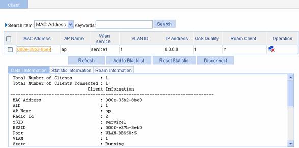
Table 1-8 Description on fields of the client information
|
Field |
Description |
|
MAC address |
MAC address of the client |
|
AID |
Association ID of the client |
|
Radio Id |
Radio ID |
|
SSID |
Service set identifier of the AP |
|
BSSID |
MAC address of the AP |
|
Port |
WLAN-DBSS interface associated with the client |
|
VLAN |
VLAN interface number |
|
State |
State of the client such as running; Backup indicates a backup client. |
|
Power Save Mode |
Client’s power save mode: active or sleep |
|
Wireless Mode |
Wireless mode such as 802.11a, 802.11b, or 802.11g |
|
QoS Mode |
QoS mode: WMM indicates that the WMM function is supported; none indicates that the WMM function is not supported. |
|
Listen Interval (Beacon Interval) |
Number of times the client has waken up to listen to beacon frames |
|
RSSI |
Received signal strength indication. This value indicates the signal strength of AP signals. |
|
SNR |
Signal to Noise Ratio |
|
Rx/Tx Rate |
Represents the reception/transmission rate of the last frame. For the split AP architecture, there is delay because Rx Rate is transmitted from AP to AC periodically depending on the statistics interval. |
|
Client Type |
Client type such as RSN, WPA, or Pre-RSN |
|
Authentication Method |
Authentication method such as open system or shared key |
|
AKM Method |
AKM suite used such as Dot1X or PSK |
|
4-Way Handshake State |
Displays either of the 4-way handshake states: l IDLE: Displayed in initial state. l PTKSTART: Displayed when the 4–way handshake is initialized. l PTKNEGOTIATING: Displayed after sending valid message 3. l PTKINITDONE: Displayed when the 4-way handshake is successful. |
|
Group Key State |
Displays the group key state: l IDLE: Displayed in initial state. l REKEYNEGOTIATE: Displayed after the AC sends the initial message to the client. l REKEYESTABLISHED: Displayed when re-keying is successful. |
|
Encryption Cipher |
Encryption cipher: clear or crypto. |
|
Roam Status |
Displays the roam status: Normal or Fast Roaming |
|
Up Time |
Time for which the client has been associated with the AP. |
The statistics of a client are as shown in Figure 1-10. For the description of the fields in the client statistics information, refer to Table 1-9.
Figure 1-10 Display client statistics
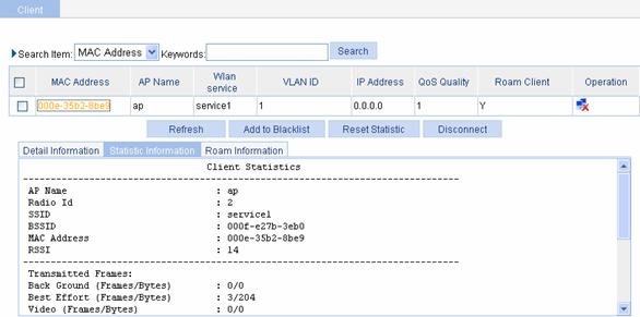
Table 1-9 Description on the fields of client statistics
|
Field |
Description |
|
AP Name |
Name of the associated access point |
|
Radio Id |
Radio ID |
|
SSID |
SSID of the AP |
|
BSSID |
MAC address of the AP |
|
MAC Address |
MAC Address of the client |
|
RSSI |
Received signal strength indication. This value indicates the signal strength of AP signals. |
|
Transmitted Frames |
Number of transmitted frames |
|
Best Effort(Frames/Bytes) |
Statistics of best effort traffic, in frames or in bytes. |
|
Video(Frames/Bytes) |
Statistics of video traffic, in frames or in bytes. |
|
Voice(Frames/Bytes) |
Statistics of voice traffic, in frames or in bytes. |
|
Received Frames |
Number of received frames |
|
Discarded Frames |
Number of discarded frames |
![]()
You can collect statistics of priority queues such as Back Ground, Best Effort, Video and Voice on a QoS client only. Traffic including SVP packets sent and received on a client where QoS is not enabled falls into Best Effort priority queue. Therefore, the queues collected may be different from the queues actually sent. You can collect statistics of priority queues carried in Dot11E or WMM packets; otherwise, statistics collection of priority queues on the receive end may fail.
Client roaming information is as shown in Figure 1-11. For the detailed description of the fields in the client roaming information, refer to Table 1-10.
Figure 1-11 Display client roaming information
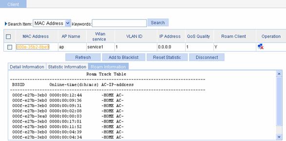
Table 1-10 Fields of the client roaming information
|
Field |
Description |
|
BSSID |
BSSID of the AP associated with the client |
|
Online-time |
Online time of the client |
|
AC-IP-address |
The IP address of the AC connected with the client. When the configured roaming channel type is IPv6, the IPv6 address of the AC is displayed. |