- Table of Contents
-
- H3C WX Series Access Controllers Web-Based Configuration Manual-6PW103
- 00-1Cover
- 01-Quick Start
- 02-Web Overview
- 03-Summary
- 04-Device
- 05-Network
- 06-AP Configuration
- 07-WLAN Service Configuration
- 08-WLAN Roaming Configuration
- 09-Radio Configuration
- 10-Authentication
- 11-Security
- 12-QoS
- 13-SNMP
- 14-Advanced Settings
- Related Documents
-
| Title | Size | Download |
|---|---|---|
| 09-Radio Configuration | 1.15 MB |
l The sample Web page information in this manual was created on the WX5002. The Web page information on your device may vary.
l The models listed in this manual are not applicable to all regions. Please consult the local agents for the models applicable to your region.
Overview
Radio signals are susceptible to surrounding interference. Causes of radio signal attenuation in different directions are very complex. Therefore, we need to make careful plans before deploying a WLAN network. After WLAN deployment, the running parameters still need to be adjusted because the radio environment is always varying due to interference from mobile obstacles, micro-wave ovens and so on. To adapt to environment changes, radio resources such as working channels and transmit power should be dynamically adjusted. Such adjustments are complex and require experienced personnel to implement regularly, which brings high maintenance costs.
WLAN radio resource management (RRM) is a scalable radio resource management solution. Through information collection (APs collect radio environment information in real time), information analysis (The AC analyzes the collected information), decision-making (The AC makes radio resource adjustment configuration according to analysis results), and implementation (APs implement the configuration made by the AC for radio resource optimization), WLAN RRM delivers a real-time, intelligent, integrated radio resource management solution, which enables a WLAN network to quickly adapt to radio environment changes and keep staying in a healthy state.
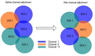
Channel Adjustment
Working channels available in WLANs are few. For example, there are only three working channels in a 2.4G WLAN network. As a result, channel overlapping is very easy to occur. In addition, other radio sources may exist in a WLAN, such as radar, micro-wave ovens, which interfere with the operation of APs. All these problems can be resolved through dynamic channel adjustment.
With dynamic channel adjustment, each AP can be assigned with the best channel in real time to avoid co-channel interference and interference from other radio sources, and thus continuous communication can be ensured to provide for high-reliability data transmission.
Figure 1-1 Dynamic channel adjustment
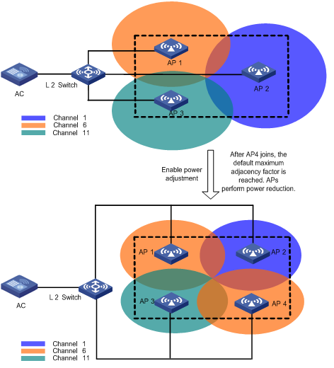
Power Adjustment
Traditionally, an AP has its transmitting power set to the maximum to cover an area as large as possible. This, however, affects the operation of surrounding wireless devices. Therefore, both coverage and capacity need to be considered.
Power adjustment is responsible for real-time radio environment monitoring and dynamic power assignment. When an AP starts for the first time, it uses the maximum transmission power. Then, it collects reports from detected neighbors (which are managed by the same AC) to make a power adjustment decision.
When a new neighbor joins, each AP reduces its transmission power. As shown in Figure 1-2, APs 1, 2 and 3 cover an area. When AP 4 joins, the default maximum number of allowed neighbors (adjacency factor, which is configurable) is reached. Then, the APs perform power adjustment. You can find from the figure that they all reduce their transmission power.
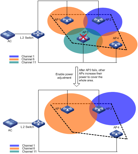
As shown in Figure 1-3, when AP 3 fails, the other APs increase their transmission power to cover the whole area.
Radio Setup
Select Radio > Radio Setup
from the navigation tree, select the desired AP in the list, and click the ![]() icon
to enter the page for AP radio setup page, as shown in Figure 1-4:
icon
to enter the page for AP radio setup page, as shown in Figure 1-4:
Figure 1-4 Radio setup (AP radio setup)
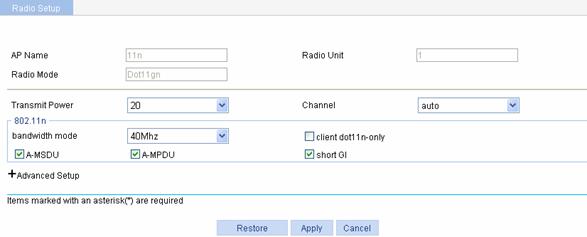
Table 1-1 shows the configuration items of radio setup.
Table 1-1 Configuration items of radio setup
|
Item |
Description |
|
AP Name |
Displays the selected AP. |
|
Radio Unit |
Displays the selected AP’s radios |
|
Radio Mode |
Displays the selected AP’s radio mode, which depends on the AP model and radio unit. |
|
Transmit Power |
Maximum radio transmission power, which varies with country codes, AP models, channels and radio modes. |
|
Channel |
Working channel of the radio, which varies with radio types and country codes. auto: The working channel is selected by the driver in system initialization. |
|
802.11n |
Support for this feature depends on the device model. The option is visible only when an AP supporting 802.11n is selected. |
|
bandwidth mode |
802.11n can bond two adjacent 20-MHz channels together to form a 40-MHz channel. During data forwarding, the two 20-MHz channels can work separately with one acting as the primary channel and the other acting as the secondary channel or work together as a 40-MHz channel. This provides a simple way of doubling the data rate. By default, the channel bandwidth of the 802.11a/n radio is 40 MHz, and that of the 802.11g/n radio is 20 MHz.
If the channel bandwidth of the radio is set to 40 MHz and, a 40 MHz channel is available, the 40 MHz channel is used as the working channel. If no 40 MHz channel is available, a 20 MHz channel is used. |
|
client dot11n-only |
If you select the client dot11n-only check box, non-802.11n clients are prohibited from access. If you want to provide access for all 802.11a/b/g clients, you need to disable this function. |
|
A-MSDU |
Selecting the check box before A-MSDU enables A-MSDU. Similar with MPDU aggregation, multiple MAC Service Data Units (MSDU) can be aggregated into a single A-MSDU. This reduces the MAC header overhead and thus improves MAC layer forwarding efficiency. At present, only A-MSDUs can be received. |
|
A-MPDU |
Selecting the check box before A-MPDU enables A-MPDU. 802.11n introduces the A-MPDU frame format. By using only one PHY header, each A-MPDU can accommodate multiple Message Protocol Data Units (MPDUs) which have their PHY headers removed. This reduces the overhead in transmission and the number of ACK frames to be used, and thus improves network throughput. |
|
short GI |
Selecting the check box before Short GI enables short GI. Delays may occur during receiving radio signals due to factors like multi-path reception. Therefore, a subsequently sent frame may interfere with a previously sent frame. The GI function is used to avoid such interference. It increases the data speed by 10 percent. The short GI function is independent of bandwidth and thus supports both 20MHz and 40MHz bandwidths. |
Figure 1-5 Radio setup (advanced setup)
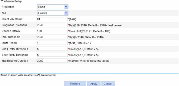
Table 1-2 shows the configuration items of radio setup.
Table 1-2 Configuration items of radio setup
|
Item |
Description |
|
Preamble |
Preamble is a pattern of bits at the beginning of a frame so that the receiver can sync up and be ready for the real data. There are two different kinds of preambles: l Short preamble. A short preamble improves network performance. Therefore, this option is always selected. l Long preamble. A long preamble ensures compatibility between access point and some legacy client devices. Therefore, you can select this option to make legacy client devices support short preamble. Only 802.11b/g supports this configuration. |
|
ANI |
Adaptive Noise Immunity (ANI). After the ANI function is enabled, the device automatically adjusts the noise immunity level according to the surrounding signal environment to eliminate RF interference. l Enable: Enables ANI. l Disable: Disables ANI. |
|
Client Max Count |
Maximum number of associated clients |
|
Fragment Threshold |
Specifies the maximum length of frames that can be transmitted without fragmentation. Fragmentation means to fragment a large frame into small pieces, with each piece transmitted and acknowledged separately. When the length of a frame exceeds the specified fragment threshold value, it is fragmented. A longer frame is less likely to be successfully received. Therefore, in a WLAN where there is high error rate, you can decrease the fragment threshold to increase frame transmission reliability. |
|
Beacon Interval |
Interval for sending beacon frames. Beacon frames are transmitted at a regular interval to allow mobile clients to join the network. Beacon frames are used for a client to identify nearby APs or network control devices. |
|
RTS Threshold |
Request to send (RTS) threshold length. If a frame is larger than this value, the RTS mechanism will be used. RTS is used to avoid data sending collisions in a WLAN. You need to set a rational value: A small value causes RTS packets to be sent more often, thus consuming more of the available bandwidth. However, the more often RTS packets are sent, the quicker the system can recover from interference or collisions. |
|
DTIM Period |
Number of beacon intervals between delivery traffic indication message (DTIM) transmissions. The AP sends buffered broadcast/multicast frames when the DTIM counter reaches 0. |
|
Long Retry Threshold |
Number of retransmission attempts for frames larger than the RTS threshold. |
|
Short Retry Threshold |
Number of retransmission attempts for frames smaller than the RTS threshold if no acknowledgment is received for it. |
|
Max Receive Duration |
Interval for which a frame received by an AP can stay in the buffer memory |
Configuring Data Transmit Rates
Configuring 802.11a/802.11b/802.11g Rates
Select Radio > Rate from the navigation tree to enter the rate setting page, as shown in Figure 1-6:
Figure 1-6 Set 802.11a/802.11b/802.11g rates
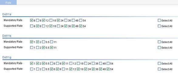
Table 1-3 shows the configuration items of setting rates.
Table 1-3 Configuration items of setting 802.11a/802.11b/802.11g rates
|
Item |
Description |
|
Dot11a |
Configure rates (in Mbps) for 802.11a. By default, mandatory rates are 6, 12, and 24; supported rates are 9, 18, 36, 48, and 54; no rates are disabled. |
|
Dot11b |
Configure rates (in Mbps) for 802.11b. By default, mandatory rates are 1 and 2; supported rates are 5.5 and 11; no rates are disabled. |
|
Dot11g |
Configure rates (in Mbps) for 802.11g. By default, mandatory rates are 1, 2, 5.5, and 11; supported rates are 6, 9, 12, 18, 24, 36, 48, and 54; no rates are disabled. |
Configuring 802.11n Rates
Introduction to MCS
Configuration of mandatory and supported 802.11n rates is achieved by specifying the maximum Modulation and Coding Scheme (MCS) index. The MCS data rate table shows relations between data rates, MCS indexes, and parameters that affect data rates. A sample MCS data rate table in the 20 MHz mode is shown in Table 1-4. For the whole table, refer to IEEE P802.11n D2.00.
Table 1-4 MCS data rate table (20 MHz)
|
MCS index |
Modulation |
R |
Data rate (Mbps) |
|
|
800ns GI |
400ns GI |
|||
|
0 |
BPSK |
1/2 |
6.5 |
7.2 |
|
1 |
QPSK |
1/2 |
13.0 |
14.4 |
|
2 |
QPSK |
3/4 |
19.5 |
21.7 |
|
3 |
16-QAM |
1/2 |
26.0 |
28.9 |
For example, if you specify the maximum MCS index as 5 for mandatory rates, rates corresponding to MCS indexes 0 through 5 are configured as 802.11n mandatory rates.
l Mandatory rates must be supported by the AP and the clients that want to associate with the AP.
l Supported rates allow some clients that support both mandatory and supported rates to choose higher rates when communicating with the AP.
Configuring 802.11n rates
Select Radio > Rate from the navigation tree to enter the rate setting page, as shown in Figure 1-7:
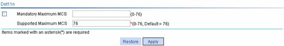
Table 1-5 shows the configuration items of setting 802.11n rate.
Table 1-5 Configuration items of setting 802.11n rate
|
Item |
Description |
|
Mandatory Maximum MCS |
Set the maximum MCS index for 802.11n mandatory rates. |
|
Supported Maximum MCS |
Set the maximum MCS index for 802.11n supported rates. Note that the supported maximum MCS cannot be smaller than the mandatory maximum MCS. |
![]()
To configure 802.11n rates, you must configure mandatory Maximum MCS, and non 802.11n clients cannot associate with the AP.
Configuring Channel Scanning
![]()
For the detailed description of active passive scanning, refer to Access Service in WLAN Service.
Select Radio > Scan from the navigation tree to enter the page for setting channel scanning, as shown in Figure 1-8:
Figure 1-8 Set channel scanning
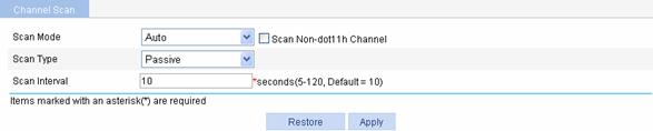
Table 1-6 shows the configuration items of setting channel scanning.
Table 1-6 Configuration items of setting channel scanning
|
Item |
Description |
|
Scan Mode |
Set the scan mode: l Auto: All channels of the country code are scanned. l All: All the channels of the radio band are scanned. |
|
Scan Non-dot11h Channel |
Selecting the Scan Non-dot11h Channel check box enables the function of scanning non-dot11h channels. With this function configured, when the device selects a channel, it scans non-dot11h channels of the country code. If auto channel scan is configured at the same time, a channel is selected among the scanned non-dot11h channels. |
|
Scan Type |
Set the scan type: l Active: In this mode, a client sends a probe request, which enables a client to discover an AP more easily. l Passive: Passive scanning is used by a client when it wants to save battery power. Typically, VoIP clients adopt the passive scanning mode. |
|
Scan Interval |
Set the scan report interval. l If you set a long scan interval, a client is more likely to discover an AP; l If you set a short scan interface, a client can discover an AP more quickly. |
Configuring Calibration
Parameter Setting
Select Radio > Calibration from the navigation tree, and then click Parameters to enter the page for setting channel calibration, as shown in Figure 1-9:
Figure 1-9 Set channel calibration
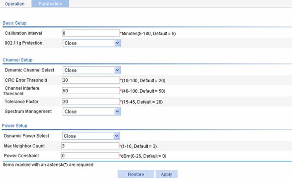
Table 1-7 shows the configuration items of setting channel calibration.
Table 1-7 Configuration items of setting channel calibration
|
Item |
Description |
|
|
Basic Setup |
Calibration Interval |
Channel and power calibration interval. RRM algorithms run periodically at the calibration interval for transmit power control or dynamic frequency selection. |
|
802.11g Protection |
Because dot11b devices cannot be aware of dot11g packets, dot11g protection needs to be enabled for a dot11g device to send RTS/CTS or CTS-to-self packets to dot11b devices, which will defer access to the medium. An AP running 802.11g uses the 802.11g protection function in the following two cases: l An 802.11b client is associated with it. l It detects APs or clients running 802.11b. l Enable: Enables 802.11g protection. l Close: Disables 802.11g protection.
l Enabling 802.11g protection reduces network performance. l Enabling 802.11g protection applies to the second case only because 802.11g protection is always enabled for the first case. |
|
|
Channel Setup |
Dynamic Channel Select |
l Close: Disables the DFS function. l Auto: With auto DFS enabled, an AC performs DFS for a radio when certain trigger conditions are met on the channel and returns the result to the AP after a calibration interval (the default calibration interval is 8 minutes, which can be set through the Calibration Interval option). After that, the AC will make DFS decisions at the calibration interval automatically. l Manual: With one-time DFS configured for a radio, an AC performs DFS for the radio when certain trigger conditions are met on the channel, and returns the result to the AP after a calibration interval. After that, if you want the AC to perform DFS for the radio, you have to make this configuration again.
If you select the manual mode, you need to click Calibration on the Calibration page every time you perform channel calibration. |
|
CRC Error Threshold |
Set the CRC error threshold value, in percentage. |
|
|
Channel Interference Threshold |
Set the channel interference threshold value, in percentage. |
|
|
Tolerance Factor |
A new channel is selected when either the configured CRC error threshold or interference threshold is exceeded on the current channel. However, the new channel is not applied until the quality of the current channel is worse than that of the new channel by the tolerance threshold. |
|
|
Spectrum Management |
l Enable: Enables spectrum management. l Close: Disables spectrum management. |
|
|
Power Setup |
Dynamic Power Select |
l Close: Disables transmit power control (TPC). l Auto: With auto TPC enabled, the AC performs TPC for an AP upon certain interference and returns the result to the AP after a calibration interval (the default calibration interval is 8 minutes, which can be set through the Calibration Interval option). After that, the AC makes TPC decisions at the calibration interval automatically. l Manual: With one-time TPC configured, an AC performs TPC for the AP upon certain interference, and returns the result to the AP after a calibration interval (the default calibration interval is 8 minutes, which can be set through the Calibration Interval option). After that, if you want the AC to perform TPC for the AP, you have to make this configuration again.
If you select manual TPC, you need to click Channel Optimize on the Operation page to complete manual TPC. |
|
Max Neighbor Count |
Specify the number of adjacencies. An AP and its neighbors must be managed by the same AC. |
|
|
Power Constraint |
Set the power constraint for all 802.11a radios. The configured power constraint is advertised in beacons if spectrum management is enabled. |
|
Calibration Operations
![]()
If RRM is not enabled, or the radio to be displayed works on a fixed channel, you can only view the work channel and the power of the radio on the Operations tab in the Radio > Calibration page. Other information such as interference observed and the number of neighbors is displayed when RRM is enabled, that is, dynamic power selection or automatic dynamic frequency selection is enabled. For the configuration of RRM parameters, refer to Parameter Setting.
Displaying channel status
Select Radio > Calibration from the navigation tree, and click the Operations tab to enter the calibration operation page; then click the Channel Status tab, and select the target radio unit to display channel status, as shown in Figure 1-10:
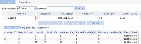
Table 1-8 shows the configuration items of channel status.
Table 1-8 Configuration items of setting channel status
|
Item |
Description |
|
Channel No |
Running channel |
|
Neighbor Num |
Number of neighbors on a channel |
|
Load (%) |
Load observed on a channel |
|
Utilization (%) |
Channel utilization |
|
Interference (%) |
Interference observed on a channel |
|
Packet Error Rate (%) |
Error rate for packets on a channel |
|
Retransmission Rate (%) |
Retransmission rate on a channel |
|
Radar Detect |
Radar detection status |
Displaying neighbor information
Select Radio > Calibration from the navigation tree, and click the Operations tab to enter the calibration operation page; then click the Neighbor Info tab, and select the target radio unit to display neighbor information, as shown in Figure 1-11:
Figure 1-11 Neighbor information
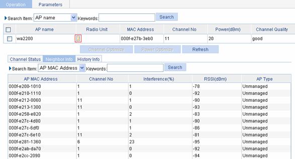
Table 1-9 shows the configuration items of neighbor information.
Table 1-9 Configuration items of setting neighbor information
|
Item |
Description |
|
AP MAC Address |
MAC address of an AP |
|
Chanel No |
Running channel |
|
Interference (%) |
Interference observed on a channel |
|
RSSI (dBm) |
Received signal strength indication (RSSI) of AP, in dBm. |
|
AP Type |
AP type, managed or unmanaged |
Displaying history information
![]()
History information is available only if channel switching or power adjustment occurs after RRM is enabled.
Select Radio > Calibration from the navigation tree, click the Operations tab to enter the calibration operation page, and then click the History Info tab, and select the target radio unit to display history information, as shown in Figure 1-12:
Figure 1-12 History information
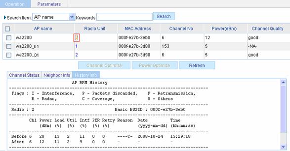
Table 1-9 shows the configuration items of neighbor information.
Table 1-10 Configuration items of setting history information
|
Item |
Description |
|
Radio |
Radio of the AP |
|
Basic BSSID |
MAC address of the radio on the AP |
|
Chl |
Channel number. The operating channel of a radio is running when the radio or power changes. |
|
Power |
The power with which a radio is running when the radio or power changes. |
|
Load |
Load observed on the operating channel when the radio or power changes, in percentage |
|
Util |
Utilization rate of the operating channel when the radio or power changes, in percentage |
|
Intf |
Interference observed on the operating channel when the radio or power changes, in percentage |
|
PER |
Packet error rate observed on the operation channel, in percentage |
|
Retry |
Retransmission rate on a radio when the radio or power changes, in percentage |
|
Reason |
Reason why the radio or power changes, including interference, noise, packet loss, retransmission, reflection and coverage. |
|
Date |
Displays the date when the radio or power changes. |
|
Time |
Displays the time when the radio or power changes. |
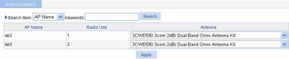
Antenna Setting
Select Radio > Antenna Switch from the navigation tree to enter the page shown in Figure 1-13, where you can select an appropriate antenna type for a radio.
Figure 1-13 Configure antenna switch