- Table of Contents
-
- H3C WX Series Access Controllers Web-Based Configuration Manual-6PW103
- 00-1Cover
- 01-Quick Start
- 02-Web Overview
- 03-Summary
- 04-Device
- 05-Network
- 06-AP Configuration
- 07-WLAN Service Configuration
- 08-WLAN Roaming Configuration
- 09-Radio Configuration
- 10-Authentication
- 11-Security
- 12-QoS
- 13-SNMP
- 14-Advanced Settings
- Related Documents
-
| Title | Size | Download |
|---|---|---|
| 01-Quick Start | 138.69 KB |
l The sample Web page information in this manual was created on the WX5002. The Web page information on your device may vary.
l The models listed in this manual are not applicable to all regions. Please consult the local agents for the models applicable to your region.
Overview
The Quick Start wizard will lead you through the following configuration steps to make your device available for use:
l Guest Wireless Network Configuration
Quick Start
Home Page of the Quick Start Wizard
From the navigation tree, select Quick Start to enter the home page of the Quick Start wizard, as shown in Figure 1-1.
Figure 1-1 Home page of the Quick Start wizard
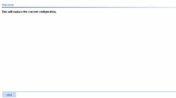
Basic Configuration
From the navigation tree, select Quick Start to enter the home page of the Quick Start wizard, and then click start to enter the basic configuration page, as shown in Figure 1-2.
Figure 1-2 Basic configuration page
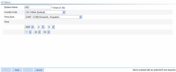
Table 1-1 lists the configuration items of the basic configuration page.
Table 1-1 Configuration items of the basic configuration page
|
Item |
Description |
|
System Name |
Specify the name of the current device. By default, the system name of the device is H3C. |
|
Country Code |
Select the code of the country where you are. This field defines the radio frequency characteristics such as the power and the total number of channels for frame transmission. Before configuring the device, you need to configure the country code correctly. |
|
Time Zone |
Select a time zone for the system. |
|
Time |
Specify the current time and date. |
Admin Configuration
On the basic configuration page, click Next to enter the Admin Configuration page, as shown in Figure 1-3.
Figure 1-3 Admin Configuration page
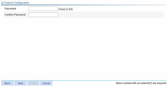
Table 1-2 lists the configuration items of the Admin Configuration page.
Table 1-2 Configuration items of the Admin Configuration page
|
Item |
Description |
|
Password |
Specify the password for user Admin to use to log into the device, in cipher text. |
|
Confirm Password |
Type the password again to confirm the password. |
IP Configuration
On the Admin Configuration page, click Next to enter the IP configuration page, as shown in Figure 1-4.
Figure 1-4 IP configuration page
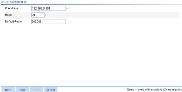
Table 1-3 lists the configuration items of the IP configuration page.
Table 1-3 Configuration items of the IP configuration page
|
Item |
Description |
|
IP Address |
Specify the IP address used for logging in to the Web interface of the device. The default is the IP address of VLAN-interface 1, that is, 192.168.0.100. |
|
Mask |
Specify the IP address mask of VLAN-interface 1. By default, the mask is 24-bit long. |
|
Default Router |
Specify the IP address of the next hop of the default route to the network. By default, it is 0.0.0.0. |
Wireless Configuration
On the IP configuration page, click Next to enter the wireless configuration page, as shown in Figure 1-5.
Figure 1-5 Wireless configuration page

Table 1-4 lists the configuration items of the wireless configuration page.
Table 1-4 Configuration items of the wireless configuration page
|
Item |
Description |
|
Primary Service Authentication Type |
Select the authentication type for the wireless service, which can be: l None: Performs no authentication. l User authentication (802.1X): Performs 802.1X authentication. l Portal: Performs Portal authentication. |
|
Wireless Service |
Specify the Service Set Identifier (SSID) of the current service template. The SSID can contain letters, numbers and underlines, and is case sensitive. It can contain special characters (except ?). No spaces can exist at the beginning and end of the string. |
|
Encrypt |
Select or deselect this check box to specify whether to encrypt the service template. |
|
Default Vlan Tag |
l If you select Yes, you configure the link type of the ports in VLAN 1 as hybrid and specify that packets to be sent out from VLAN 1 carry the VLAN tag. This configuration requires that no trunk port exists in the VLAN. If there is any trunk port in VLAN 1, you need to change the link type of the port to access. l If you select No, the above operations are not performed for the ports in VLAN 1. |
RADIUS Configuration
On the wireless configuration page, select User authentication (802.1X) for the Primary Service Authentication Type field to enter the RADIUS configuration page, as shown in Figure 1-6.
Figure 1-6 RADIUS configuration page
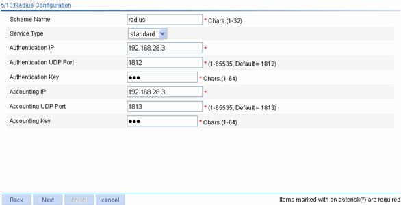
Table 1-5 lists the configuration items of the RADIUS configuration page.
Table 1-5 Configuration items of the RADIUS configuration page
|
Item |
Description |
|
Scheme Name |
Specify a name for the RADIUS scheme to be created. |
|
Service Type |
Select the type of the RADIUS server. Two types are available: standard and enhanced: l extended: Specifies extended RADIUS server, which is usually a CAMS server. In this case, the RADIUS client (access device) and the RADIUS server exchange packets based on the specifications and packet format definitions of a private RADIUS protocol. l standard: Specifies the standard RADIUS server. In this case, the RADIUS client (access device) and the RADIUS server exchange packets based on the specifications and packet format definitions of the standard RADIUS protocols (RFC 2138, RFC 2139, and the updates). |
|
Authentication IP |
Type the IP address of the RADIUS authentication server. |
|
Authentication UDP Port |
Type the UDP port number of the RADIUS authentication server. |
|
Authentication Key |
Type the shared key for RADIUS authentication. |
|
Accounting IP |
Type the IP address of the RADIUS accounting server. |
|
Accounting UDP Port |
Type the port number of the RADIUS accounting server. |
|
Accounting Key |
Type the shared key for RADIUS accounting. |
Portal Configuration
On the wireless configuration page, select Portal for the Primary Service Authentication Type field, perform other required configurations, and click Next. You will enter the RADIUS configuration page, where you can perform RADIUS configuration. Then, click Next to enter the portal configuration page, as shown in Figure 1-7.
Figure 1-7 Portal configuration page
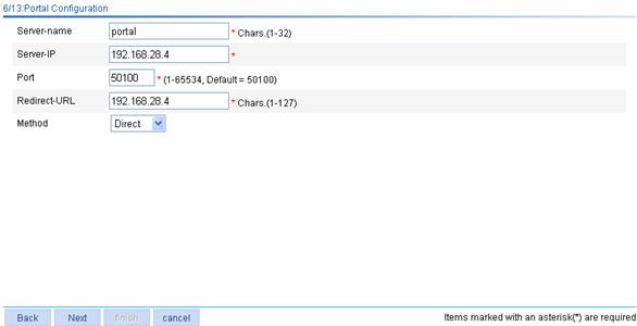
Table 1-6 lists the configuration items of the portal configuration page.
Table 1-6 Configuration items of the portal configuration page
|
Item |
Description |
|
Server-name |
Specify the system name of the portal server. |
|
Server-IP |
Type the IP address of the portal server. |
|
Port |
Type the port number of the portal server. |
|
Redirect-URL |
Type the URL of the portal authentication server to which all the HTTP requests in the segment are redirected. |
|
Method |
Specify the portal authentication method to be used, which can be: l Direct: Before authentication, a user manually configures an IP address or directly obtains a public IP address through DHCP, and can access only the portal server and predefined free websites. After passing authentication, the user can access the network resources. The authentication process of direct authentication is relatively simple than that of the re-DHCP authentication. l Layer3: Layer 3 authentication is similar to direct authentication but allows Layer 3 forwarding devices to be present between the authentication client and the access device. l Redhcp: Before authentication, a user gets a private IP address through DHCP and can access only the portal server and predefined free websites. After passing authentication, the user is allocated a public IP address and can access the network resources. |
Encryption Configuration
You may enter the encryption configuration page in two ways:
l On the wireless configuration page, select User authentication (802.1X) for the Primary Service Authentication Type field and click Next to enter the RADIUS configuration page. Complete RADIUS configuration and then click Next.
l On the wireless configuration page, select Portal for the Primary Service Authentication Type field and click Next to enter the RADIUS configuration page. Complete RADIUS configuration and click Next to enter the portal configuration page. Then, complete portal authentication and click Next.
The encryption configuration page is as shown in Figure 1-8.
Figure 1-8 Encryption configuration page
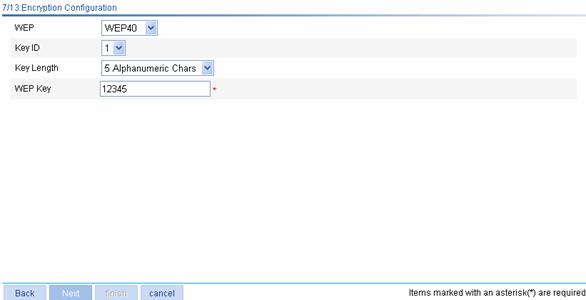
Table 1-7 lists the configuration items of the encryption configuration page.
Table 1-7 Configuration items of the encryption configuration page
|
Item |
Description |
|
WEP |
Select the key type of the WEP encryption mechanism, which can be WEP40 and WEP104. |
|
Key ID |
Select the WEP key index, which can be 1, 2, 3, or 4. Each number represents one of the four static keys of WEP. The selected key index will be used for frame encryption and decryption |
|
Key Length |
Select the key length. l When the key type is WEP40, the key length can be five alphanumeric characters or ten hexadecimal characters. l When the key type is WEP104, the key length can be 13 alphanumeric characters or 26 hexadecimal characters. |
|
WEP Key |
Type the WEP key. |
Guest Wireless Network Configuration
On the encryption configuration page, click Next to enter the guest wireless network configuration page, as shown in Figure 1-9.
Figure 1-9 Guest wireless network configuration page
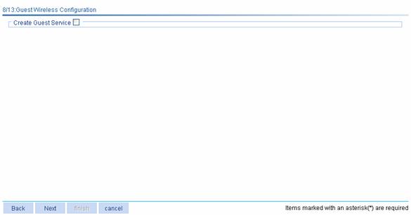
Select the Create Guest service check box to display the guest service configuration page, as shown in Figure 1-10.
Figure 1-10 Guest service configuration page

Table 1-8 lists the configuration items of the guest service configuration page.
Table 1-8 Configuration items of the guest service configuration page
AP Configuration
On the guest service configuration page, click Next to enter the AP configuration page, as shown in Figure 1-11. You can configure an AP and click Add. The section at the bottom of the page displays all existing APs.
Figure 1-11 AP configuration page
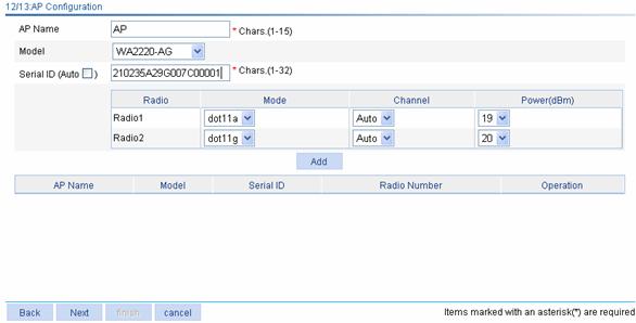
Table 1-9 lists the configuration items of the AP configuration page.
![]()
You can configure multiple APs on the page.
Table 1-9 Configuration items of the AP configuration page
|
Item |
Description |
|
AP Name |
Specify the name of the AP connected with the access controller (AC). |
|
Mode |
Specify the type of the AP connected with the AC. |
|
Sequence Number |
Specify the sequence number of the AP connected with the AC. If the Auto check box is not selected, you need to manually type a sequence number. You can also select Auto check box to enable the automatic AP discovery function so that the AP can connect with the AC automatically. If there are a large number of APs, you can enable the automatic AP discovery function to relieve yourself of the burden to configure the AP sequence numbers. |
|
Radio |
Specify the radio unit. |
|
Mode |
The value of this item depends on the type of the AP and the radio unit. |
|
Power |
Select the transmission power. |
|
Channel |
Select the channel to be used. |
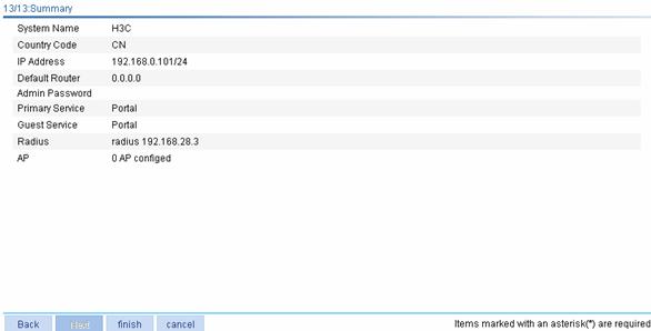
Configuration Summary
On the AP configuration page, click Next to enter the configuration summary page, as shown in Figure 1-12. The configuration summary page will display all configurations you have made. Click finish to save your configurations.
Figure 1-12 Configuration summary page