- Table of Contents
-
- H3C WX Series Access Controllers Web-Based Configuration Manual-6PW103
- 00-1Cover
- 01-Quick Start
- 02-Web Overview
- 03-Summary
- 04-Device
- 05-Network
- 06-AP Configuration
- 07-WLAN Service Configuration
- 08-WLAN Roaming Configuration
- 09-Radio Configuration
- 10-Authentication
- 11-Security
- 12-QoS
- 13-SNMP
- 14-Advanced Settings
- Related Documents
-
| Title | Size | Download |
|---|---|---|
| 12-QoS | 476.97 KB |
Table of Contents
Configuring a Rule for a Basic IPv4 ACL
Configuring a Rule for an Advanced IPv4 ACL
Configuring a Rule for an Ethernet Frame Header ACL
Configuring a Rule for a Basic IPv6 ACL
Configuring a Rule for an Advanced IPv6 ACL
Configuring Line Rate on a Port
Configuring Priority Trust Mode on a Port
Configuring Classification Rules
Configuring Actions for a Traffic Behavior
Configuring Classifier-Behavior Associations for the Policy
Setting Client EDCA Parameters
4 ACL/QoS Configuration Examples
l The sample Web page information in this manual was created on the WX5002.
l In the sentence “Support for this feature depends on your device model” in this manual, the “device” collectively refers to the H3C WX series access controller products. The following table describes the support of the H3C WX series access controller products for features.
l The models listed in this manual are not applicable to all regions. Please consult the local agents for the models applicable to your region.
The following table shows the support of the H3C WX series access controller products for features:
|
Feature |
WX5000 series |
WX6000 series |
WX3000 series |
||||||
|
WX5002 |
LS8M1WCMA0 |
WX5004 |
WX6103 |
LSQM1WCMB0 |
LSBM1WCM2A0 |
WX3024 |
WX3010 |
WX3008 |
|
|
IPv6 ACL |
Supported |
Supported |
Supported |
Supported |
Supported |
Not supported |
Not supported |
Not supported |
Not supported |
|
Line rate |
Supported |
Supported |
Not supported |
Not supported |
Not supported |
Not supported |
Not supported |
Not supported |
Not supported |
ACL Overview
With the growth of network scale and network traffic, network security and bandwidth allocation become more and more critical to network management. Packet filtering can be used to efficiently prevent illegal access to networks and to control network traffic and save network resources. One way to implement packet filtering is to use access control lists (ACLs).
An ACL is a set of rules (or a set of permit or deny statements) for determining which packets can pass and which ones should be rejected based on matching criteria such as source address, destination address, and port number. ACLs are widely used in technologies where traffic identification is desired, such as firewall and QoS.
Introduction to IPv4 ACL
IPv4 ACL Classification
IPv4 ACLs supported on the devices, identified by ACL numbers, fall into three categories, as shown in Table 1-1.
|
Category |
ACL number range |
Matching criteria |
|
Basic IPv4 ACL |
2000 to 2999 |
Source IP address |
|
Advanced IPv4 ACL |
3000 to 3999 |
Source IP address, destination IP address, protocol carried over IP, and other Layer 3 or Layer 4 protocol header information |
|
Ethernet frame header ACL |
4000 to 4999 |
Layer 2 protocol header fields such as source MAC address, destination MAC address, 802.1p priority, and link layer protocol type |
IPv4 ACL Match Order
An ACL may consist of multiple rules, which specify different matching criteria. These criteria may have overlapping or conflicting parts. The match order is for determining how packets should be matched against the rules.
There are two types of IPv4 ACL match orders:
l config: Packets are compared against ACL rules in the order that the rules are configured.
l auto: Packets are compared against ACL rules in the depth-first match order.
The term depth-first match has different meanings for different types of IPv4 ACLs, as shown in Table 1-2.
Table 1-2 Depth-first match for IPv4 ACLs
|
IPv4 ACL category |
Depth-first match procedure |
|
Basic IPv4 ACL |
1) Sort rules by source IP address wildcard and compare packets against the rule configured with more zeros in the source IP address wildcard. 2) In case of a tie, compare packets against the rule configured first. |
|
Advanced IPv4 ACL |
1) Sort rules by VPN instance first and compare packets against the rule configured with a VPN instance. 2) In case of a tie, look at the protocol carried over IP. A rule with no limit to the protocol type (that is, configured with the ip keyword) has the lowest precedence. Rules each of which has a single specified protocol type are of the same precedence level. 3) If the protocol types have the same precedence, look at the source IP address wildcards. Then, compare packets against the rule configured with more zeros in the source IP address wildcard. 4) If the numbers of zeros in the source IP address wildcards are the same, look at the destination IP address wildcards. Then, compare packets against the rule configured with more zeros in the destination IP address wildcard. 5) If the numbers of zeros in the destination IP address wildcards are the same, look at the Layer 4 port number ranges, namely the TCP/UDP port number ranges. Then compare packets against the rule configured with the smaller port number range. 6) If the port number ranges are the same, compare packets against the rule configured first. |
|
Ethernet frame header ACL |
1) Sort rules by source MAC address mask first and compare packets against the rule configured with more ones in the source MAC address mask. 2) If two rules are present with the same number of ones in their source MAC address masks, look at the destination MAC address masks. Then, compare packets against the rule configured with more ones in the destination MAC address mask. 3) If the numbers of ones in the destination MAC address masks are the same, compare packets against the one configured first. |
The comparison of a packet against ACL rules stops immediately after a match is found. The packet is then processed as per the rule.
Fragments Filtering with IPv4 ACL
Traditional packet filtering performs match operation on only the first fragments. All subsequent non-first fragments are handled in the way the first fragments are handled. As attackers may fabricate non-first fragments to attack your network, this results in security risks.
To address the risks, the device implements the following packet filtering functions:
l IP-based filtering on all fragments.
l Standard match and exact match of ACLs containing advanced information such as TCP/UDP port number and ICMP type. The default is standard match.
![]()
l Standard match considers only Layer 3 information.
l Exact match considers all header information defined in ACL rules.
These two ACL rule matching approaches are available only on firewalls.
Introduction to IPv6 ACL
IPv6 ACL categories
IPv6 ACLs supported on the devices, identified by ACL numbers, fall into two categories, as shown in Table 1-3.
|
Category |
ACL number |
Matching criteria |
|
Basic IPv6 ACL |
2000 to 2999 |
Source IPv6 address |
|
Advanced IPv6 ACL |
3000 to 3999 |
Source IPv6 address, destination IPv6 address, protocol carried over IPv6, and other Layer 3 or Layer 4 protocol header information |
IPv6 ACL Match Order
An ACL may consist of multiple rules, which specify different matching criteria. These criteria may have overlapping or conflicting parts. The match order is for determining how packets should be matched against the rules.
There are two types of IPv6 ACL match orders:
l config: Packets are compared against ACL rules in the order the rules are configured.
l auto: Packets are compared against ACL rules in the depth-first match order.
The term depth-first match has different meanings for different types of IPv6 ACLs, as shown in Table 1-4.
Table 1-4 Depth-first match for IPv6 ACLs
|
IPv6 ACL Category |
Depth-first match procedure |
|
Basic IPv6 ACL |
1) Sort rules by source IPv6 address prefix first and compare packets against the rule configured with a longer prefix for the source IPv6 address. 2) In case of a tie, compare packets against the rule configured first. |
|
Advanced IPv6 ACL |
1) Look at the protocol type field in the rules first. A rule with no limit to the protocol type (that is, configured with the ipv6 keyword) has the lowest precedence. Rules each of which has a single specified protocol type are of the same precedence level. Compare packets against the rule with the highest precedence. 2) In case of a tie, look at the source IPv6 address prefixes. Then, compare packets against the rule configured with a longer prefix for the source IPv6 address. 3) If the prefix lengths for the source IPv6 addresses are the same, look at the destination IPv6 address prefixes. Then, compare packets against the rule configured with a longer prefix for the destination IPv6 address. 4) If the prefix lengths for the destination IPv6 addresses are the same, look at the Layer 4 port number ranges, namely the TCP/UDP port number ranges. Then compare packets against the rule configured with the smaller port number range. 5) If the port number ranges are the same, compare packets against the rule configured first. |
The comparison of a packet against ACL rules stops immediately after a match is found. The packet is then processed as per the rule.
Effective Period of an ACL
You can control when a rule can take effect by referencing a time range in the rule.
ACL Step
![]()
Currently, the Web interface does not support ACL step configuration.
Meaning of the step
The step defines the difference between two neighboring numbers that are automatically assigned to ACL rules by the device. For example, with a step of 5, rules are automatically numbered 0, 5, 10, 15, and so on. By default, the step is 5.
Whenever the step changes, the rules are renumbered, starting from 0. For example, if four rules are numbered 0, 5, 10, and 15 respectively, changing the step from 5 to 2 will cause the rules to be renumbered 0, 2, 4, and 6.
Benefits of using the step
With the step and rule numbering/renumbering mechanism, you do not need to assign numbers to rules when defining them. The system will assign a newly defined rule a number that is the smallest multiple of the step bigger than the current biggest number. For example, with a step of five, if the biggest number is currently 28, the newly defined rule will get a number of 30. If the ACL has no rule defined already, the first defined rule will get a number of 0.
Another benefit of using the step is that it allows you to insert new rules between existing ones as needed. For example, after creating four rules numbered 0, 5, 10, and 15 in an ACL with a step of five, you can insert a rule numbered 1.
Configuring an ACL
Configuration Task List
Configuring an IPv4 ACL
Table 1-5 lists the IPv4 ACL configuration tasks.
Table 1-5 IPv4 ACL configuration task list
|
Task |
Remarks |
|
Optional A rule referencing a time range takes effect only during the specified time range. |
|
|
Required The category of the created ACL depends on the ACL number that you specify. |
|
|
Required Complete one of the three tasks according to the ACL category. |
|
Configuring an IPv6 ACL
Table 1-6 lists the IPv6 ACL configuration tasks.
Table 1-6 IPv6 ACL configuration task list
|
Task |
Remarks |
|
Optional A rule referencing a time range takes effect only during the specified time range. |
|
|
Required The category of the created IPv6 ACL depends on the ACL number that you specify. |
|
|
Required Complete one of the tasks according to the ACL category. |
|
Configuring a Time Range
Select QoS > Time Range from the navigation tree and then select the Create tab to enter the time range configuration page, as shown in Figure 1-1.
Figure 1-1 The page for creating a time range
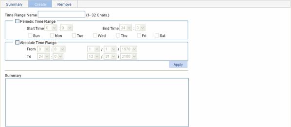
Table 1-7 describes the configuration items for creating a time range.
Table 1-7 Time range configuration items
|
Item |
Description |
||
|
Time Range Name |
Set the name for the time range. |
||
|
Periodic Time Range |
Start Time |
Set the start time of the periodic time range. |
These items are available after you select the Periodic Time Range check box. |
|
End Time |
Set the end time of the periodic time range. The end time must be greater than the start time. |
||
|
Sun, Mon, Tue, Wed, Thu, Fri, and Sat. |
Select the day or days of the week on which the periodic time range is valid. You can select any combination of the days of the week. |
||
|
Absolute Time Range |
From |
Set the start time of the absolute time range. The time of the day is in the hh:mm format (24-hour clock), and the date is in the MM/DD/YYYY format. |
These items are available after you select the Absolute Time Range check box. |
|
To |
Set the end time of the absolute time range. The time of the day is in the hh:mm format (24-hour clock), and the date is in the MM/DD/YYYY format. The end time must be greater than the start time. |
||
Return to IPv4 ACL configuration task list.
Return to IPv6 ACL configuration task list.
Creating an IPv4 ACL
Select QoS > ACL IPv4 from the navigation tree and then select the Create tab to enter the IPv4 ACL configuration page, as shown in Figure 1-2.
Figure 1-2 The page for creating an IPv4 ACL
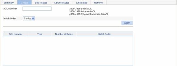
Table 1-8 describes the configuration items for creating an IPv4 ACL.
Table 1-8 IPv4 ACL configuration items
|
Item |
Description |
|
ACL Number |
Set the number of the IPv4 ACL. |
|
Match Order |
Set the match order of the ACL. Available values are: l Config: Packets are compared against ACL rules in the order that the rules are configured. l Auto: Packets are compared against ACL rules in the depth-first match order. |
Return to IPv4 ACL configuration task list.
Configuring a Rule for a Basic IPv4 ACL
Select QoS > ACL IPv4 from the navigation tree and then select the Basic Setup tab to enter the rule configuration page for a basic IPv4 ACL, as shown in Figure 1-3.
Figure 1-3 The page for configuring an basic IPv4 ACL
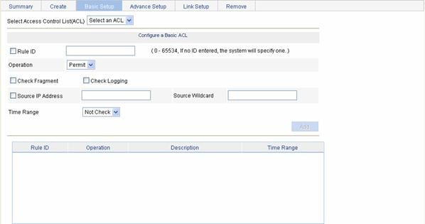
Table 1-9 describes the configuration items for creating a rule for a basic IPv4 ACL.
Table 1-9 Configuration items for a basic IPv4 ACL rule
|
Item |
Description |
|
Select Access Control List (ACL) |
Select the basic IPv4 ACL for which you want to configure rules. Available ACLs are basic IPv4 ACLs that have been configured. |
|
Rule ID |
Select the Rule ID check box and type a number for the rule. If you do not specify the rule number, the system will assign one automatically. |
|
Operation |
Select the operation to be performed for IPv4 packets matching the rule. l Permit: Allows matched packets to pass. l Deny: Drops matched packets. |
|
Check Fragment |
Select this check box to apply the rule to only non-first fragments. If you do no select this check box, the rule applies to all fragments and non-fragments. |
|
Check Logging |
Select this check box to keep a log of matched IPv4 packets. A log entry contains the ACL rule number, operation for the matched packets, protocol that IP carries, source/destination address, source/destination port number, and number of matched packets. |
|
Source IP Address |
Select the Source IP Address check box and type a source IPv4 address and source wildcard, in dotted decimal notation. |
|
Source Wildcard |
|
|
Time Range |
Select the time range during which the rule takes effect. Available time ranges are those that have been configured. |
Return to IPv4 ACL configuration task list.
Configuring a Rule for an Advanced IPv4 ACL
Select QoS > ACL IPv4 from the navigation tree and then select the Advance Setup tab to enter the rule configuration page for an advanced IPv4 ACL, as shown in Figure 1-4.
Figure 1-4 The page for configuring an advanced IPv4 ACL

Table 1-10 describes the configuration items for creating a rule for an advanced IPv4 ACL.
Table 1-10 Configuration items for an advanced IPv4 ACL rule
|
Item |
Description |
||
|
Select Access Control List (ACL) |
Select the advanced IPv4 ACL for which you want to configure rules. Available ACLs are advanced IPv4 ACLs that have been configured. |
||
|
Rule ID |
Select the Rule ID check box and type a number for the rule. If you do not specify the rule number, the system will assign one automatically. |
||
|
Operation |
Select the operation to be performed for IPv4 packets matching the rule. l Permit: Allows matched packets to pass. l Deny: Drops matched packets. |
||
|
Check Fragment |
Select this check box to apply the rule to only non-first fragments. If you do no select this check box, the rule applies to all fragments and non-fragments. |
||
|
Check Logging |
Select this check box to keep a log of matched IPv4 packets. A log entry contains the ACL rule number, operation for the matched packets, protocol that IP carries, source/destination address, source/destination port number, and number of matched packets. |
||
|
IP Address Filter |
Source IP Address |
Select the Source IP Address check box and type a source IPv4 address and source wildcard, in dotted decimal notation. |
|
|
Source Wildcard |
|||
|
Destination IP Address |
Select the Source IP Address check box and type a source IP address and source wildcard, in dotted decimal notation. |
||
|
Destination Wildcard |
|||
|
Protocol |
Select the protocol to be carried by IP. If you select 1 ICMP, you can configure the ICMP message type and code; if you select 6 TCP or 17 UDP, you can configure the TCP or UDP specific items. |
||
|
ICMP Type |
Named ICMP Type |
Specify the ICMP message type and code. These items are available only when you select 1 ICMP from the Protocol drop-down box. If you select Other from the Named ICMP Type drop-down box, you need to type values in the ICMP Type and ICMP Code fields. Otherwise, the two fields will take the default values, which cannot be changed. |
|
|
ICMP Type |
|||
|
ICMP Code |
|||
|
TCP/UDP Port |
Check Established |
Select this check box to make the rule match packets used for establishing and maintaining TCP connections. These items are available only when you select 6 TCP from the Protocol drop-down box. On a router, a rule with this item configured matches TCP connection packets with the ACK or RST flag. The usage and availability of this item on switches depend on the device model. |
|
|
Source |
Operator |
Select the operators and type the source port numbers and destination port numbers as required. These items are available only when you select 6 TCP or 17 UDP from the Protocol drop-down box. Different operators have different configuration requirements for the port number fields: l Not Check: The following port number fields cannot be configured. l Range: The following port number fields must be configured to define a port range. l Other values: The first port number field must be configured and the second must not. |
|
|
Port |
|||
|
To Port |
|||
|
Destination |
Operator |
||
|
Port |
|||
|
To Port |
|||
|
Precedence Filter |
DSCP |
Specify the DSCP priority. |
|
|
TOS |
Specify the ToS preference. |
||
|
Precedence |
Specify the IP precedence. |
||
|
Time Range |
Select the time range during which the rule takes effect. Available time ranges are those that have been configured. |
||
Return to IPv4 ACL configuration task list.
Configuring a Rule for an Ethernet Frame Header ACL
Select QoS > ACL IPv4 from the navigation tree and then select the Link Setup tab to enter the rule configuration page for an Ethernet frame header IPv4 ACL, as shown in Figure 1-5.
Figure 1-5 The page for configuring a rule for an Ethernet frame header ACL
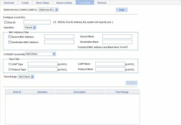
Table 1-11 describes the configuration items for creating a rule for an Ethernet frame header IPv4 ACL.
Table 1-11 Configuration items for an Ethernet frame header IPv4 ACL rule
|
Item |
Description |
|
|
Select Access Control List (ACL) |
Select the Ethernet frame header IPv4 ACL for which you want to configure rules. Available ACLs are Ethernet frame header IPv4 ACLs that have been configured. |
|
|
Rule ID |
Select the Rule ID check box and type a number for the rule. If you do not specify the rule number, the system will assign one automatically. |
|
|
Operation |
Select the operation to be performed for IPv4 packets matching the rule. l Permit: Allows matched packets to pass. l Deny: Drops matched packets. |
|
|
MAC Address Filter |
Source MAC Address |
Select the Source MAC Address check box and type a source MAC address and wildcard. |
|
Source Mask |
||
|
Destination MAC Address |
Select the Destination MAC Address check box and type a destination MAC address and wildcard. |
|
|
Destination Mask |
||
|
COS(802.1p priority) |
Specify the 802.1p priority for the rule. |
|
|
Type Filter |
LSAP Type |
Select the LSAP Type check box and specify the DSAP and SSAP fields in the LLC encapsulation by configuring the following two items: l LSAP Type: Indicates the frame encapsulation format. l LSAP Mask: Indicates the LSAP wildcard. |
|
LSAP Mask |
||
|
Protocol Type |
Select the Protocol Type check box and specify the link layer protocol type by configuring the following two items: l Protocol Type: Indicates the frame type. It corresponds to the type-code field of Ethernet_II and Ethernet_SNAP frames. l Protocol Mask: Indicates the wildcard. |
|
|
Protocol Mask |
||
|
Time Range |
Select the time range during which the rule takes effect. Available time ranges are those that have been configured. |
|
Return to IPv4 ACL configuration task list.
Creating an IPv6 ACL
Select QoS > ACL IPv6 from the navigation tree and then select the Create tab to enter the IPv6 ACL configuration page, as shown in Figure 1-6.
Figure 1-6 The page for creating an IPv6 ACL
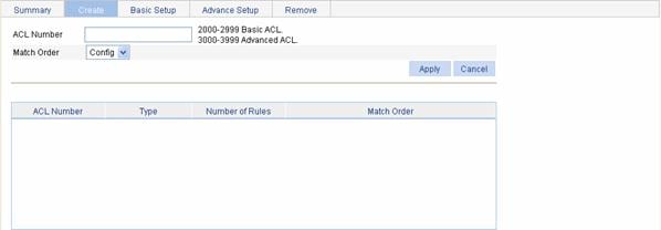
Table 1-12 describes the configuration items for creating an IPv6 ACL.
Table 1-12 IPv6 ACL configuration items
|
Item |
Description |
|
ACL Number |
Type a number for the IPv6 ACL. |
|
Match Order |
Select a match order for the ACL. Available values are: l Config: Packets are compared against ACL rules in the order the rules are configured. l Auto: Packets are compared against ACL rules in the depth-first match order. |
Return to IPv6 ACL configuration task list.
Configuring a Rule for a Basic IPv6 ACL
Select QoS > ACL IPv6 from the navigation tree and then select the Basic Setup tab to enter the rule configuration page for a basic IPv6 ACL, as shown in Figure 1-7.
Figure 1-7 The page for configuring a rule for a basic IPv6 ACL
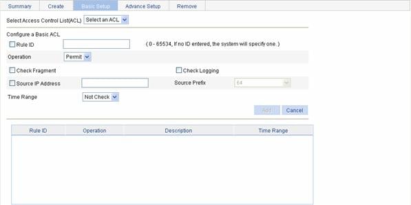
Table 1-13 describes the configuration items for creating a rule for a basic IPv6 ACL.
Table 1-13 Configuration items for a basic IPv6 ACL rule
|
Item |
Description |
|
Select Access Control List (ACL) |
Select the basic IPv6 ACL for which you want to configure rules. Available ACLs are basic IPv6 ACLs that have been configured. |
|
Rule ID |
Select the Rule ID check box and type a number for the rule. If you do not specify the rule number, the system will assign one automatically. |
|
Operation |
Select the operation to be performed for IPv6 packets matching the rule. l Permit: Allows matched packets to pass. l Deny: Drops matched packets. |
|
Check Fragment |
Select this check box to apply the rule to only non-first fragments. If you do no select this check box, the rule applies to all fragments and non-fragments. |
|
Check Logging |
Select this check box to keep a log of matched IPv6 packets. A log entry contains the ACL rule number, operation for the matched packets, protocol that IP carries, source/destination address, source/destination port number, and number of matched packets. |
|
Source IP Address |
Select the Source IP Address check box and type a source IPv6 address and prefix length. The IPv6 address must be in a format like X:X::X:X. An IPv6 address consists of eight 16-bit long fields, each of which is expressed with two hexadecimal numbers and separated from its neighboring fields by colon (:). |
|
Source Prefix |
|
|
Time Range |
Select the time range during which the rule takes effect. Available time ranges are those that have been configured. |
Return to IPv6 ACL configuration task list.
Configuring a Rule for an Advanced IPv6 ACL
Select QoS > ACL IPv6 from the navigation tree and then select the Advance Setup tab to enter the rule configuration page for an advanced IPv6 ACL, as shown in Figure 1-8.
Figure 1-8 The page for configuring a rule for an advanced IPv6 ACL

Table 1-14 describes the configuration items for creating a rule for an advanced IPv6 ACL.
Table 1-14 Configuration items for an advanced IPv6 ACL rule
|
Item |
Description |
||
|
Select Access Control List (ACL) |
Select the advanced IPv6 ACL for which you want to configure rules. Available ACLs are advanced IPv6 ACLs that have been configured. |
||
|
Rule ID |
Select the Rule ID check box and type a number for the rule. If you do not specify the rule number, the system will assign one automatically. |
||
|
Operation |
Select the operation to be performed for IPv6 packets matching the rule. l Permit: Allows matched packets to pass. l Deny: Drops matched packets. |
||
|
Check Fragment |
Select this check box to apply the rule to only non-first fragments. If you do no select this check box, the rule applies to all fragments and non-fragments. |
||
|
Check Logging |
Select this check box to keep a log of matched IPv6 packets. A log entry contains the ACL rule number, operation for the matched packets, protocol that IP carries, source/destination address, source/destination port number, and number of matched packets. |
||
|
IP Address Filter |
Source IP Address |
Select the Source IP Address check box and type a source IPv6 address and prefix length. The IPv6 address must be in a format like X:X::X:X. An IPv6 address consists of eight 16-bit long fields, each of which is expressed with two hexadecimal numbers and separated from its neighboring fields by colon (:). |
|
|
Source Prefix |
|||
|
Destination IP Address |
Select the Destination IP Address check box and type a destination IPv6 address and prefix length. The IPv6 address must be in a format like X:X::X:X. An IPv6 address consists of eight 16-bit long fields, each of which is expressed with two hexadecimal numbers and separated from its neighboring fields by colon (:). |
||
|
Destination Prefix |
|||
|
Protocol |
Select the protocol to be carried by IP. If you select 58 ICMPv6, you can configure the ICMP message type and code; if you select 6 TCP or 17 UDP, you can configure the TCP or UDP specific items. |
||
|
ICMPv6 Type |
Named ICMPv6 Type |
Specify the ICMPv6 message type and code. These items are available only when you select 58 ICMPv6 from the Protocol drop-down box. If you select Other from the Named ICMPv6 Type drop-down box, you need to type values in the ICMPv6 Type and ICMPv6 Code fields. Otherwise, the two fields will take the default values, which cannot be changed. |
|
|
ICMPv6 Type |
|||
|
ICMPv6 Code |
|||
|
TCP/UDP Port |
Source |
Operator |
Select the operators and type the source port numbers and destination port numbers as required. These items are available only when you select 6 TCP or 17 UDP from the Protocol drop-down box. Different operators have different configuration requirements for the port number fields: l Not Check: The following port number fields cannot be configured. l Range: The following port number fields must be configured to define a port range. l Other values: The first port number field must be configured and the second must not. |
|
Port |
|||
|
To Port |
|||
|
Destination |
Operator |
||
|
Port |
|||
|
Port |
|||
|
Time Range |
Select the time range during which the rule takes effect. Available time ranges are those that have been configured. |
||
Return to IPv6 ACL configuration task list.
Configuration Guidelines
When configuring an ACL, note that:
1) When defining rules in an ACL, you do not necessarily assign them numbers; the system can do this automatically. Refer to ACL Step.
2) You cannot create a rule with, or modify a rule to have, the same permit/deny statement as an existing rule in the ACL.
3) You can only modify the existing rules of an ACL that uses the match order of config. When modifying a rule of such an ACL, you may choose to change just some of the settings, in which case the other settings remain the same.
2 QoS Configuration
Overview
QoS Overview
Quality of Service (QoS) is a concept concerning service demand and supply. It reflects the ability to meet customer needs. Generally, QoS focuses on improving services under certain conditions rather than grading services precisely.
In an internet, QoS evaluates the ability of the network to forward packets using different services. The evaluation can be based on different criteria because the network may provide various services. Generally, QoS refers to the ability to provide improved service by solving the core issues such as delay, jitter, and packet loss ratio in the packet forwarding process.
Traditional packet forwarding services
On traditional IP networks, devices treat all packets equally and handle them using the first in first out (FIFO) policy. All packets share the resources of the network and devices. How many resources the packets can obtain completely depends on the time they arrive. This service is called best-effort. It delivers packets to their destinations as possibly as it can, without any guarantee for delay, jitter, packet loss ratio, reliability and so on.
This service policy is only suitable for applications insensitive to bandwidth and delay, such as WWW, file transfer and e-mail.
New requirements from emerging applications
The Internet has been growing along with the fast development of networking technologies. More and more people use the Internet to transmit data, share video and do a lot of other things.
Besides traditional applications such as WWW, e-mail and FTP, network users are experiencing new services, such as tele-education, telemedicine, video telephone, videoconference and Video-on-Demand (VoD). Enterprise users expect to connect their regional branches together with VPN technologies to carry out operational applications, for instance, to access the database of the company or to monitor remote devices through Telnet.
These new applications have one thing in common, that is, they all have special requirements for bandwidth, delay, and jitter. For example, videoconference and VoD require high bandwidth, low delay and jitter. As for mission-critical applications, such as transactions and Telnet, they may not require high bandwidth but do require low delay and preferential service during congestion.
The emerging applications demand higher service performance of IP networks. Better network services during packets forwarding are required, such as providing dedicated bandwidth, reducing packet loss ratio, managing and avoiding congestion, regulating network traffic, and setting the precedence of packets. To meet these requirements, networks must provide more improved services.
Congestion
Network congestion is a major factor degrading the service quality of a traditional network. Congestion is a situation where the forwarding rate decreases due to insufficient resources, resulting in extra delay.
Causes
Congestion easily occurs in complex packet switching circumstances in the Internet. The following figure shows two common cases:
Figure 2-1 Traffic congestion causes

l The traffic enters a device from a high speed link and is forwarded over a low speed link;
l The packet flows enter a device from several interfaces at the same rate and are forwarded out an interface at the same rate as well.
When traffic arrives at the line speed, a bottleneck is created at the outgoing interface causing congestion.
Besides bandwidth bottlenecks, congestion can be caused by resource shortage in various forms such as insufficient processor time, buffer, and memory, and by network resource exhaustion resulting from excessive arriving traffic in certain periods.
Impacts
Congestion may bring these negative results:
l Increased delay and jitter during packet transmission
l Decreased network throughput and resource use efficiency
l Network resource (memory in particular) exhaustion and even system breakdown
It is obvious that congestion hinders resource assignment for traffic and thus degrades service performance. The chance of congestion is high in switched networks and multi-user application environments. To improve the service performance of your network, you must address the congestion issues.
Countermeasures
A simple solution for congestion is to increase network bandwidth. However, it cannot solve all the problems that cause congestion.
A more effective solution is to provide differentiated services for different applications through traffic control and resource allocation. In this way, resources can be used more properly. During resources allocation and traffic control, the direct or indirect factors that might cause network congestion should be controlled to reduce the probability of congestion. Once congestion occurs, resource allocation should be performed according to the characteristics and demands of applications to minimize the effects of congestion on QoS.
CBQ
In general, congestion management adopts queuing technology. The system uses a certain queuing algorithm for traffic classification, and then uses a certain precedence algorithm to send the traffic. Each queuing algorithm is used to handle a particular network traffic problem and has significant impacts on bandwidth resource assignment, delay, and jitter.
Class-based queuing (CBQ) assigns an independent reserved FIFO queue for each user-defined class to buffer data of the class. In the case of network congestion, CBQ assigns packets to queues by user-defined traffic classification rules. It is necessary to perform the congestion avoidance mechanism (tail drop or weighted random early detection (WRED)) and bandwidth restriction check before packets are enqueued. When being dequeued, packets are scheduled by WFQ.
CBQ provides an emergency queue to enqueue emergent packets. The emergency queue is a FIFO queue without bandwidth restriction. However, delay sensitive flows like voice packets may not be transmitted timely in CBQ since packets are fairly treated. To solve this issue, Low Latency Queuing (LLQ) was introduced to combine PQ (Priority Queuing) and CBQ to transmit delay sensitive flows like voice packets preferentially.
When defining traffic classes for LLQ, you can configure a class of packets to be transmitted preferentially. Such a class is called a priority class. The packets of all priority classes are assigned to the same priority queue. It is necessary to check bandwidth restriction of each class of packets before the packets are enqueued. During the dequeuing operation, packets in the priority queue are transmitted first. WFQ is used to dequeue packets in the other queues.
In order to reduce the delay of the other queues except the priority queue, LLQ assigns the maximum available bandwidth for each priority class. The bandwidth value is used to police traffic in the case of congestion. In the case of no congestion, a priority class can use more than the bandwidth assigned to it. In the case of congestion, the packets of each priority class exceeding the assigned bandwidth are discarded. LLQ can also specify burst-size.
The system matches packets with classification rules in the following order:
l Match packets with priority classes and then the other classes.
l Match packets with priority classes in the order configured.
l Match packets with other classes in the order configured.
l Match packets with classification rules in a class in the order configured.
Line Rate
Line rate is a traffic control method using token buckets. The line rate of a physical interface specifies the maximum rate for forwarding packets (including critical packets). Line rate can limit all the packets passing a physical interface.
Traffic evaluation and token bucket
A token bucket can be considered as a container holding a certain number of tokens. The system puts tokens into the bucket at a set rate. When the token bucket is full, the extra tokens will overflow.
Figure 2-2 Evaluate traffic with the token bucket
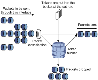
The evaluation for the traffic specification is based on whether the number of tokens in the bucket can meet the need of packet forwarding. If the number of tokens in the bucket is enough to forward the packets (generally, one token is associated with a 1-bit forwarding authority), the traffic conforms to the specification, and the traffic is called conforming traffic; otherwise, the traffic does not conform to the specification, and the traffic is called excess traffic.
A token bucket has the following configurable parameters:
l Mean rate: At which tokens are put into the bucket, namely, the permitted average rate of traffic. It is usually set to the committed information rate (CIR).
l Burst size: the capacity of the token bucket, namely, the maximum traffic size that is permitted in each burst. It is usually set to the committed burst size (CBS). The set burst size must be greater than the maximum packet size.
One evaluation is performed on each arriving packet. In each evaluation, if the number of tokens in the bucket is enough, the traffic conforms to the specification and the corresponding tokens for forwarding the packet are taken away; if the number of tokens in the bucket is not enough, it means that too many tokens have been used and the traffic is excessive.
The working mechanism of line rate
With line rate configured on an interface, all packets to be sent through the interface are firstly handled by the token bucket of line rate. If there are enough tokens in the token bucket, packets can be forwarded; otherwise, packets are put into QoS queues for congestion management. In this way, the traffic passing the physical interface is controlled.
Figure 2-3 Line rate implementation
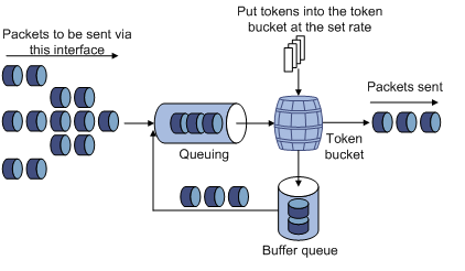
With a token bucket used for traffic control, when there are tokens in the token bucket, the bursty packets can be transmitted; if no tokens are available, packets cannot be transmitted until new tokens are generated in the token bucket. In this way, the traffic rate is restricted to the rate for generating tokens, thus limiting traffic rate and allowing bursty traffic.
QoS Policy
A QoS policy involves three components: class, traffic behavior, and policy. You can associate a class with a traffic behavior using a QoS policy.
Class
Classes are used to identify traffic.
A class is identified by a class name and contains some match criteria.
You can define a set of match criteria to classify packets. The relationship between criteria can be and or or.
l and: The device considers a packet belongs to a class only when the packet matches all the criteria in the class.
l or: The device considers a packet belongs to a class as long as the packet matches one of the criteria in the class.
Traffic behavior
A traffic behavior, identified by a name, defines a set of QoS actions for packets.
Policy
A policy associates a class with a traffic behavior.
You can define multiple class-to-traffic behavior associations in a policy.
Applying a QoS Policy
You can apply a QoS policy to a port. A QoS policy applied to a port applies to the inbound or outbound traffic of the port. A QoS policy can be applied to multiple ports. Only one policy can be applied in one direction (inbound or outbound) of a port.
Configuring QoS
QoS Configuration Task List
Configuring line rate
Perform the task in Table 2-1 to configure line rate on a port:
Table 2-1 Line rate configuration task list
|
Task |
Remarks |
|
Required Limit the rate of incoming packets or outgoing packets of a physical port. |
Configuring priority trust mode
Perform the task in Table 2-2 to configure priority trust mode:
Table 2-2 Priority trust mode configuration task list
|
Item |
Description |
|
Required Set the priority trust mode of a port. |
Configuring a QoS policy
Perform the tasks in Table 2-3 to configure a QoS policy:
Table 2-3 QoS policy configuration task list
|
Task |
Remarks |
|
|
Configure a class |
Required Create a class and specify the logical relationship between match criteria of the class. |
|
|
Required Configure match criteria for the class. |
||
|
Configure the traffic behavior |
Required Create a traffic behavior. |
|
|
Use either approach Configure various actions for the traffic behavior. |
||
|
Configure the policy |
Required Create a policy. |
|
|
Required Associate a traffic behavior with a class in the QoS policy. A class can be associated with only one traffic behavior in a QoS policy. If a class is associated with multiple traffic behaviors, the last associated one takes effect. |
||
|
Apply the policy |
Use either approach Apply the QoS policy to a VLAN or a port. |
|
Configuring Line Rate on a Port
Select QoS > Line rate in the navigation tree and click the Setup tab to enter the line rate configuration page, as shown in Figure 2-4.
Figure 2-4 The page for configuring line rate on a port

Table 2-4 describes the configuration items of configuring line rate on a port.
Table 2-4 Configuration items of configuring line rate on a port
|
Item |
Description |
|
Please select an interface type |
Select the types of interfaces to be configured with line rate. The interface types available for selection depend on your device model. |
|
Rate Limit |
Enable or disable line rate on the specified port. |
|
Direction |
Select a direction in which the line rate is to be applied. l Inbound: Limits the rate of packets received on the specified port. l Outbound: Limits the rate of packets sent by the specified port. Support for directions depends on your device model. |
|
CIR |
Set the committed information rate (CIR), the average traffic rate. |
|
CBS |
Set the committed burst size (CBS), number of bits that can be sent in each interval. |
|
EBS |
Set the excess burst size (EBS). |
|
Please select port(s) |
Specify the ports to be configured with line rate Click the ports to be configured with line rate in the port list. You can select one or more ports. |
Return to Line rate configuration task list.
Configuring Priority Trust Mode on a Port
Select QoS > Trust Mode in the navigation tree to enter the priority trust mode configuration page, as shown in Figure 2-5.
Figure 2-5 The page for configuring priority trust mode
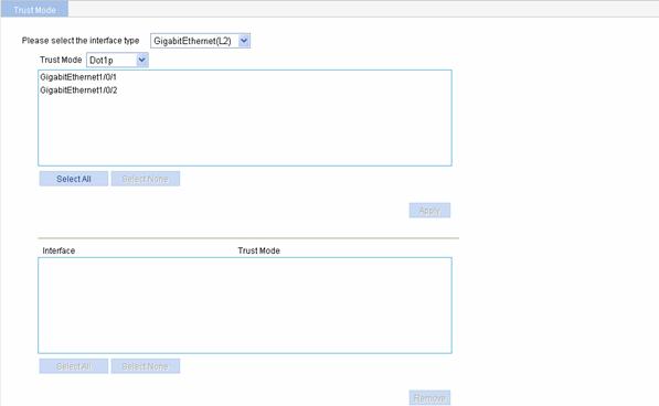
Table 2-5 describes the priority trust mode configuration items.
Table 2-5 Priority trust mode configuration items
|
Item |
Description |
|
Please select the interface type |
Select the type of the ports to be configured. The interface types available for selection depend on your device model. |
|
Trust Mode |
Select the priority trust mode. Which trust modes are supported depends on the interface type. |
|
(Select the ports) |
Specify the ports to be configured Click the ports to be configured in the port list. You can select one or more ports. |
Return to Priority trust mode configuration task list.
Creating a Class
Select QoS > Classifier in the navigation tree and click Create to enter the page for creating a class, as shown in Figure 2-6.
Figure 2-6 The page for creating a class
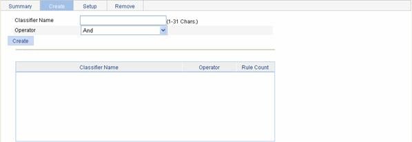
Table 2-6 shows the configuration items of creating a class.
Table 2-6 Configuration items of creating a class
|
Item |
Description |
|
Classifier Name |
Specify a name for the classifier to be created. Some devices have their own system-defined classifiers. The classifier name you specify cannot overlap with system-defined ones. The system-defined classifiers include: default-class, ef, af1, af2, af3, af4, ip-prec0, ip-prec1, ip-prec2, ip-prec3, ip-prec4, ip-prec5, ip-prec6, ip-prec7, mpls-exp0, mpls-exp1, mpls-exp2, mpls-exp3, mpls-exp4, mpls-exp5, mpls-exp6, and mpls-exp7. |
|
Operator |
Specify the logical relationship between rules of the classifier. l and: Specifies the relationship between the rules in a class as logic AND. That is, the device considers a packet belongs to a class only when the packet matches all the rules in the class. l or: Specifies the relationship between the rules in a class as logic OR. That is, the device considers a packet belongs to a class as long as the packet matches one of the rules in the class. |
Return to QoS policy configuration task list.
Configuring Classification Rules
Select QoS > Classifier in the navigation tree and click Setup to enter the page for setting a class, as shown in Figure 2-7.
Figure 2-7 The page for configuring classification rules
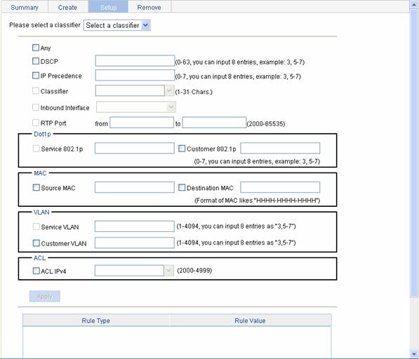
Table 2-7 shows the configuration items of configuring classification rules.
Table 2-7 Configuration items of configuring classification rules
|
Item |
Description |
|
|
Please select a classifier |
Select an existing classifier in the drop-down list. |
|
|
Any |
Define a rule to match all packets. Select the check box to match all packets. |
|
|
DSCP |
Define a rule to match DSCP values. If multiple such rules are configured for a class, the new configuration does not overwrite the previous one. You can configure up to eight DSCP values each time. If multiple identical DSCP values are specified, the system considers them as one. The relationship between different DSCP values is OR. After such configurations, all the DSCP values are arranged in ascending order automatically. |
|
|
IP Precedence |
Define a rule to match IP precedence values. If multiple such rules are configured for a class, the new configuration does not overwrite the previous one. You can configure up to eight IP precedence values each time. If multiple identical IP precedence values are specified, the system considers them as one. The relationship between different IP precedence values is OR. After such configurations, all the IP precedence values are arranged in ascending order automatically. |
|
|
Classifier |
Define a rule to match a QoS class. |
|
|
Inbound Interface |
Define a rule to match inbound interfaces |
|
|
RTP Port |
Define a rule to match a range of RTP ports Specify the start port in the from text box and the end port in the to textbox. This configuration item is not available currently. |
|
|
Dot1p |
Service 802.1p |
Define a rule to match the service 802.1p precedence values. If multiple such rules are configured for a class, the new configuration does not overwrite the previous one. You can configure up to eight Dot1p values each time. If multiple identical Dot1p values are specified, the system considers them as one. The relationship between different Dot1p values is OR. After such configurations, all the Dot1p values are arranged in ascending order automatically. |
|
Customer 802.1p |
Define a rule to match the customer 802.1p precedence values. If multiple such rules are configured for a class, the new configuration does not overwrite the previous one. You can configure up to eight Dot1p values each time. If multiple identical Dot1p values are specified, the system considers them as one. The relationship between different Dot1p values is OR. After such configurations, all the Dot1p values are arranged in ascending order automatically. |
|
|
MAC |
Source MAC |
Define a rule to match a source MAC address. If multiple such rules are configured for a class, the new configuration does not overwrite the previous one. A rule to match a source MAC address is significant only to Ethernet interfaces. |
|
Destination MAC |
Define a rule to match a destination MAC address. If multiple such rules are configured for a class, the new configuration does not overwrite the previous one. A rule to match a destination MAC address is significant only to Ethernet interfaces. |
|
|
VLAN |
Service VLAN |
Define a rule to match service VLAN IDs. If multiple such rules are configured for a class, the new configuration does not overwrite the previous one. You can configure multiple VLAN IDs each time. If the same VLAN ID is specified multiple times, the system considers them as one. The relationship between different VLAN IDs is logical OR. After such a configuration. You can specify VLAN IDs in two ways: l Enter a range of VLAN IDs, such as 10-500. The number of VLAN IDs in the range is not limited. l Specify a combination of individual VLAN IDs and VLAN ID ranges, such as 3, 5-7, 10. You can specify up to eight VLAN IDs in this way. |
|
Customer VLAN |
Define a rule to match customer VLAN IDs. If multiple such rules are configured for a class, the new configuration does not overwrite the previous one. You can configure multiple VLAN IDs each time. If the same VLAN ID is specified multiple times, the system considers them as one. The relationship between different VLAN IDs is logical OR. You can specify VLAN IDs in two ways: l Enter a range of VLAN IDs, such as 10-500. The number of VLAN IDs in the range is not limited. l Specify a combination of individual VLAN IDs and VLAN ID ranges, such as 3, 5-7, 10. You can specify up to eight VLAN IDs in this way. |
|
|
ACL |
ACL IPv4 |
Define an IPv4 ACL-based rule. The ACLs available for selection are existing IPv4 ACLs. |
Return to QoS policy configuration task list.
Creating a Traffic Behavior
Select QoS > Behavior in the navigation tree and click the Create tab to enter the page for creating a traffic behavior, as shown in Figure 2-8.
Figure 2-8 The page for creating a traffic behavior

Table 2-8 describes the configuration items of creating a behavior.
Table 2-8 Configuration items of creating a behavior
|
Item |
Description |
|
Behavior name |
Specify a name for the behavior to be created. Some devices have their own system-defined behaviors. The behavior name you specify cannot overlap with system-defined ones. The system-defined behaviors include ef, af, and be. |
Return to QoS policy configuration task list.
Configuring Actions for a Traffic Behavior
Select QoS > Behavior in the navigation tree and click Setup to enter the page for setting a traffic behavior, as shown in Figure 2-9.
Figure 2-9 The page for setting a traffic behavior
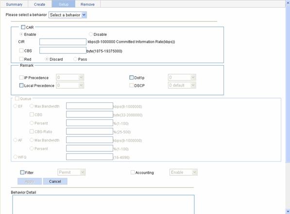
Table 2-9 describes the configuration items of configuring actions for a traffic behavior.
Table 2-9 Configuration items of configuring actions for a traffic behavior
|
Item |
Description |
||
|
Please select a behavior |
Select an existing behavior in the drop-down list. |
||
|
CAR |
Enable/Disable |
Enable or disable CAR |
|
|
CIR |
Set the committed information rate (CIR), the average traffic rate. |
||
|
CBS |
Set the committed burst size (CBS), number of bits that can be sent in each interval. |
||
|
Red |
Discard |
Set the action to perform for exceeding packets. After selecting the Red check box, you can select one of the following two options: l Discard: Drops the exceeding packet. l Pass: Permits the exceeding packet to pass through. |
|
|
Pass |
|||
|
Remark |
IP Precedence |
Configure the action of marking IP precedence for packets. Select the IP Precedence check box and then select the IP precedence value to be marked for packets in the following drop-down list. Select Not Set to cancel the action of marking IP precedence. |
|
|
Dot1p |
Configure the action of marking 802.1p precedence for packets. Select the Dot1p check box and then select the 802.1p precedence value to be marked for packets in the following drop-down list. Select Not Set to cancel the action of marking 802.1p precedence. |
||
|
Local Precedence |
Configure the action of marking local precedence for packets. Select the Local Precedence check box and then select the local precedence value to be marked for packets in the following drop-down list. Select Not Set to cancel the action of marking local precedence. |
||
|
DSCP |
Configure the action of marking DSCP precedence for packets. Select the DSCP check box and then select the DSCP precedence value to be marked for packets in the following drop-down list. Select Not Set to cancel the action of marking DSCP precedence. |
||
|
Queue |
EF |
Max Bandwidth |
Configure the maximum bandwidth for expedited forwarding (EF). |
|
CBS |
Configure the CBS for EF. |
||
|
Percent |
Configure the percent of available bandwidth for EF. |
||
|
CBS-Ratio |
Configure the ratio of CBS to CIR for EF. |
||
|
AF |
Min Bandwidth |
Configure the minimum guaranteed bandwidth for assured forwarding (AF). |
|
|
Percent |
Configure the percent of available bandwidth for AF. |
||
|
WFQ |
Configure WFQ for the default class by inputting the total number of fair queues, which must be the power of two. |
||
|
Filter |
Configure the packet filtering action. After selecting the Filter check box, select one item in the following drop-down list: l Permit: Forwards the packet. l Deny: Drops the packet. l Not Set: Cancels the packet filtering action. |
||
|
Accounting |
Configure the traffic accounting action. Select the Accounting check box and select Enable or Disable in the following drop-down list to enable/disable the traffic accounting action. |
||
Return to QoS policy configuration task list.
Creating a Policy
Select QoS > QoS Policy in the navigation tree and click Create to enter the page for creating a policy, as shown in Figure 2-10.
Figure 2-10 The page for creating a policy

Table 2-10 describes the configuration items of creating a policy.
Table 2-10 Configuration items of creating a policy
|
Item |
Description |
|
Policy Name |
Specify a name for the policy to be created. Some devices have their own system-defined policies. The policy name you specify cannot overlap with system-defined ones. The system-defined policy is the policy default. |
Return to QoS policy configuration task list.
Configuring Classifier-Behavior Associations for the Policy
Select QoS > QoS Policy in the navigation tree and click Setup to enter the page for setting a policy, as shown in Figure 2-11.
Figure 2-11 The page for setting a policy

Table 2-11 describes the configuration items of configuring classifier-behavior associations for the policy.
Table 2-11 Configuration items of configuring classifier-behavior associations for the policy
|
Item |
Description |
|
Please select a policy |
Select a created policy in the drop-down list. |
|
Classifier Name |
Select an existing classifier in the drop-down list. The classifiers available for selection are created on the page for creating a classifier. |
|
Behavior Name |
Select an existing behavior in the drop-down list. The behaviors available for selection are created on the page for creating a behavior. |
Return to QoS policy configuration task list.
Applying a Policy to a Port
Select QoS > Apply to Port in the navigation tree and click Setup to enter the page for applying a policy to a port, as shown in Figure 2-12.
Figure 2-12 The page for applying a policy to a port
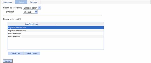
Table 2-12 describes the configuration items of applying a policy to a port.
Table 2-12 Configuration items of applying a policy to a port
|
Item |
Description |
|
Please select a policy |
Select a created policy in the drop-down list. |
|
Direction |
Set the direction in which the policy is to be applied. l Inbound: Applies the policy to the incoming packets of the specified ports. l Outbound: Applies the policy to the outgoing packets of the specified ports. |
|
Please select port(s) |
Click the ports to which the QoS policy is to be applied in the port list. You can select one or more ports. |
Return to QoS policy configuration task list.
Configuration Guidelines
When configuring QoS, note that:
1) When configuring line rate and traffic policing for a behavior, make sure that the ratio of CBS to CIR is more than 100:16. Otherwise, the handling for bursty traffic may be affected.
2) If an ACL is referenced by a QoS policy for defining traffic classification rules, the operation of the QoS policy varies by interface: The definition of software/hardware interface varies with device models. The specific process is as follows:
l If the QoS policy is applied to a software interface and the referenced ACL rule is a deny clause, the ACL rule does not take effect and packets go to the next classification rule.
l If the QoS policy is applied to a hardware interface, packets matching the referenced ACL rule are organized as a class and the behavior defined in the QoS policy applies to the class regardless of whether the referenced ACL rule is a deny or permit clause.
3) If a QoS policy is applied in the outbound direction of a port, the QoS policy cannot influence local packets. Local packets refer to the important protocol packets that maintain the normal operation of the device. QoS must not process such packets to avoid packet drop. Commonly used local packets are: link maintenance packets, ISIS packets, OSPF packets, RIP packets, BGP packets, LDP packets, RSVP packets, and SSH packets and so on.
4) When configuring queuing for a traffic behavior:
l In a policy, a traffic behavior with EF configured cannot be associated with the default class, while a traffic behavior with WFQ configured can only be associated with the default class.
l In a policy, the total bandwidth assigned to the AF and EF classes cannot be greater than the available bandwidth of the interface to which the policy applies; the total bandwidth percentage assigned to the AF and EF classes cannot be greater than 100%.
l In the same policy, the same bandwidth unit must be used to configure bandwidth for AF classes and EF classes, either absolute bandwidth value or percent.
Overview
An 802.11 network offers contention-based wireless access. To provide applications with QoS services, IEEE developed 802.11e for the 802.11-based WLAN architecture.
While IEEE 802.11e was being standardized, Wi-Fi Alliance defined the Wi-Fi Multimedia (WMM) standard to allow QoS provision devices of different vendors to interoperate. WMM makes a WLAN network capable of providing QoS services.
Terminology
1) WMM
WMM is a wireless QoS protocol designed to preferentially transmit packets with high priority, thus guaranteeing better QoS services for voice and video applications in a wireless network.
2) EDCA
Enhanced distributed channel access (EDCA) is a channel contention mechanism designed by WMM to preferentially transmit packets with high priority and allocate more bandwidth to such packets.
3) AC
Access category (AC), is used for channel contention. WMM defines four access categories; they are AC-VO (voice), AC-VI (video), AC-BE (best-effort), and AC-BK (background) in the descending order of priority. When contending for a channel, a high-priority AC preempts a low-priority AC.
4) CAC
Connection admission control (CAC) limits the number of clients that are using high-priority ACs (AC-VO and AC-VI) to guarantee sufficient bandwidth for existing high-priority traffic.
5) U-APSD
Unscheduled automatic power-save delivery (U-APSD) is a new power saving mechanism defined by WMM to enhance the power saving capability of clients.
6) SVP
SpectraLink voice priority (SVP) is a voice priority protocol designed by the Spectralink company to guarantee QoS for voice traffic.
WMM Protocol Overview
The distributed coordination function (DCF) in 802.11 stipulates that access points (APs) and clients use the carrier sense multiple access with collision avoidance (CSMA/CA) access mechanism. APs or clients listen to the channel before they hold the channel for data transmission. When the specified idle duration of the channel times out, APs or clients randomly select a backoff slot within the contention window to perform backoff. The device that finishes backoff first gets the channel. With 802.11, all devices have the same idle duration and contention window. Therefore, they are equal when contending for a channel. In WMM, this fair contention mechanism is changed.
EDCA parameters
WMM assigns data packets in a basic service set (BSS) to four ACs. By allowing a high-priority AC to have more channel contention opportunities than a low-priority AC, WMM offers different service levels to different ACs.
WMM define a set of EDCA parameters for each AC, covering the following:
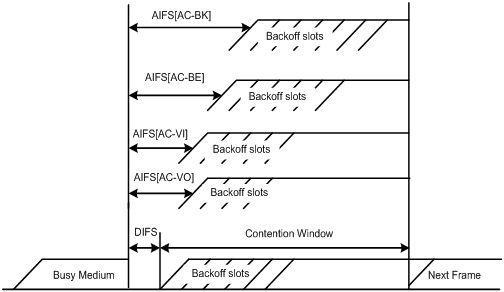
l Arbitration inter-frame spacing number (AIFSN): Different from the 802.11 protocol where the idle duration (set using DIFS) is a constant value, WMM can define an idle duration per AC. The idle duration increases as the AIFSN value increases (see Figure 3-1 for the AIFS durations).
l Exponent form of CWmin (ECWmin) and exponent form of CWmax (ECWmax) determine the average backoff slots, which increases as the two values increase (see Figure 3-1 for the backoff slots).
l Transmission opportunity limit (TXOPLimit) indicates the maximum time for which a user can hold a channel after a successful contention. The greater the TXOPLimit is, the longer the user can hold the channel. The value 0 indicates that the user can send only one packet each time it holds the channel.
Figure 3-1 Per-AC channel contention parameters in WMM
CAC admission policies
CAC requires that a client obtain permission of the AP before it can use a high-priority AC for transmission, thus guaranteeing bandwidth to the clients that have gained access. CAC controls real time traffic (AC-VO and AC-VI traffic) but not common data traffic (AC-BE and AC-BK traffic).
If a client wants to use a high-priority AC, it needs to send a request to the AP. The AP returns a positive or negative response based on either of the following admission control policy:
l Channel utilization-based admission policy: the AP calculates the total time that the existing high-priority ACs occupies the channel in one second, and then calculates the time that the requesting traffic will occupy the channel in one second. If the sum of the two values is smaller than or equal to the maximum hold time of the channel, the client can use the requested AC. Otherwise, the request is rejected.
l Users-based admission policy: if the number of clients using high-priority ACs plus the requesting clients is smaller than or equal to the maximum number of high-priority AC clients, the request is accepted. Otherwise, the request is rejected. During calculation, a client is counted once even if it is using both AC-VO and AC-VI.
U-APSD power-save mechanism
U-APSD improves the 802.11 APSD power saving mechanism. When associating clients with ACs, you can specify some ACs as trigger-enabled, some ACs as delivery-enabled, and the maximum number of data packets that can be delivered after receiving a trigger packet. Both the trigger attribute and the delivery attribute can be modified when flows are established using CAC. When a client sleeps, the delivery-enabled AC packets destined for the client are buffered. The client needs to send a trigger-enabled AC packet to get the buffered packets. After the AP receives the trigger packet, packets in the transmit queue are sent. The number of sent packets depends on the agreement made when the client was admitted. ACs without the delivery attribute store and transmit packets as defined in the 802.11 protocol.
SVP
SVP can assign packets with the protocol ID 119 in the IP header to a specific AC. SVP stipulates that random backoff is not performed for SVP packets. Therefore, you can set both ECWmin and ECWmax to 0 when there are only SVP packets in an AC.
ACK policy
WMM defines two ACK policies: Normal ACK and No ACK.
l When the no acknowledgement (No ACK) policy is used, the recipient does not acknowledge received packets during wireless packet exchange. This policy is suitable in the environment where communication quality is fine and interference is weak. While the No ACK policy helps improve transmission efficiency, it can cause increased packet loss when communication quality deteriorates. This is because when this policy is used, a sender does not retransmit packets that have not been received by the recipient.
l When the Normal ACK policy is used, the recipient acknowledges each received unicast packet.
Configuring Wireless QoS
Setting SVP Mapping
Select QoS > Wireless QoS from the navigation tree, and then select Wireless QoS to enter the page for displaying wireless QoS, as shown in Figure 3-2.
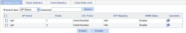
Find the desired AP in the AP list, and
click the ![]() icon
in the Operation column to enter the page for setting SVP mapping, as
shown in Figure 3-3.
icon
in the Operation column to enter the page for setting SVP mapping, as
shown in Figure 3-3.
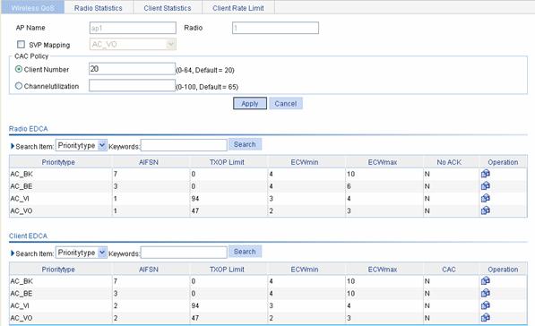
Table 3-1 shows the configuration items of setting SVP mapping.
Table 3-1 Configuration items of setting SVP mapping
|
Item |
Description |
|
AP Name |
Displays the selected AP |
|
Radio |
Displays the selected AP’s radio |
|
SVP Mapping |
Select the check box before SVP Mapping, and then select the AC priority queue to be used by the SVP service: l AC-VO l AC-VI l AC-BE l AC-BK |
Setting CAC Admission Policy
Select QoS > Wireless QoS
from the navigation tree, select the Wireless QoS tab, and find the
desired AP in the AP list, and click the corresponding ![]() icon in the Operation column
to enter the page for setting CAC admission policy, as shown in Figure 3-3.
icon in the Operation column
to enter the page for setting CAC admission policy, as shown in Figure 3-3.
Table 3-2 shows the configuration items of setting CAC admission policy.
Table 3-2 Configuration items of setting CAC admission policy
|
Item |
Description |
|
Client Number |
Users-based admission policy, namely, maximum number of clients allowed to be connected. A client is counted only once, even if it is using both AC-VO and AC-VI. By default, the users-based admission policy applies, with the maximum number of users being 20. |
|
Channel Utilization |
Channel utilization-based admission policy, namely, the rate of the medium time of the accepted AC-VO and AC-VI traffic to the valid time during the unit time. The valid time is the total time during which data is transmitted. |
Setting Radio EDCA Parameters
Select QoS > Wireless QoS from the navigation tree, select the Wireless QoS tab, and find the desired AP in the AP list, and click the corresponding icon in the Operation column to enter the page for setting radio EDCA parameters. In the Radio EDCA list, find the priority type (AC-BK priority is taken as an example here) to be modified, and click the corresponding icon in the Operation column to enter the page for setting radio EDCA parameters.
Figure 3-4 Set radio EDCA parameters
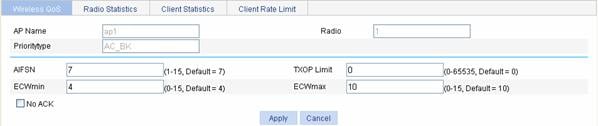
Table 3-3 shows the configuration items of setting radio EDCA parameters.
Table 3-3 Configuration items of setting AP EDCA
|
Item |
Description |
|
AP Name |
Displays the selected AP |
|
Radio |
Displays the selected AP’s radio |
|
Priority type |
Displays the priority type |
|
AIFSN |
Arbitration inter-frame spacing number |
|
TXOP Limit |
Transmission opportunity limit |
|
ECWmin |
Exponent form of CWmin, namely, minimum ECWmin allowed by the radio chip |
|
ECWmax |
Exponent form of CWmax, namely, maximum ECWmin allowed by the radio chip |
|
No ACK |
If you select the checkbox before No ACK, the No ACK policy is adopted. By default, the normal ACK policy is adopted. |
Table 3-4 shows the default EDCA parameters.
Table 3-4 Default radio EDCA parameters
|
AC |
AIFSN |
ECWmin |
ECWmax |
|
|
AC-BK |
7 |
4 |
10 |
0 |
|
AC-BE |
3 |
4 |
6 |
0 |
|
AC-VI |
1 |
3 |
4 |
94 |
|
AC-VO |
1 |
2 |
3 |
47 |
l ECWmin cannot be bigger than ECWmax.
l When the AP works in 802.11b radio mode, you are recommended to set the TXOP-Limit of AC-BK, AC-BE, AC-VI, and AC-VO to 0, 0, 188, and 102 respectively.
Setting Client EDCA Parameters
Select QoS > Wireless QoS from the navigation tree, select the Wireless QoS tab, and find the desired AP in the AP list, and click the corresponding icon in the Operation column to enter the page for setting wireless QoS. In the Client EDCA list, find the priority type (AC-BK priority is taken as an example here) to be modified, and click the corresponding icon in the Operation column to enter the page for setting client EDCA parameters.
Figure 3-5 Set client EDCA parameters
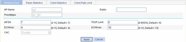
Table 3-5 shows the configuration items of setting client EDCA parameters.
Table 3-5 Configuration items of setting client EDCA
|
Item |
Description |
|
AP Name |
Displays the selected AP |
|
Radio |
Displays the selected AP’s radio |
|
Priority type |
Displays the priority type |
|
AIFSN |
Arbitration inter-frame spacing number |
|
TXOP Limit |
Transmission opportunity limit |
|
ECWmin |
Exponent form of CWmin, namely, minimum ECWmin allowed by the radio chip |
|
ECWmax |
Exponent form of CWmax, namely, maximum ECWmin allowed by the radio chip |
|
CAC |
Enables CAC. AC-VO and AC-VI support CAC, which is disabled by default. AC-BE and AC-BK do not support CAC. l Enable: Enables CAC. l Disable: Disables CAC. |
Table 3-6 shows the default client EDCA parameters.
Table 3-6 Default EDCA parameters for clients
|
AC |
AIFSN |
ECWmin |
ECWmax |
TXOP Limit |
|
AC-BK |
7 |
4 |
10 |
0 |
|
AC-BE |
3 |
4 |
10 |
0 |
|
AC-VI |
2 |
3 |
4 |
94 |
|
AC-VO |
2 |
2 |
3 |
47 |
![]()
l ECWmin cannot be bigger than ECWmax.
l If all clients work in 802.11b radio mode, you are recommended to set TXOP-Limit to 188 and 102 for AC-VI and AC-VO.
l If both clients using 802.11b radio cards and clients using 802.11g radio cards exist in the network, you can recommended to set TXOP-Limit as shown in Table 3-6.
l If CAC is enabled for a priority queue, CAC is also enabled for higher-priority queues. For example, if you enable CAC for AC-VI, CAC is also enabled for AC-VO. However, enabling CAC for AC-VO does not enable CAC for AC-VI.
Displaying Radio Information
Select QoS > Wireless QoS from the navigation tree, select the Radio Information tab, and enter the page for displaying the radio information. Click an AP to see the detailed information about it.
Table 3-7 Description on the output radio information
|
Field |
Description |
|
AP ID |
AP ID |
|
AP Name |
AP name |
|
Radio |
Radio ID |
|
Client EDCA update count |
The times of updating EDCA parameters |
|
QoS mode |
QoS mode: l WMM: enable QoS l None: disable QoS |
|
Radio chip QoS mode |
Radio’s support for QoS |
|
Radio chip max AIFSN |
The maximum AIFSN value supported by the radio |
|
Radio chip max ECWmin |
The maximum ECWmin value supported by the radio |
|
Radio chip max TXOPLimit |
The maximum TXOPLimit value supported by the radio |
|
Radio chip max ECWmax |
The maximum ECWmax supported by the radio |
|
Client accepted |
Number of clients allowed to access the radio, including the number of clients in the voice queue and the number of clients in the video queue |
|
Total request mediumtime(us) |
The request time of all queues, including that of the voice queue and that of the video queue |
|
Calls rejected due to insufficient resource |
Number of calls rejected due to insufficient resources |
|
Calls rejected due to invalid parameters |
Number of calls rejected due to invalid parameters |
|
Calls rejected due to invalid mediumtime |
Number of calls rejected due to invalid mediumtime |
|
Calls rejected due to invalid delaybound |
Number of calls rejected due to invalid delaybound |
Displaying Client Information
Select QoS > Wireless QoS from the navigation tree, select the Client Information tab, and enter the page for displaying the client information. Click a client to see the detailed information about it.
Table 3-8 Description on the output client information
|
Field |
Description |
|
MAC address |
MAC address of the client |
|
SSID |
SSID name |
|
QoS Mode |
QoS mode: l WMM: enable QoS l None: disable QoS |
|
Max SP length |
Maximum service time |
|
AC |
Access class |
|
State |
APSD attribute of an AC queue l T: trigger-enabled l D: delivery-enabled l T | D: both trigger-enabled and delivery-enabled l L: Legacy |
|
Assoc State |
APSD attribute of the specified AC when the client accesses |
|
Uplink CAC packets |
Number of uplink CAC packets |
|
Uplink CAC bytes |
Number of uplink CAC bytes |
|
Downlink CAC packets |
Number of downlink CAC packets |
|
Downlink CAC bytes |
Number of downlink CAC bytes |
|
Downgrade packets |
Number of downgraded packets |
|
Downgrade bytes |
Number of downgraded bytes |
|
Discard packets |
Number of dropped packets |
|
Discard bytes |
Number of dropped bytes |
Setting Rate Limiting
To ensure that all clients in a WLAN can use the network services normally, you need to configure rate limiting for clients in the WLAN. You can perform client-based rate limiting in one of the following two modes:
l Dynamic mode: Allows you to configure the total rate of all clients associated with the same AP. The rate limit of a client is the configured total rate/the number of clients. For example, if the configure total rate is 10 Mbps and five clients are online, the rate of each client is 2 Mbps.
l Static mode: Allows you to configure a rate limit for each client associated with the same AP. That is, each client of the AP cannot exceed the rate limit. For example, if the configured rate is 1 Mbps, the rate limit of each user online is 1 Mbps.
Select QoS > Wireless QoS > Rate Limiting from the navigation tree, find the wireless service to be configured, and click the corresponding icon in the Operation column to enter the page for setting rate limiting, as shown in Figure 3-6.

Table 3-9 shows the configuration items of setting rate limiting.
Table 3-9 Configuration items of setting rate limiting
|
Item |
Description |
|
Wireless Service |
Displays an existing wireless service |
|
Direction |
Inbound or outbound l Inbound: from clients to the AP l Outbound: from the AP to clients |
|
Mode |
Rate limiting mode, dynamic or static l Dynamic mode: configures the total rate of all clients associated with the same AP. The rate limit of a client is the configured total rate/the number of clients. l Static mode: configures the rate limit for each client. |
|
Rate |
Sets the rate of the clients l If you select the dynamic mode, the rate is the total rate of all clients. l If you select the static mode, the rate is the rate of each client. |
ACL/QoS Configuration Example
Network requirements
As shown in Figure 4-1, in the WLAN, the AC connects to the FTP server (whose IP address is 10.1.1.1/24), and the wireless clients connect to the AC through WLAN-ESS 1.
Configure an ACL and a QoS policy as follows to prohibit the hosts from accessing the FTP server from 8:00 to 18:00 every day.
1) Create an ACL to prohibit the hosts from accessing the FTP server from 8:00 to 18:00 every day.
2) Configure a QoS policy to drop the packets matching the ACL.
3) Apply the QoS policy in the inbound direction of WLAN-ESS 1.
Figure 4-1 Network diagram for ACL/QoS configuration
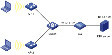
Configuration procedure
1) Configure the time range
# Define a time range to cover the time range from 8:00 to 18:00 every day.
l Select QoS > Time Range in the navigation tree and click Create.
l Type the time range name test-time.
l Select the Periodic Time Range check box, set the Start Time to 8:00 and the End Time to 18:00, and then select the checkboxes Sun through Sat.
l Click Apply to complete the operation.
2) Define an IPv4 ACL for traffic to the FTP server.
# Create an advanced IPv4 ACL.
l Select QoS > ACL IPv4 in the navigation tree and click Create.
l Type the ACL number 3000.
l Click Apply to complete the operation.
# Define an ACL rule for traffic from the other departments to the FTP server.
l Click Advance Setup.
l Select ACL 3000 in the drop-down list.
l Select the Rule ID check box, and type rule ID 2.
l Select Deny in the Operation drop-down list.
l Select the Destination IP Address check box, and type IP address 10.1.1.1 and destination wildcard 0.0.0.0.
l Select test-time in the Time Range drop-down list.
l Click Add to complete the operation.
3) Configure a QoS policy
# Create a class.
l Select QoS > Classifier in the navigation tree and click Create.
l Type the class name class1.
l Click Create to complete the operation.
# Define classification rules.
l Click Setup.
l Select the class name class1 in the drop-down list.
l Select the ACL IPv4 check box, and select ACL 3000 in the following drop-down list.
l Click Apply to complete the operation.
# Create a traffic behavior.
l Select QoS > Behavior in the navigation tree and click Create.
l Type the behavior name behavior1.
l Click Create to complete the operation.
# Configure actions for the traffic behavior.
l Click Setup.
l Select behavior1 in the drop-down list.
l Select the Filter check box, and then select Permit in the following drop-down list.
l Click Apply to complete the operation.
# Create a policy.
l Select QoS > QoS Policy in the navigation tree and click the Create tab.
l Type the policy name policy1.
l Click Create to complete the operation.
# Configure classifier-behavior associations for the policy.
l Click Setup.
l Select policy1.
l Select class1 in the Classifier Name drop-down list.
l Select behavior1 in the Behavior Name drop-down list.
l Click Apply to complete the operation.
# Apply the QoS policy in the inbound direction of GigabitEthernet 1/0/1.
l Select QoS > Apply to Port in the navigation tree and click the Setup tab.
l Select policy1 in the Please select a policy drop-down list.
l Select Inbound in the Direction drop-down list.
l Select port WLAN-ESS1.
l Click Apply to complete the operation.