- Table of Contents
-
- H3C WX Series Access Controllers Web-Based Configuration Manual-6PW103
- 00-1Cover
- 01-Quick Start
- 02-Web Overview
- 03-Summary
- 04-Device
- 05-Network
- 06-AP Configuration
- 07-WLAN Service Configuration
- 08-WLAN Roaming Configuration
- 09-Radio Configuration
- 10-Authentication
- 11-Security
- 12-QoS
- 13-SNMP
- 14-Advanced Settings
- Related Documents
-
| Title | Size | Download |
|---|---|---|
| 05-Network | 600.45 KB |
Table of Contents
Configuring a MAC Address Entry
Setting the Aging Time of MAC Address Entries
Introduction to Port-Based VLAN
Introduction to DHCP Relay Agent
Enabling the DHCP Server on an Interface
Configuring a Static Address Pool for the DHCP Server
Configuring a Dynamic Address Pool for the DHCP Server
Configuring a DHCP Server Group
Enabling the DHCP Relay Agent on an Interface
Dynamic Domain Name Resolution
Configuring Static Name Resolution Table
Configuring Dynamic Domain Name Resolution
Configuring DNS Server Addresses
Configuring Domain Name Suffixes
7 IPv4 and IPv6 Routing Configuration
Displaying the IPv4 Active Route Table
Displaying the IPv6 Active Route Table
Static Route Configuration Examples
IPv4 Static Route Configuration Example
IPv6 Static Route Configuration Example
Configuring Service Management
l The sample Web page information in this manual was created on the WX5002. The Web page information on your device may vary.
l The models listed in this manual are not applicable to all regions. Please consult the local agents for the models applicable to your region.
The following table shows the support of the H3C WX series access controller products for features:
|
Feature |
WX5000 series |
WX6000 series |
WX3000 series |
||||||
|
WX5002 |
LS8M1WCMA0 |
WX5004 |
WX6103 |
LSQM1WCMB0 |
LSBM1WCM2A0 |
WX3024 |
WX3010 |
WX3008 |
|
|
IPv6 |
Supported |
Supported |
Supported |
Supported |
Supported |
Not supported |
Not supported |
Not supported |
Not supported |
![]()
l Currently, MAC address configurations relevant to interfaces only apply to Layer 2 Ethernet interfaces.
l This manual covers only the management of static and dynamic MAC address entries. The multicast MAC address entries management is not introduced here.
Overview
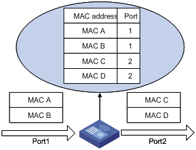
A device maintains a MAC address table for frame forwarding. Each entry in this table includes the MAC address of a connected device, to which interface this device is connected and to which VLAN the interface belongs. A MAC address table consists of two types of entries: static and dynamic. Static entries are manually configured and never age out. Dynamic entries can be manually configured or dynamically learned and will age out.
The following is how your device learns a MAC address after it receives a frame from a port, port A for example:
1) Checks the frame for the source MAC address (MAC-SOURCE for example).
2) Looks up the MAC address table for an entry corresponding to the MAC address and do the following:
l If an entry is found for the MAC address, updates the entry.
l If no entry containing the MAC address is found, adds an entry that contains the MAC address and the receiving port (port A) to the MAC address table.
After the MAC address (MAC-SOURCE) is learned, if the device receives a frame destined for MAC-SOURCE, the device looks up the MAC address table and then forwards the frame from port A.
![]()
Dynamically learned MAC addresses cannot overwrite static MAC address entries, but the latter can overwrite the former.
When forwarding a frame, the device adopts the following two forwarding modes based on the MAC address table:
l Unicast mode: If an entry matching the destination MAC address exists, the device forwards the frame directly from the sending port recorded in the entry.
l Broadcast mode: If the device receives a frame with the destination address being all Fs, or no entry matches the destination MAC address, the device broadcasts the frame to all the ports except the receiving ports.
Figure 1-1 MAC address table of the device
Configuring MAC Addresses
MAC addresses configuration includes the configuring and displaying of MAC address entries, and the setting of MAC address entry aging time.
Configuring a MAC Address Entry
Select Network > MAC from the navigation tree. The system automatically displays the MAC tab, which shows all the MAC address entries on the device, as shown in Figure 1-2. Click Add in the bottom to enter the page for creating MAC address entries.
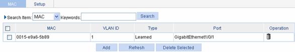
Table 1-1 shows the detailed configuration for creating a MAC address entry.
Table 1-1 Configuration items for creating a MAC address entry
|
Item |
Description |
|
MAC |
Sets the MAC address to be added |
|
Type |
Sets the type of the MAC address entry, which can be: l static: indicates static MAC address entries that never age out l dynamic: indicates dynamic MAC address entries that will age out l blackhole: indicates blackhole MAC address entries that never age out
The types of the MAC address entries displayed in the tab are as follows: l Config static: indicates static MAC address entries manually configured by the users l Config dynamic: indicates dynamic MAC address entries manually configured by the users l Blackhole: indicates blackhole MAC address entries l Learned: indicates dynamic MAC address entries learned by the device l Other: indicates types other than the ones mentioned above |
|
VLAN |
Sets the ID of the VLAN to which the MAC address belongs |
|
Port |
Sets the port to which the MAC address belongs. This configuration item is not required for a blackhole entry. |
Setting the Aging Time of MAC Address Entries
Select Network > MAC from the navigation tree, and then select the Config tab to enter the page for setting the MAC address entry aging time, as shown in Figure 1-3.
Figure 1-3 The page for setting the aging time for MAC address entries
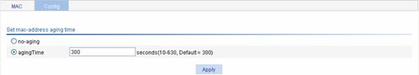
The following table shows the detailed configuration of setting the MAC address entry aging time.
Table 1-2 Configuration items of setting the aging time for a MAC address entry
|
Item |
Description |
|
No-aging |
Specifies that the MAC address entry never ages out. |
|
Aging time |
Types the aging time for the MAC address entry |
Configuration Example
Network requirements
Use the MAC address table management function through the Web network management. It is required to add a static MAC address 00e0-fc35-dc71 under port GigabitEthernet 1/0/1 in VLAN 1.
Configuration procedure
# Create a static MAC address entry.
l Select Network > MAC from the navigation tree to enter the MAC tab page, and then click Add.
l Type MAC address 00e0-fc35-dc71.
l Select static in the Type drop down list.
l Select 1 in the VLAN ID drop down list.
l Select GigabitEthernet 1/0/1 in the Port drop down list.
l Click Apply to complete the operation.
Overview
Introduction to VLAN
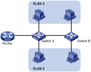
Ethernet is a network technology based on the Carrier Sense Multiple Access/Collision Detect (CSMA/CD) mechanism. As the medium is shared, collisions and excessive broadcasts are common on an Ethernet. To address the issue, virtual LAN (VLAN) was introduced. The idea is to break a LAN down into separate VLANs, that is, Layer 2 broadcast domains whereby frames are switched between ports assigned to the same VLAN. VLANs are isolated from each other at Layer 2. A VLAN is a bridging domain, and all broadcast traffic is contained within it, as shown in Figure 2-1.
A VLAN is logically divided on an organizational basis rather than on a physical basis. For example, all workstations and servers used by a particular workgroup can be connected to the same LAN, regardless of their physical locations.
VLAN technology delivers the following benefits:
l Confining broadcast traffic within individual VLANs. This reduces bandwidth waste and improves network performance.
l Improving LAN security. By assigning user groups to different VLANs, you can isolate them at Layer 2. For hosts in different VLANs to communicate, routers or Layer 3 switches are required.
l Flexible virtual workgroup creation. As users from the same workgroup can be assigned to the same VLAN regardless of their physical locations, network construction and maintenance is much easier and more flexible.
VLAN Fundamentals
To enable a network device to identify frames of different VLANs, a VLAN tag field is inserted into the data link layer encapsulation.
The format of VLAN-tagged frames is defined in IEEE 802.1Q-1999.
In the header of a traditional Ethernet data frame as shown in Figure 2-2, the field after the destination MAC address and the source MAC address fields (DA&SA in the figure) is the Type field indicating the upper layer protocol type.
Figure 2-2 The format of a traditional Ethernet frame
![]()
IEEE 802.1Q inserts a four-byte VLAN tag before the Type field, as shown in Figure 2-3.
Figure 2-3 The position and format of VLAN tag
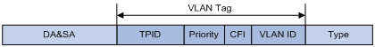
A VLAN tag comprises four fields: tag protocol identifier (TPID), priority, canonical format indicator (CFI), and VLAN ID.
l The 16-bit TPID field with a value of 0x8100 indicates that the frame is VLAN tagged.
l The 3-bit priority field indicates the 802.1p priority of the frame.
l The 1-bit CFI field specifies whether the MAC addresses are encapsulated in the canonical format for the receiving device to correctly interpret the MAC addresses. Value 0 indicates that the MAC addresses are encapsulated in canonical format; value 1 indicates that the MAC addresses are encapsulated in non-canonical format. The field is set to 0 by default.
l The 12-bit VLAN ID field identifies the VLAN the frame belongs to. The VLAN ID range is 0 to 4095. As 0 and 4095 are reserved by the protocol, the VLAN ID range available for assignment is 1 to 4094.
When receiving a frame, a network device looks at its VLAN tag to decide how to handle the frame.
![]()
The Ethernet II encapsulation format is used in this section. Besides this format, other encapsulation formats, including 802.2 LLC, 802.2 SNAP, and 802.3 raw, are also supported by Ethernet. The VLAN tag fields are also used in these encapsulations for VLAN identification.
Types of VLAN
You can create VLANs based on:
l Port
l MAC address
l Protocol
l IP subnet
l Policy
l Other criteria
Introduction to Port-Based VLAN
Port-based VLANs group VLAN members by port. A port forwards traffic for a VLAN only after it is assigned to the VLAN.
Port link type
Depending on the tag handling mode, the link type of a port can be one of the following three:
l Access. An access port belongs to only one VLAN and usually connects to a user device.
l Trunk. A trunk port can join multiple VLANs to receive and send traffic for them. It usually connects to a network device.
l Hybrid. A hybrid port can join multiple VLANs to receive and send traffic for them. It can connect either a user device or a network device.
A hybrid port is different from a trunk port in that:
l A hybrid port allows traffic of multiple VLANs to pass through untagged.
l A trunk port allows only traffic of the default VLAN to pass through untagged.
Default VLAN (PVID)
By default, VLAN 1 is the default VLAN for all ports. However, you can change the default VLAN for a port as required. When doing that, follow these guidelines:
l Because an access port can join only one VLAN, its default VLAN is the VLAN to which it belongs and cannot be configured.
l Because a trunk or hybrid port can join multiple VLANs, you can configure a default VLAN for the port.
A port configured with a default VLAN handles a frame as follows:
|
Port type |
Actions (in the inbound direction) |
Actions (in the outbound direction) |
|
|
Untagged frame |
Tagged frame |
||
|
Access |
Tag the frame with the default VLAN tag. |
l Receive the frame if its VLAN ID is the same as the default VLAN ID. l Drop the frame if its VLAN ID is different from the default VLAN ID. |
Remove the default VLAN tag and send the frame. |
|
Trunk |
Check whether the default VLAN is carried on the port: l If yes, tag the frame with the default VLAN tag. l If not, drop the frame. |
l Receive the frame if its VLAN is carried on the port. l Drop the frame if its VLAN is not carried on the port. |
l Remove the tag and send the frame if the frame carries the default VLAN tag. l Send the frame without removing the tag if its VLAN is carried on the port but is different from the default one. |
|
Hybrid |
Send the frame if its VLAN is carried on the port. The frame is sent with the VLAN tag removed or intact depending on your configuration. |
||
Configuring a VLAN
Configuration Task List
Perform the tasks in Table 2-1 to configure a VLAN:
Table 2-1 VLAN configuration task list
|
Task |
Remarks |
|
Required |
|
|
Required Select either task Configure the untagged member ports and tagged member ports of the VLAN, or remove ports from the VLAN. |
|
Creating a VLAN
Select Network > VLAN in the navigation tree. The system automatically selects the VLAN tab and enters the page as shown in Figure 2-4.
Figure 2-4 VLAN configuration page
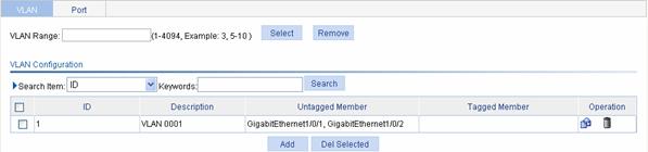
Click Add to enter the page for creating a VLAN.
Table 2-2 describes the configuration items of creating a VLAN.
Table 2-2 Configuration items of creating a VLAN
|
Item |
Description |
|
VLAN ID |
ID of the VLAN to be created |
Return to VLAN configuration task list.
Modifying a VLAN
Select Network > VLAN in
the navigation tree. The system automatically selects the VLAN tab and
enters the page as shown in Figure
2-4. In the Operation column for the VLAN you want to modify,
click the ![]() icon
to enter the page for modifying the VLAN.
icon
to enter the page for modifying the VLAN.
Table 2-3 describes the configuration items of modifying a VLAN.
Table 2-3 Configuration items of configuring the ports in a VLAN
|
Item |
Description |
|
|
ID |
Displays the ID of the VLAN to be modified |
|
|
Description |
Set the description string of the VLAN By default, the description string of a VLAN is its VLAN ID, such as VLAN 0001. |
|
|
Port |
Untagged Member |
Set the member type of the port to be modified in the VLAN Find the port to be modified and select the Untagged Member, Tagged Member, or Not A Member option for the port: l Untagged: Indicates that the port sends the traffic of the VLAN with the VLAN tag removed. l Tagged: Indicates that the port sends the traffic of the VLAN without removing the VLAN tag. l Not a Member: Removes the port from the VLAN.
For VLAN 1, no port list is displayed and you can only modify the description string. |
|
Tagged Member |
||
|
Not A Member |
||
Return to VLAN configuration task list.
Modifying a Port
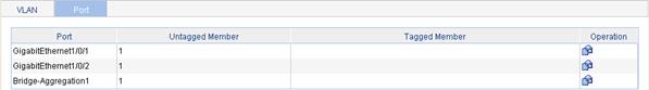
Select Network > VLAN in the navigation tree, and select the Port tab to enter the page as shown in Figure 2-5.
Figure 2-5 Port configuration page
In the Operation column, click the ![]() icon for the
port to be modified to enter the page for modifying the port.
icon for the
port to be modified to enter the page for modifying the port.
Table 2-4 describes the configuration items of modifying a port.
Table 2-4 Configuration items of modifying a port
|
Item |
Description |
|
|
Port |
Display the port to be modified |
|
|
Untagged Member VLAN |
Display the VLAN(s) to which the port belongs as an untagged member |
|
|
Tagged Member VLAN |
Display the VLAN(s) to which the port belongs as a tagged member |
|
|
Member Type |
Untagged |
Set the target member type of the port Select the Untagged, Tagged, or Not A Member radio button: l Untagged: Indicates that the port sends the traffic of the VLAN with the VLAN tag removed. l Untagged: Indicates that the port sends the traffic of the VLAN without removing the VLAN tag. l Not A Member: Removes the port from the VLAN. |
|
Tagged |
||
|
Not A Member |
||
|
VLAN ID |
Specify the VLAN to which the port belongs. |
|
Return to VLAN configuration task list.
VLAN Configuration Example
![]()
For WX6103 or WX3024 devices, internal GE ports are used in configuration examples similar to the one described here. Internal GE port numbering varies with devices. The configuration example below was created on the WX5002. The actual configuration procedure on your device may vary.
Network requirements
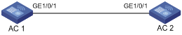
l GigabitEthernet 1/0/1 of AC 1 is connected to GigabitEthernet 1/0/1 of AC 2.
l GigabitEthernet 1/0/1 of AC 1 and AC 2 are trunk ports with VLAN 100 as their default VLAN.
l Configure both ports to permit packets of VLAN 2, VLAN 6 through VLAN 50, and VLAN 100 to pass through.
Figure 2-6 Network diagram for VLAN configuration
Configuration procedure
l Configure AC 1
# Create VLAN 2, VLAN 6 through VLAN 50, and VLAN 100.
1) Select Network > VLAN in the navigation tree. In the VLAN configuration page that appears, click Add.
2) On the VLAN adding page that appears, enter VLAN IDs 2, 6-50, 100.
3) Click Apply to complete the operation.
# Configure GigabitEthernet 1/0/1 as an untagged member of VLAN 100.
4)
On the VLAN configuration page as shown in Figure 2-4, click
the ![]() icon
for VLAN 100.
icon
for VLAN 100.
5) Find GigabitEthernet 1/0/1 in the port list.
6) Select the Untagged Member option for the port.
7) Click Apply to complete the operation.
# Configure GigabitEthernet 1/0/1 as a tagged member of VLAN 2, and VLAN 6 through VLAN 50.
8)
Select Network > VLAN in the
navigation tree and select the Port tab, find GigabitEthernet 1/0/1 in
the port list, and click the corresponding ![]() icon in the Operation column.
icon in the Operation column.
9) Select the Tagged option.
10) Type VLAN IDs 2, and 6-50.
11) Click Apply to complete the operation.
Configure AC 2 as you configure AC 1.
Configuration Guidelines
When configuring VLAN, note that:
1) VLAN 1 is the default VLAN, which can be neither created nor removed manually.
2) Some VLANs are reserved for special purposes. You can neither create nor remove them manually.
3) As shown in Figure 2-4, on the VLAN configuration page, when you type a VLAN range in the VLAN Range box and then click Select, the table below lists the information about all the VLANs within this range, which makes the operation much easier when the device contains a large number of VLANs; when you click Delete, all VLANs within this range will be removed.
4) Dynamic VLANs cannot be removed manually.
Overview
An IP address is the address of a host at the network layer. To send an IP packet to a destination host, the device must know the data link layer address (such as the MAC address) of the destination host or next hop. To this end, the IP address must be resolved into the corresponding data link layer address.
The device allows you to view the ARP entries.
Displaying ARP
Select Network > ARP from the navigation tree to enter the configuration page as shown in Figure 3-1.
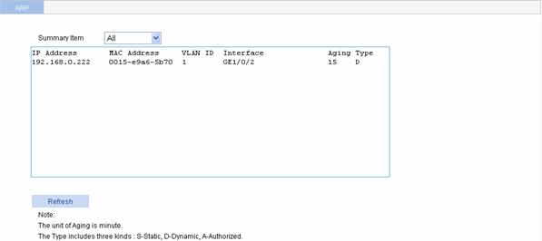
You can select All for Summary Item to view all the ARP entries, or specify a VLAN ID to view its ARP entries. The system displays ARP entries meeting the query criteria in the list box.
Table 3-1 describes the ARP entry items.
|
Item |
Description |
|
IP Address |
IP address of an ARP entry |
|
MAC Address |
MAC address of an ARP entry |
|
VLAN ID |
ID of the VLAN to which an ARP entry belongs |
|
Interface |
Outgoing interface for an ARP entry |
|
Aging |
Aging time of a dynamic ARP entry, in minutes "N/A" indicates unknown aging time or no aging time. |
|
Type |
Type of an ARP entry, which can be l S: Static ARP entry l D: Dynamic ARP entry l A: Authorized ARP entry |
IGMP Snooping Overview
Internet Group Management Protocol Snooping (IGMP Snooping) is a multicast constraining mechanism that runs on Layer 2 devices to manage and control multicast groups.
Configuring IGMP Snooping
Select Network > IGMP Snooping from the navigation tree to enter the page shown in Figure 4-1.
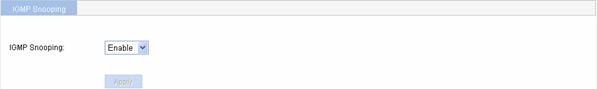
From the IGMP Snooping drop-down list box, select Enable or Disable to globally enable or disable IGMP Snooping.
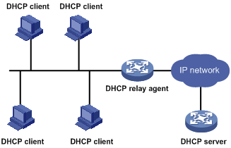
Introduction to DHCP
The fast expansion and growing complexity of networks result in scarce IP addresses assignable to hosts. Meanwhile, as many people need to take their laptops across networks, the IP addresses need to be changed accordingly. Therefore, related configurations on hosts become more complex. The Dynamic Host Configuration Protocol (DHCP) was introduced to solve these problems.
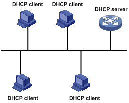
DHCP is built on a client-server model, in which a client sends a configuration request and then the server returns a reply to send configuration parameters such as an IP address to the client.
A typical DHCP application, as shown in Figure 5-1, includes a DHCP server and multiple clients (PCs and laptops).
Figure 5-1 A typical DHCP application
![]()
A DHCP client can get an IP address and other configuration parameters from a DHCP server on another subnet via a DHCP relay agent. For information about the DHCP relay agent, refer to Introduction to DHCP Relay Agent.
DHCP Address Allocation
Allocation mechanisms
DHCP supports three mechanisms for IP address allocation.
l Manual allocation: The network administrator assigns an IP address to a client like a WWW server, and DHCP conveys the assigned address to the client.
l Automatic allocation: DHCP assigns a permanent IP address to a client.
l Dynamic allocation: DHCP assigns an IP address to a client for a limited period of time, which is called a lease. Most DHCP clients obtain their addresses in this way.
Dynamic IP address allocation process
Figure 5-2 Dynamic IP address allocation process
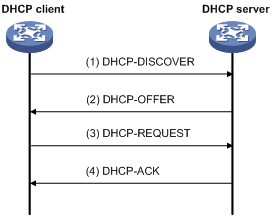
As shown in Figure 5-2, a DHCP client obtains an IP address from a DHCP server via four steps:
2) The client broadcasts a DHCP-DISCOVER message to locate a DHCP server.
3) A DHCP server offers configuration parameters such as an IP address to the client in a DHCP-OFFER message. The sending mode of the DHCP-OFFER is determined by the flag field in the DHCP-DISCOVER message.
4) If several DHCP servers send offers to the client, the client accepts the first received offer, and broadcasts it in a DHCP-REQUEST message to request the IP address formally.
5) All DHCP servers receive the DHCP-REQUEST message, but only the server from which the client accepts the offered IP address returns a DHCP-ACK message to the client, confirming that the IP address has been allocated to the client, or a DHCP-NAK unicast message, denying the IP address allocation.
![]()
l After the client receives the DHCP-ACK message, it will probe whether the IP address assigned by the server is in use by broadcasting a gratuitous ARP packet. If the client receives no response within the specified time, the client can use this IP address. Otherwise, the client sends a DHCP-DECLINE message to the server and requests an IP address again.
l IP addresses offered by other DHCP servers are still assignable to other clients.
IP address lease extension
The IP address dynamically allocated by a DHCP server to a client has a lease. When the lease expires, the DHCP server will reclaim the IP address. If the client wants to use the IP address longer, it has to extend the lease duration.
When the half lease duration elapses, the DHCP client sends to the DHCP server a DHCP-REQUEST unicast to extend the lease duration. Upon availability of the IP address, the DHCP server returns a DHCP-ACK unicast confirming that the client’s lease duration has been extended, or a DHCP-NAK unicast denying the request.
If the client receives no reply, it will broadcast another DHCP-REQUEST message for lease extension after 7/8 lease duration elapses. The DHCP server will handle the request as above mentioned.
Introduction to DHCP Server
Application environment
The DHCP server is well suited to the network where:
l It is hard to implement manual configuration and centralized management.
l The hosts are more than the assignable IP addresses and it is impossible to assign a fixed IP address to each host. For example, an ISP limits the number of hosts to access the Internet at a time, and therefore many hosts need to acquire IP addresses dynamically.
l A few hosts need fixed IP addresses.
DHCP Address Pool
In response to a client’s request, the DHCP server selects an IP address from an address pool and sends it together with other parameters to the client.
The address pool database is organized as a tree. The root of the tree is the address pool for natural networks, branches are address pools for subnets, and leaves are addresses statically bound to clients. For the same level address pools, a previously configured pool has a higher selection priority than a new one.
At the very beginning, subnetworks inherit network parameters and clients inherit subnetwork parameters. Therefore, common parameters, for example a DNS server address, should be configured at the highest (network or subnetwork) level of the tree.
After establishment of the inheritance relationship, the new configuration at the higher level (father) of the tree will be:
l Inherited if the lower level (child) has no such configuration, or
l Overridden if the lower level (child) has such configuration.
![]()
The IP address lease does not enjoy the inheritance attribute.
The DHCP server observes the following principles to select an address pool when assigning an IP address to a client:
1) If there is an address pool where an IP address is statically bound to the MAC address or ID of the client, the DHCP server will select this address pool and assign the statically bound IP address to the client.
2) Otherwise, the DHCP server will select the smallest address pool that contains the IP address of the receiving interface (if the client and the server reside in the same network segment), or the smallest address pool that contains the IP address specified in the giaddr field of the client’s request (if a DHCP relay agent is in-between). If no IP address is available in the address pool, the DHCP server will fail to assign an address to the client because it cannot assign an IP address from the father address pool to the client.
For example, two address pools are configured on the DHCP server, 1.1.1.0/24 and 1.1.1.0/25. If the IP address of the interface receiving DHCP requests is 1.1.1.1/25, the DHCP server will select IP addresses for clients from address pool 1.1.1.0/25. If no IP address is available in the address pool, the DHCP server will fail to assign addresses to clients. If the IP address of the interface receiving DHCP requests is 1.1.1.130/25, the DHCP server will select IP addresses for clients from the 1.1.1.0/24 address pool.
IP address allocation sequence
A DHCP server assigns an IP address to a client according to the following sequence:
1) The IP address manually bound to the client’s MAC address or ID
2) The IP address that was ever assigned to the client
3) The IP address designated by the Option 50 field in the DHCP-DISCOVER message
4) The first assignable IP address found in a proper DHCP address pool
5) The IP address that was a conflict or passed its lease duration
If no IP address is assignable, the server will not respond.
Introduction to DHCP Relay Agent
Application environment
Since DHCP clients request IP addresses via broadcast messages, the DHCP server and clients must be on the same subnet. Therefore, a DHCP server must be available on each subnet, which is not practical.
DHCP relay agent solves the problem. Via a relay agent, DHCP clients communicate with a DHCP server on another subnet to obtain configuration parameters. Thus, DHCP clients on different subnets can contact the same DHCP server, and centralized management and cost reduction are achieved.
Fundamentals
Figure 5-3 shows a typical application of the DHCP relay agent.
Figure 5-3 DHCP relay agent application
No matter whether a relay agent exists or not, the DHCP server and client interact with each other in a similar way (see section Dynamic IP address allocation process). The following describes the forwarding process on the DHCP relay agent.
Figure 5-4 DHCP relay agent work process
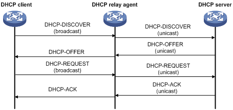
As shown in Figure 5-4, the DHCP relay agent works as follows:
1) After receiving a DHCP-DISCOVER or DHCP-REQUEST broadcast message from a DHCP client, the DHCP relay agent fills the giaddr field of the message with its IP address and forwards the message to the designated DHCP server in unicast mode.
2) Based on the giaddr field, the DHCP server returns an IP address and other configuration parameters to the relay agent, which conveys them to the client.
Introduction to DHCP Client
With the DHCP client enabled on an interface, the interface will use DHCP to obtain configuration parameters such as an IP address from a DHCP server.
Protocols and Standards
l RFC 2131: Dynamic Host Configuration Protocol
l RFC 2132: DHCP Options and BOOTP Vendor Extensions
l RFC 1542: Clarifications and Extensions for the Bootstrap Protocol
l RFC 3046: DHCP Relay Agent Information Option
Configuring DHCP
Configuration Overview
Through the DHCP module of the Web management interface, you can configure the device as a DHCP server or a DHCP relay agent. After you enable the DHCP client on an interface, the interface can automatically acquire an IP address through DHCP. For detailed configuration procedure, refer to Interface Management in Device.
Configuring the DHCP server
Perform the tasks in Table 5-1 to configure the DHCP sever.
Table 5-1 DHCP server configuration task list
|
Task |
Remarks |
|
Required Disabled by default. |
|
|
Optional Enabled with the DHCP server, the interface assigns IP addresses from the address pool of the DHCP server to clients. By default, the DHCP server is enabled on the interface. |
|
|
Required Complete either task or both tasks. |
|
Configuring the DHCP relay agent
Perform the tasks in Table 5-2 to configure the DHCP relay agent.
Table 5-2 DHCP relay agent configuration task list
|
Task |
Remarks |
|
Required Disabled by default. |
|
|
Required To improve reliability, you can configure a DHCP server group consisting of multiple DHCP servers on a network. After you correlate an interface to the DHCP server group, the DHCP messages arriving at the interface are forwarded to all the servers in this group. |
|
|
Required Configure the current interface as a DHCP relay agent and correlate the interface to a DHCP server group. By default, the DHCP server is enabled on the interface. |
Enabling DHCP
Select Network > DHCP from the navigation tree to enter the default Global Configuration page, as shown in Figure 5-5.
Figure 5-5 DHCP global configuration
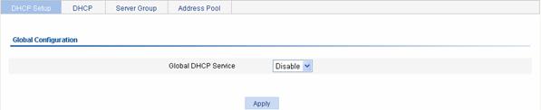
Table 5-3 describes the DHCP configuration items.
Table 5-3 DHCP configuration items
|
Item |
Description |
|
Global DHCP Service |
Enable or disable the DHCP service globally. |
Return to DHCP server configuration task list.
Return to DHCP relay agent configuration task list.
Enabling the DHCP Server on an Interface
Select Network > DHCP from the navigation tree, and then click the DHCP tab to enter the page shown in Figure 5-6.
Click ![]() to configure the DHCP service type of the
specified interface.
to configure the DHCP service type of the
specified interface.
Figure 5-6 DHCP service type configuration
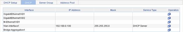
Table 5-4 describes the DHCP server configuration items.
Table 5-4 DHCP server configuration items
|
Item |
Description |
|
Interface |
Name of the interface to be configured |
|
Service Type: DHCP Server |
Configures the service type as DHCP server, that is, enables the DHCP server on the interface. |
Return to DHCP server configuration task list.
Configuring a Static Address Pool for the DHCP Server
Select Network > DHCP from the navigation tree and then click the Address Pool tab to enter the DHCP address pool configuration page.
Select Static Binding, and all the static address pools are displayed, as shown in Figure 5-7.
Click Add to create a static IP address pool.
Figure 5-7 Static address pool configuration
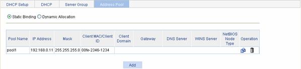
Table 5-5 describes the DHCP static address pool configuration items.
Table 5-5 DHCP static address pool configuration items
|
Item |
Description |
|
Pool Name |
Specifies the name of a DHCP static address pool. |
|
IP Address |
Specifies the IP address and mask of a static binding. The IP address cannot be that of the DHCP server interface; otherwise, IP address conflicts may occur, and the client cannot obtain the IP address. |
|
Mask |
|
|
Client MAC/Client ID |
Specifies either the MAC address or the ID of the client in the static binding.
The client ID of the static binding should be consistent with the ID of the client; otherwise, the client cannot obtain the IP address. |
|
Client Domain |
Specifies a domain name suffix that the DHCP client acquires from the DHCP address pool. With the domain name suffix specified, the DHCP server assigns the domain name along with an IP address to the client. |
|
Gateway |
Specifies a gateway IP address that the DHCP client acquires from the DHCP address pool. A gateway forwards the data sent from the client to the server or host on another network segment. With the gateway IP address specified, the DHCP server assigns the gateway IP address along with an IP address to the client. You can configure up to eight gateways, separated with commas. |
|
DNS Server |
Specifies the IP address of a DNS server that the DHCP client acquires from the DHCP address pool. In order for the client to access the Internet using a domain name, the DHCP server assigns the specified DNS server address along with an IP address to the client. You can configure up to eight DNS servers, separated with commas. |
|
WINS Server |
Specifies the IP address of a WINS server that the DHCP client acquires from the DHCP address pool. By specifying b-node, you choose not to configure the WINS server address. You can configure up to eight WINS servers, separated with commas. |
|
NetBIOS Node Type |
Specifies a NetBIOS node type that the DHCP client acquires from the DHCP address pool. |
Return to DHCP server configuration task list.
Configuring a Dynamic Address Pool for the DHCP Server
Select Network > DHCP from the navigation tree and then click the Address Pool tab to enter the DHCP address pool configuration page. Select Dynamic and all the dynamic address pools are displayed, as shown in Figure 5-8.
Click Add to create a dynamic IP address pool.
Figure 5-8 Dynamic address pool configuration
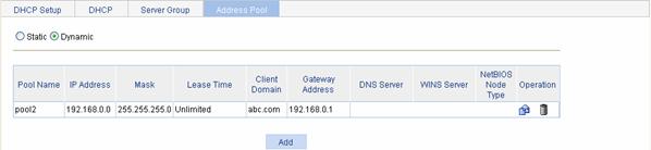
Table 5-6 describes the DHCP dynamic address pool configuration items.
Table 5-6 DHCP dynamic address pool configuration items
|
Item |
Description |
|
|
Pool Name |
Specifies the name of a DHCP dynamic address pool. |
|
|
IP Address |
Specifies an IP address range, which is an IP segment. The IP addresses in use (such as the IP addresses of the gateway and FTP server) should be excluded from assignment; otherwise, one IP address may be assigned to two clients, causing address conflicts. |
|
|
Mask |
||
|
Lease Time |
Unlimited |
Specifies the lease duration of IP addresses dynamically assigned. Unlimited indicates that the address lease duration is not limited. |
|
days/hours/minutes |
||
|
Client Domain |
Specifies a domain name suffix that the DHCP client acquires from the DHCP address pool. With the domain name suffix specified, the DHCP server assigns the domain name along with an IP address to a client. |
|
|
Gateway Address |
Specifies a gateway IP address that the DHCP client acquires from the DHCP address pool. A gateway forwards the data sent from the client to the server or host on another network segment. With the gateway IP address specified, the DHCP server assigns the gateway IP address along with an IP address to the client. You can configure up to eight gateways, separated with commas. |
|
|
DNS Server |
Specifies the IP address of a DNS server that the DHCP client acquires from the DHCP address pool. In order for a client to access the Internet using a domain name, the DHCP server assigns the specified DNS server address along with an IP address to the client. You can configure up to eight DNS servers, separated with commas. |
|
|
WINS Server |
Specifies the IP address of a WINS server that the DHCP client acquires from the DHCP address pool. By specifying b-node, you choose not to specify the WINS server address. You can configure up to eight WINS servers, separated with commas. |
|
|
NetBIOS Node Type |
Specifies a NetBIOS node type that the DHCP client acquires from the DHCP address pool. |
|
Return to DHCP server configuration task list.
Configuring a DHCP Server Group
Select Network > DHCP from the navigation tree and then click the DHCP Server Group tab to enter the DHCP server group configuration page, as shown in Figure 5-9.
Click Add to create a DHCP server group.
Figure 5-9 DHCP server group configuration
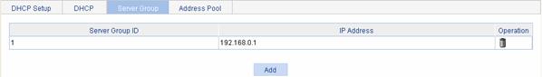
Table 5-7 describes the DHCP server group configuration items.
Table 5-7 DHCP server group configuration items
|
Item |
Description |
|
Server Group ID |
Specifies the DHCP server group ID. You can create up to 20 DHCP server groups. |
|
IP Address |
Specifies the IP addresses of the DHCP servers in the DHCP server group. The IP address of a DHCP server in the group cannot be on the same network segment as that of the DHCP relay agent interface; otherwise, DHCP clients may fail to obtain IP addresses. |
Return to DHCP relay agent configuration task list.
Enabling the DHCP Relay Agent on an Interface
Select Network > DHCP from the navigation tree, and then click the DHCP tab to enter the page shown in Figure 5-6.
Click ![]() to configure the DHCP service type of the
specified interface.
to configure the DHCP service type of the
specified interface.
Table 5-8 describes the DHCP relay agent configuration items.
Table 5-8 DHCP relay agent configuration items
|
Item |
Description |
|
Interface |
Name of the interface to be configured |
|
Service Type: DHCP Relay |
Configures the service type as DHCP relay, that is, enables the DHCP relay agent on the interface. |
|
Server Group ID |
Configures the DHCP server group to which the interface is correlated. A server group can correspond to multiple interfaces. |
Return to DHCP relay agent configuration task list.
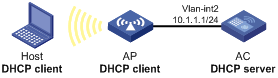
DHCP Configuration Examples
Network requirements
l As shown in Figure 5-10, DHCP server (AC) assigns IP addresses to clients on subnet 10.1.1.0/24. The IP address of VLAN-interface 2 on AC is 10.1.1.1/24.
l In subnet 10.1.1.0/24, the lease is ten days and twelve hours.
Configuration procedure
# Specify IP addresses for interfaces (omitted).
# Enable DHCP.
l Select Network > DHCP from the navigation tree and enter the default Global Configuration page.
l Select Enable for the Global DHCP Service.
l Click Apply.
# Enable the DHCP server on VLAN-interface 2 (You can skip this step by using the default settings).
# Configure the DHCP dynamic address pool.
l Select Network > DHCP from the navigation tree and then click the Address Pool tab.
l Select Dynamic and then click Add.
l Type 0 for Pool Name.
l Type 10.1.1.0 for IP Address.
l Type 255.255.255.0 for Mask.
l Set the Lease Time to 10 days, 12 hours, and 0 minutes.
l Type 10.1.1.1 for DNS Server.
l Click Apply.
Configuration Guidelines
1) When configuring an address pool on the DHCP server:
l If the DHCP server and DHCP clients are on the same subnet, make sure the address pool is on the same network segment as the interface with the DHCP server enabled; otherwise, the client will fail to obtain an IP address.
l If a DHCP client obtains an IP address via a DHCP relay agent, an IP address pool on the same network segment as the DHCP relay agent must be configured; otherwise, the client will fail to obtain an IP address.
2) The Address Pool page displays only the static and dynamic address pools that have both a name and service type configured. An address pool that has only a name specified cannot be displayed in the page.
3) An address pool can be either static or dynamic, but not both.
4) Only one service type among DHCP Server and DHCP Relay can be selected for an interface.
5) The DHCP Server and DHCP Relay service types are only used for interfaces with IP addresses manually configured.
6) The DHCP server configuration is supported only on Layer 3 Ethernet interfaces (or subinterfaces). The DHCP server subaddress pool configuration is not supported on serial interfaces.
7) The DHCP relay agent configuration is supported only on Layer 3 Ethernet interfaces (or subinterfaces).
8) If an Ethernet subinterface serves as a DHCP relay agent, it conveys IP addresses only to subinterfaces of DHCP clients. In this case, a PC cannot obtain an IP address as a DHCP client.
Overview
Domain Name System (DNS) is a distributed database used by TCP/IP applications to translate domain names into corresponding IP addresses. With DNS, you can use easy-to-remember domain names in some applications and let the DNS server translate them into correct IP addresses.
There are two types of DNS services, static and dynamic. After a user specifies a name, the device checks the local static name resolution table for an IP address. If no IP address is available, it contacts the DNS server for dynamic name resolution, which takes more time than static name resolution. Therefore, some frequently queried name-to-IP address mappings are stored in the local static name resolution table to improve efficiency.
Static Domain Name Resolution
Configuring static domain name resolution is to set up mappings between domain names and IP addresses manually. IP addresses of the corresponding domain names can be found in the static domain resolution table when you use applications such as telnet.
Dynamic Domain Name Resolution
Resolving procedure
Dynamic domain name resolution is implemented by querying the DNS server. The resolution procedure is as follows:
1) A user program sends a name query to the resolver of the DNS client.
2) The DNS resolver looks up the local domain name cache for a match. If a match is found, it sends the corresponding IP address back. If not, it sends a query to the DNS server.
3) The DNS server looks up the corresponding IP address of the domain name in its DNS database. If no match is found, it sends a query to a higher level DNS server. This process continues until a result, whether successful or not, is returned.
4) The DNS client returns the resolution result to the application after receiving a response from the DNS server.
Figure 6-1 Dynamic domain name resolution
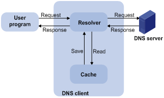
Figure 6-1 shows the relationship between the user program, DNS client, and DNS server. The resolver and cache comprise the DNS client. The user program and DNS client can run on the same device or different devices, while the DNS server and the DNS client usually run on different devices.
Dynamic domain name resolution allows the DNS client to store latest mappings between domain names and IP addresses in the dynamic domain name cache. There is no need to send a request to the DNS server for a repeated query next time. The mappings are removed from the cache after some time to ensure latest entries are obtained from the DNS server. The DNS server decides how long a mapping is valid, and the DNS client gets the aging time from DNS messages.
DNS suffixes
The DNS client normally holds a list of suffixes which can be defined by users. It is used when the name to be resolved is incomplete. The resolver can supply the missing part. For example, a user can configure com as the suffix for aabbcc.com. After that, the user only needs to type aabbcc, and the resolver will add the suffix and delimiter. The following describes more details.
l If there is no dot in the inputted domain name (for example, aabbcc), the resolver will consider it a host name and add a DNS suffix before query. If no match is found after all the configured suffixes are used respectively, the original domain name (for example, aabbcc) is used for query.
l If there is a dot in the inputted domain name (for example, www.aabbcc), the resolver will directly use this domain name for query. If the query fails, the resolver adds a DNS suffix for another query.
l If the dot is at the end of the inputted domain name (for example, aabbcc.com.), the resolver will consider it a fully qualified domain name (FQDN) and return the query result, successful or failed. Hence, the dot “.” at the end of the domain name is called the terminating symbol.
DNS Proxy
Introduction to DNS proxy
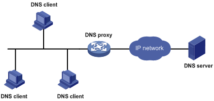
A DNS proxy forwards DNS requests and replies between DNS clients and a DNS server.
As shown in Figure 6-2, a DNS client sends a DNS request to the DNS proxy, which forwards the request to the designated DNS server, and conveys the reply from the DNS server to the client.
The DNS proxy simplifies network management. When the DNS server address is changed, you only need to change the configuration on the DNS proxy instead of on each DNS client.
Figure 6-2 DNS proxy networking application
Operation of a DNS proxy
1) A DNS client considers the DNS proxy as the DNS server, and sends a DNS request to the DNS proxy, that is, the destination address of the request is the IP address of the DNS proxy.
2) The DNS proxy searches the local static domain name resolution table after receiving the request. If the requested information exists in the table, the DNS proxy returns a DNS reply to the client.
3) If the requested information does not exist in the static domain name resolution table, the DNS proxy sends the request to the designated DNS server for domain name resolution.
4) After receiving a reply from the DNS server, the DNS proxy forwards the reply to the DNS client.
Configuring DNS
Configuration Overview
DNS provides three functions, static name resolution, dynamic domain name resolution, and DNS proxy.
l Static name resolution: Name resolution is carried out through manually configured name resolution entries.
l Dynamic name resolution: A device resolves domain names through the DNS server.
l DNS proxy: You can configure a device as a DNS proxy.
![]()
If both static domain name resolution and dynamic domain name resolution are configured, the device first checks the static name resolution table for an IP address. If no IP address is available, it then contacts the DNS server for dynamic name resolution.
Configuring static name resolution table
Perform the tasks in Table 6-1 to configure static name resolution table.
Table 6-1 Static name resolution table configuration task list
|
Task |
Remarks |
|
Required By default, no host name-to-IP address mappings are configured in the static domain name resolution table. |
Configuring dynamic domain name resolution
Perform the tasks in Table 6-2 to configure dynamic domain name resolution.
Table 6-2 Dynamic domain name resolution configuration task list
|
Task |
Remarks |
|
Required Enable dynamic domain name resolution. This function is disabled by default. |
|
|
Required Not configured by default. |
|
|
Optional Not configured by default. |
Configuring DNS proxy
Perform the tasks in Table 6-3 to configure DNS proxy.
Table 6-3 DNS proxy configuration task list
|
Task |
Remarks |
|
Required Configure the device as a DNS proxy. By default, the device is not a DNS proxy. |
|
|
Required Not configured by default. |
Configuring Static Name Resolution Table
Select Network > DNS from the navigation tree to enter the default Static Domain Name Resolution configuration page, as shown in Figure 6-3. Click Add to create a static host name-to-IP address mapping.
Figure 6-3 Static domain name resolution configuration
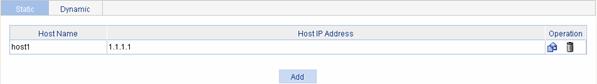
Table 6-4 describes the static name resolution table configuration items.
Table 6-4 Static name resolution table configuration items
|
Item |
Description |
|
Host Name |
Configure the mapping between a host name and an IP address in the static domain mane table. Each host name corresponds to only one IP address. If you configure multiple IP addresses for a host name, the last configured one takes effect. You can create up to 50 static host name-to-IP address mappings. |
|
Host IP Address |
Return to Static name resolution table configuration task list.
Configuring Dynamic Domain Name Resolution
Select Network > DNS from the navigation tree and then click the Dynamic Domain Name Resolution tab to enter the default configuration page, as shown in Figure 6-4.
Figure 6-4 Dynamic domain name resolution configuration
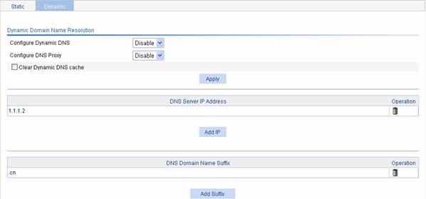
Table 6-5 describes the dynamic domain name resolution configuration items.
Table 6-5 Dynamic domain name resolution configuration items
|
Item |
Description |
|
Configure Dynamic DNS |
Enables or disables dynamic domain name resolution. |
|
Clear Dynamic DNS cache |
Sets whether to remove all the information from the dynamic DNS cache. |
Return to Dynamic domain name resolution configuration task list.
Configuring DNS Proxy
Select Network > DNS from the navigation tree and then click the Dynamic Domain Name Resolution tab to enter the default configuration page, as shown in Figure 6-4.
Table 6-6 describes the DNS proxy configuration items.
Table 6-6 DNS proxy configuration items
|
Item |
Description |
|
Configure DNS proxy |
Enables or disables DNS proxy on the device. |
Return to DNS proxy configuration task list.
Configuring DNS Server Addresses
Select Network > DNS from the navigation tree and then click the Dynamic Domain Name Resolution tab to enter the default configuration page, as shown in Figure 6-4. Click Add IP to configure DNS server addresses.
Table 6-7 describes the DNS server address configuration items.
Table 6-7 DNS server address configuration items
|
Item |
Description |
|
DNS Server IP Address |
Specifies the IP addresses of DNS servers. You can configure up to six DNS servers. |
Return to Dynamic domain name resolution configuration task list.
Return to DNS proxy configuration task list.
Configuring Domain Name Suffixes
Select Network > DNS from the navigation tree and then click the Dynamic Domain Name Resolution tab to enter the default configuration page, as shown in Figure 6-4. Click Add Suffix to configure domain name suffixes.
Table 6-8 describes the domain name suffix configuration items.
Table 6-8 Domain name suffix configuration items
|
Item |
Description |
|
DNS Domain Name Suffix |
Specifies DNS domain name suffixes. You can configure up to 10 DNS domain name suffixes. |
Return to Dynamic domain name resolution configuration task list.
DNS Configuration Examples
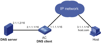
Network requirements
l The IP address of the DNS server is 2.1.1.2/16 and the domain name suffix is com.
l AC serving as a DNS client uses dynamic domain name resolution to access the host with the domain name host.com and the IP address 3.1.1.1/16, as shown in Figure 6-5.
Figure 6-5 Network diagram for DNS
Configuration procedure
![]()
Before performing the following configuration, make sure that AC and the host are reachable to each other, and related configurations are made on both AC and the host. For the IP addresses of the interfaces, see Figure 6-5. In addition, the mapping between host name host.com and IP address 3.1.1.1/16 has been configured on the DNS server that works normally.
# Enable dynamic domain name resolution.
l Select Network > DNS from the navigation tree and click the Dynamic Domain Name Resolution tab.
l Select Enable for Configure Dynamic DNS.
l Select Disable for Configure DNS Proxy.
l Click Apply.
# Configure the DNS server address.
l Click Add IP on the Dynamic Domain Name Resolution page.
l Type 2.1.1.2 for DNS Server IP Address.
l Click Apply.
# Configure the domain name suffix.
l Click Add Suffix on the Dynamic Domain Name Resolution page.
l Type com for DNS Domain Name Suffix.
l Click Apply.
![]()
The term “router” in this document refers to a router in a generic sense or a WLAN device running routing protocols.
Overview
Routers are responsible for routing packets on the Internet. A router selects an appropriate route according to the destination address of a received packet and forwards the packet to the next router. The last router on the path is responsible for sending the packet to the destination host.
Routing Table
Routers forward packets through a routing table. Each entry in the table specifies which physical interface a packet should go out to reach the next hop (the next router) or the directly connected destination.
Routes in a routing table fall into three categories by origin:
l Direct routes: Routes discovered by data link protocols, also known as interface routes.
l Static routes: Routes that are manually configured.
l Dynamic routes: Routes that are discovered dynamically by routing protocols.
A route entry has the following items:
l Destination IP address: Destination IP address or destination network.
l Mask (IPv4)/prefix length (IPv6): Specifies, together with the destination address, the address of the destination network.
l Outbound interface: Specifies the interface through which a matching IP packet is to be forwarded.
l Nexthop: Specifies the address of the next hop router on the path.
l Preference for the route: Routes to the same destination may be found by various routing protocols or manually configured, and routing protocols and static routes have different priorities configured. The route with the highest priority (the smallest value) will be selected as the optimal route.
Static Route
A static route is manually configured. If a network’s topology is simple, you only need to configure static routes for the network to work normally. The proper configuration and usage of static routes can improve network performance and ensure bandwidth for important network applications.
The disadvantage of using static routes is that they cannot adapt to network topology changes. If a fault or a topological change occurs in the network, some routes will be unreachable. In this case, the network administrator has to modify the static routes manually.
While configuring a static route, you can specify either the output interface or the next hop address as needed. The nexthop address cannot be a local interface’s IP address; otherwise, the route configuration will not take effect.
Actually, it is necessary to identify next hop addresses for all route entries because the router needs to use the next hop address of a matching entry to resolve the corresponding link layer address.
Default Route
A router selects the default route when it cannot find any matching entry in the routing table for a packet. If there is no default route, the packet will be discarded and an ICMP packet will be sent to the source to report that the destination is unreachable.
You can configure the default route, and some dynamic routing protocols can also generate the default route.
l An IPv4 static default route has both its destination IP address and mask configured as 0.0.0.0.
l An IPv6 static default route has its destination IP address and prefix configured as ::/0.
Configuring IPv4 Routing
Displaying the IPv4 Active Route Table
Select Network > IPv4 Routing from the navigation tree to enter the page shown in Figure 7-1.
Figure 7-1 IPv4 active route table
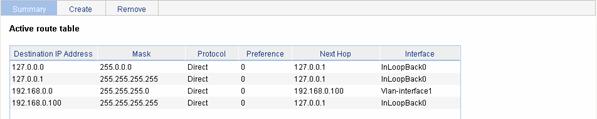
Table 7-1 describes the fields of the IPv4 active route table:
Table 7-1 Description of the fields of the IPv4 active route table
|
Field |
Description |
|
Destination IP Address |
Destination IP address and subnet mask of the IPv4 route |
|
Mask |
|
|
Protocol |
Protocol that discovered the IPv4 route |
|
Preference |
Preference value for the IPv4 route The smaller the number, the higher the preference. |
|
Next Hop |
Nexthop IP address of the IPv4 route |
|
Interface |
Outgoing interface of the IPv4 route. Packets destined for the specified network segment will be sent out the interface. |
Creating an IPv4 Static Route
Select Network > IPv4 Routing from the navigation tree and click the Create tab to enter the IPv4 static route configuration page, as shown in Figure 7-2.
Figure 7-2 Create an IPv4 static route
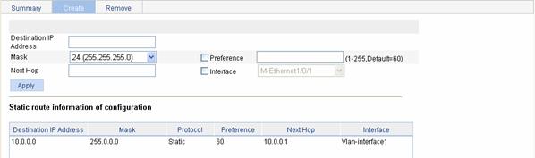
Table 7-2 describes the IPv4 static route configuration items:
Table 7-2 IPv4 static route configuration items
|
Item |
Description |
|
Destination IP Address |
Type the destination host or network IP address, in dotted decimal notation. |
|
Mask |
Type the mask of the destination IP address. Select a mask length (number of consecutive 1s in the mask) or a mask in dotted decimal notation from the drop-down list. |
|
Preference |
Set a preference value for the static route. The smaller the number, the higher the preference. For example, specifying the same preference for multiple static routes to the same destination enables load sharing on the routes, while specifying different preferences enables route backup. |
|
Next Hop |
Type the nexthop IP address, in dotted decimal notation. |
|
Interface |
Select the outgoing interface. You can select any available interface, for example, a virtual interface, of the device. If you select NULL 0, the destination IP address is unreachable. |
Configuring IPv6 Routing
![]()
Support for this feature depends on the device model.
Displaying the IPv6 Active Route Table
Select Network > IPv6 Routing from the navigation tree to enter the page shown in Figure 7-3.
Figure 7-3 IPv6 active route table
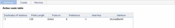
Table 7-3 describes the fields of the IPv6 active route table:
Table 7-3 Description of the fields of the IPv6 active route table
|
Field |
Description |
|
Destination IP Address |
Destination IP address and prefix length of the IPv6 route |
|
Prefix Length |
|
|
Protocol |
Protocol that discovered the IPv6 route |
|
Preference |
Preference value for the IPv6 route The smaller the number, the higher the preference. |
|
Next Hop |
Nexthop IP address of the IPv6 route |
|
Interface |
Outgoing interface of the IPv6 route. Packets destined for the specified network segment will be sent out the interface. |
Creating an IPv6 Static Route
Select Network > IPv6 Routing from the navigation tree and click the Create tab to enter the IPv6 static route configuration page, as shown in Figure 7-4.
Figure 7-4 Create an IPv6 static route
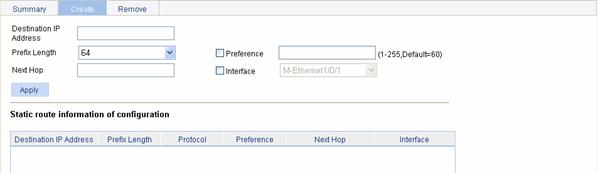
Table 7-4 describes the IPv6 static route configuration items:
Table 7-4 IPv6 static route configuration items
|
Item |
Description |
|
Destination IP Address |
Type the destination host or network IP address, in the X:X::X:X format. The 128-bit destination IPv6 address is a hexadecimal address with eight parts separated by colons (:). Each part is represented by a 4-digit hexadecimal integer. |
|
Prefix Length |
Type the prefix length of the destination IPv6 address. |
|
Preference |
Set a preference value for the static route. The smaller the number, the higher the preference. For example, specifying the same preference for multiple static routes to the same destination enables load sharing on the routes, while specifying different priorities for them enables route backup. |
|
Next Hop |
Type the nexthop address, in the same format as the destination IP address. |
|
Interface |
Select the outgoing interface. You can select any available interface, for example, a virtual interface, of the device. If you select NULL 0, the destination IPv6 address is unreachable. |
Static Route Configuration Examples
IPv4 Static Route Configuration Example
Network requirements
The interface IP addresses of Switch A, Switch B and AC and the hosts’ IP addresses and masks are shown in Figure 7-5. IPv4 static routes need to be configured on Switch A, Switch B and AC for any two hosts to communicate with each other.
Figure 7-5 Network diagram for IPv4 static route configuration
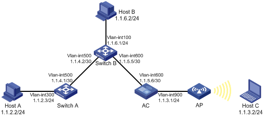
Configuration outlines
1) On Switch A, configure a default route with Switch B as the next hop.
2) On Switch B, configure one static route with Switch A as the next hp and the other with AC as the next hop.
3) On AC, configure a default route with Switch B as the next hop.
Configuration procedure
1) Configure the IP addresses of the interfaces (omitted)
2) Configure IPv4 static routes
# Configure a default route with the next hop address 1.1.4.2 on Switch A (omitted).
# Configure two static routes on Switch B: one with destination address 1.1.2.0/24 and next hop address 1.1.4.1, and the other with destination address 1.1.3.0/24 and next hop address 1.1.5.6 (omitted).
# Configure a default route on AC.
l After you log in to the Web interface of AC, select Network > IPv4 Routing from the navigation tree and then click the Create tab to enter the IPv4 static route configuration page.
l Type 0.0.0.0 for Destination IP Address.
l Select 0 (0.0.0.0) from the Mask drop-down list.
l Type 1.1.5.5 for Next Hop.
l Click Apply.
3) Configure the hosts
As shown in Figure 7-5, configure the IPv4 addresses of the hosts and configure the default gateways of Host A, B, and C as 1.1.2.3, 1.1.6.1, and 1.1.3.1 respectively. The detailed configuration steps are not covered.
4) Verify the configuration
# Display the route table.
Enter the IPv4 route page of Switch A, Switch B, and AC respectively to verify that the newly configured static routes are displayed as active routes on the page.
# Use the ping command for verification.
Ping Host C from Host B (assuming both hosts run Windows XP).
C:\Documents and Settings\Administrator>ping 1.1.3.2
Pinging 1.1.3.2 with 32 bytes of data:
Reply from 1.1.3.2: bytes=32 time=1ms TTL=128
Reply from 1.1.3.2: bytes=32 time=1ms TTL=128
Reply from 1.1.3.2: bytes=32 time=1ms TTL=128
Reply from 1.1.3.2: bytes=32 time=1ms TTL=128
Ping statistics for 1.1.3.2:
Packets: Sent = 4, Received = 4, Lost = 0 (0% loss),
Approximate round trip times in milli-seconds:
Minimum = 1ms, Maximum = 1ms, Average = 1ms
# Use the tracert command for verification.
Use the tracert command on Host B to check the reachability to Host A (assuming both hosts run Windows XP).
C:\Documents and Settings\Administrator>tracert 1.1.2.2
Tracing route to 1.1.2.2 over a maximum of 30 hops
1 <1 ms <1 ms <1 ms 1.1.6.1
2 <1 ms <1 ms <1 ms 1.1.4.1
3 1 ms <1 ms <1 ms 1.1.2.2
Trace complete.
IPv6 Static Route Configuration Example
Network requirements
The interface IP addresses of Switch A, Switch B and AC and the hosts’ IP addresses and masks are shown in Figure 7-6. IPv6 static routes need to be configured on Switch A, Switch B and AC for any two hosts to communicate with each other.
Figure 7-6 Network diagram for IPv6 static route configuration
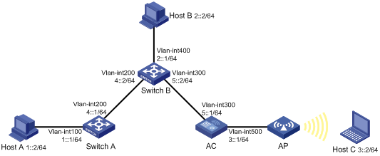
Configuration outlines
1) On Switch A, configure a default route with Switch B as the next hop.
2) On Switch B, configure one static route with Switch A as the next hop and the other with AC as the next hop.
3) On AC, configure a default route with Switch B as the next hop.
Configuration procedure
1) Configure IPv6 addresses for interfaces (omitted)
2) Configure IPv6 static routes on the switches.
# Configure a default route with the next hop address 4::2 on Switch A (omitted).
# Configure two static routes on Switch B: one with destination address 1::/64 and next hop address 4::1, and the other with destination address 3::/64 and next hop address 5::1 (omitted).
# Configure a default route on AC.
l After you log in to the Web interface of AC, select Network > IPv6 Routing from the navigation tree and then click the Create tab to enter the IPv6 static route configuration page.
l Type :: for Destination IP Address.
l Select 0 from the Prefix Length drop-down list.
l Type 5::2 for Next Hop.
l Click Apply.
3) Configure the IP addresses of hosts and gateways.
As shown in Figure 7-6, configure the IPv6 addresses of the hosts and configure the default gateways of Host A, B, and C as 1::1, 2::1, and 3::1 respectively. The detailed configuration steps are not covered.
4) Verify the configuration.
# Display the route table.
Enter the IPv6 route page of Switch A, Switch B, and AC respectively to verify that the newly configured static routes are displayed as active routes on the page.
# Use the ping command for verification.
Ping Host C from Switch A.
<SwitchA> system-view
[SwitchA] ping ipv6 3::2
PING 3::2 : 56 data bytes, press CTRL_C to break
Reply from 3::2
bytes=56 Sequence=1 hop limit=254 time = 63 ms
Reply from 3::2
bytes=56 Sequence=2 hop limit=254 time = 62 ms
Reply from 3::2
bytes=56 Sequence=3 hop limit=254 time = 62 ms
Reply from 3::2
bytes=56 Sequence=4 hop limit=254 time = 63 ms
Reply from 3::2
bytes=56 Sequence=5 hop limit=254 time = 63 ms
--- 3::2 ping statistics ---
5 packet(s) transmitted
5 packet(s) received
0.00% packet loss
round-trip min/avg/max = 62/62/63 ms
Precautions
When configuring a static route, note the following:
1) If you do not specify the preference when configuring a static route, the default preference will be used. Reconfiguration of the default preference applies only to newly created static routes. Currently, the Web interface does not support configuration of the default preference.
2) When configuring a static route, the static route does not take effect if you specify the next hop address first and then configure it as the IP address of a local interface, such as an Ethernet interface and VLAN interface.
3) When specifying the output interface, note that:
l If NULL 0 or a loopback interface is specified as the output interface, there is no need to configure the next hop address.
l If a point-to-point interface is specified as the output interface, you don’t need to specify the next hop, and there is no need to change the configuration after the peer address has changed. For example, a PPP interface obtains the peer’s IP address through PPP negotiation, and therefore you only need to specify it as the output interface.
l If the output interface is an NBMA or P2MP interface, which supports point-to-multipoint networks, the IP address-to-link layer address mapping must be established. Therefore, you are recommended to specify the next hop IP address when you configure it as the output interface.
l If you want to specify a broadcast interface (such as an Ethernet interface, virtual template, or VLAN interface) as the output interface, which may have multiple next hops, you must specify the next hop at the same time.
Overview
The service management module provides six types of services: FTP, Telnet, SSH, SFTP, HTTP and HTTPS. You can enable or disable the services as needed. In this way, the performance and security of the system can be enhanced, thus secure management of the device can be achieved.
The service management module also provides the function to modify HTTP and HTTPS port numbers, and the function to associate the FTP, HTTP, or HTTPS service with an ACL, thus reducing attacks of illegal users on these services.
FTP service
The File Transfer Protocol (FTP) is an application layer protocol for sharing files between server and client over a TCP/IP network.
Telnet service
The Telnet protocol is an application layer protocol that provides remote login and virtual terminal functions on the network.
SSH service
Secure Shell (SSH) offers an approach to securely logging in to a remote device. By encryption and strong authentication, it protects devices against attacks such as IP spoofing and plain text password interception.
SFTP service
The secure file transfer protocol (SFTP) is a new feature in SSH2.0. SFTP uses the SSH connection to provide secure data transfer. The device can serve as the SFTP server, allowing a remote user to log in to the SFTP server for secure file management and transfer. The device can also serve as an SFTP client, enabling a user to login from the device to a remote device for secure file transfer.
HTTP service
The Hypertext Transfer Protocol (HTTP) is used for transferring web page information across the Internet. It is an application-layer protocol in the TCP/IP protocol suite.
You can log in to the device using the HTTP protocol with HTTP service enabled, accessing and controlling the device with Web-based network management.
HTTPS service
The Secure HTTP (HTTPS) refers to the HTTP protocol that supports the Security Socket Layer (SSL) protocol.
The SSL protocol of HTTPS enhances the security of the device in the following ways:
l Uses the SSL protocol to ensure the legal clients to access the device securely and prohibit the illegal clients;
l Encrypts the data exchanged between the HTTPS client and the device to ensure the data security and integrity, thus realizing the security management of the device;
l Defines certificate attribute-based access control policy for the device to control the access right of the client, in order to further avoid attacks from illegal clients.
Configuring Service Management
Select Network > Service from the navigation tree at the left side of the interface to enter the service management configuration page, as shown in Figure 8-1.
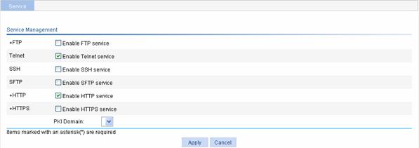
Table 8-1 shows the detailed configuration for service management.
Table 8-1 Service management configuration items
|
Item |
Description |
|
|
FTP |
Enable FTP service |
Specifies whether to enable the FTP service. The FTP service is disabled by default. |
|
ACL |
Associates the FTP service with an ACL. Only the clients that pass the ACL filtering are permitted to use the FTP service. You can view this configuration item by clicking the expanding button in front of FTP. |
|
|
Telnet |
Enable Telnet service |
Specifies whether to enable the Telnet service. The Telnet service is disabled by default. |
|
SSH |
Enable SSH service |
Specifies whether to enable the SSH service. The SSH service is disabled by default. |
|
SFTP |
Enable SFTP service |
Specifies whether to enable the SFTP service. The SFTP service is disabled by default.
When you enable the SFTP service, the SSH service must be enabled. |
|
HTTP |
Enable HTTP service |
Specifies whether to enable the HTTP service. The HTTP service is disabled by default. |
|
Port Number |
Sets the port number for HTTP service. You can view this configuration item by clicking the expanding button in front of HTTP.
When you modify a port, ensure that the port is not used by other service. |
|
|
ACL |
Associates the HTTP service with an ACL. Only the clients that pass the ACL filtering are permitted to use the HTTP service. You can view this configuration item by clicking the expanding button in front of HTTP. |
|
|
HTTPS |
Enable HTTPS service |
Specifies whether to enable the HTTPS service. The HTTPS service is disabled by default. |
|
Port Number |
Sets the port number for HTTPS service. You can view this configuration item by clicking the expanding button in front of HTTPS.
When you modify a port, ensure that the port is not used by other service. |
|
|
ACL |
Associates the HTTPS service with an ACL. Only the clients that pass the ACL filtering are permitted to use the HTTPS service. You can view this configuration item by clicking the expanding button in front of HTTPS. |
|
|
PKI Domain |
Sets the PKI domain for EAP authentication. You can configure the available PKI domains by selecting Authentication > PKI from the navigation tree at the left side of the interface. For more information, refer to PKI Configuration in Authentication.
l The service management, local portal authentication and local EAP service modules always reference the same PKI domain. Changing the referenced PKI domain in any of the three modules will also change that referenced in the other two modules. l You need to select a uniform PKI domain for all relevant modules. To replace the referenced PKI domain with a new one, you need to re-enable all those modules, and then apply the new PKI domain to them; otherwise, the new PKI domain will not take effect and SSL obtains certificates according to the previous PKI domain. |
|
Overview
Ping
You can use the ping function to check whether a device with a specified address is reachable, and to examine network connectivity.
A successful execution of the ping command involves the following steps:
1) The source device sends an ICMP echo request (ECHO-REQUEST) to the destination device.
2) The destination device responds by sending an ICMP echo reply (ECHO-REPLY) to the source device after receiving the ICMP echo request.
3) The source device displays related statistics after receiving the reply.
Output of the ping command falls into the following:
l The ping command can be applied to the destination’s name or IP address. If the destination’s name is unknown, the prompt information is displayed.
l If the source device does not receive an ICMP echo reply within the timeout time, it displays the prompt information and the statistics during the ping operation. If the source device receives an ICMP echo reply within the timeout time, it displays the number of bytes of the echo reply, the message sequence number, Time to Live (TTL), the response time, and the statistics during the ping operation. Statistics during the ping operation include number of packets sent, number of echo reply messages received, percentage of messages not received, and the minimum, average, and maximum response time.
Trace Route
By using the trace route command, you can display the Layer 3 devices involved in delivering a packet from source to destination. This function is useful for identification of failed node(s) in the event of network failure.
The trace route command involves the following steps in its execution:
1) The source device sends a packet with a TTL value of 1 to the destination device.
2) The first hop (the Layer 3 device that first receives the packet) responds by sending a TTL-expired ICMP message to the source, with its IP address encapsulated. In this way, the source device can get the address of the first Layer 3 device.
3) The source device sends a packet with a TTL value of 2 to the destination device.
4) The second hop responds with a TTL-expired ICMP message, which gives the source device the address of the second Layer 3 device.
5) The above process continues until the ultimate destination device is reached. In this way, the source device can trace the addresses of all the Layer 3 devices involved to get to the destination device.
Diagnostic Tool Operations
Ping Operation
![]()
Support for the ping operations with the destination address of a host name or an IPv6 address depends on the device model.
IPv4 ping operation
Select Diagnostic Tools > Ping from the navigation tree to enter the IPv4 Ping configuration page. Then click Display Advanced Config to display the configurations of the advanced parameters of IPv4 ping operation, as shown in Figure 9-1.
Figure 9-1 IPv4 ping configuration page
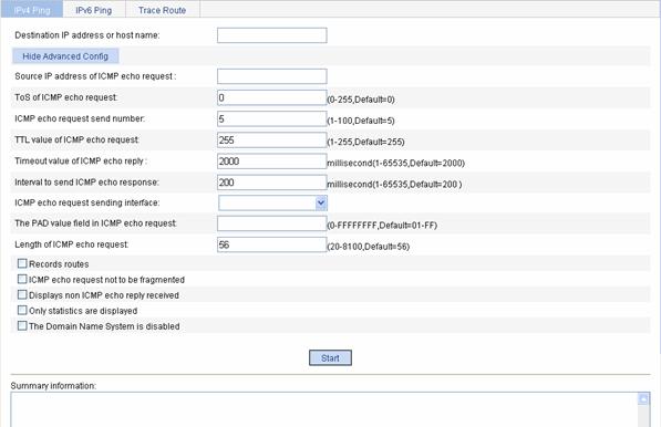
After the above configuration, type in the IPv4 address or host name of the destination device in the Destination IP address or host name box, and set the advanced parameters for the IPv4 ping operation. Then click Start to execute the ping command, and you can see the result in the Summary box.
IPv6 ping
Select Diagnostic Tools > Ping from the navigation tree to enter the IPv6 ping configuration page. Then click Display Advanced Config to display the configurations of the advanced parameters of IPv6 ping operation, as shown in Figure 9-2.
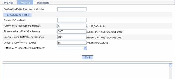
After the above configuration, type in the IPv6 address or host name of the destination device in the Destination IP address or host name box, and set the advanced parameters for the IPv6 ping operation. Then click Start to execute the ping command, and you can see the result in the Summary box.
Trace Route Operation
![]()
The Web interface supports trace route on IPv4 addresses only.
Select Diagnostic Tools > Trace Route from the navigation tree, and click the Trace Route tab to enter the Trace Route configuration page, as shown in Figure 9-3.
Figure 9-3 Trace Route configuration page
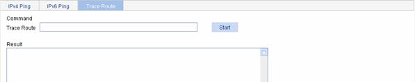
After the above configuration, type in the destination IP address, and click Start to execute the trace route command, and you can see the result in the Summary box.