- Table of Contents
-
- 03-Typical Configuration Example
- 01-H3C_AAA_Configuration_Examples
- 02-H3C_ACL_Configuration_Examples
- 03-H3C_ATM_Configuration_Examples
- 04-H3C_IGMP_Configuration_Examples
- 05-H3C_IP_Source_Guard_Configuration_Examples
- 06-H3C_Ethernet_OAM_Configuration_Examples
- 07-H3C_NQA_Configuration_Examples
- 08-H3C_QinQ_Configuration_Examples
- 09-H3C_OSPF_Configuration_Examples
- 10-H3C_MPLS_TE_Configuration_Examples
- 11-H3C_OpenFlow_Configuration_Examples
- 12-H3C_NAT_Configuration_Examples
- 13-H3C_RBAC_Configuration_Examples
- 14-H3C_IRF_Configuration_Examples
- 15-H3C_POS_Interface_Configuration_Examples
- 16-H3C_CPOS_Interface_Configuration_Examples
- 17-H3C_DHCP_Relay_Redundancy_Configuration_Examples
- 18-H3C_DLDP_Configuration_Examples
- 19-H3C_IS-IS_Configuration_Examples
- 20-H3C_MPLS_L3VPN_Configuration_Examples
- 21-H3C_SSH_Configuration_Examples
- 22-H3C_Login_Management_Configuration_Examples
- 23-H3C_SNMP_Configuration_Examples
- 24-H3C_Priority_Marking_and_Queue_Scheduling_Configuration_Examples
- 25-H3C_Multicast_VPN_Configuration_Examples
- 26-H3C_BGP_Configuration_Examples
- 27-H3C_HoVPN_Configuration_Examples
- 28-H3C_L2TP_Configuration_Examples
- 29-H3C_VRRP_Configuration_Examples
- 30-H3C_Traffic_Filtering_Configuration_Examples
- 31-H3C_Samplers_and_IPv4_NetStream_Configuration_Examples
- 32-H3C_Software_Upgrade_Examples
- 33-H3C_MPLS_L2VPN_Configuration_Examples
- 34-H3C_NetStream_Configuration_Examples
- 35-H3C_Policy-Based_Routing_Configuration_Examples
- 36-H3C_Traffic_Policing_Configuration_Examples
- 37-H3C_BFD_Configuration_Examples
- 38-H3C_OSPFv3_Configuration_Examples
- 39-H3C_VPLS_Configuration_Examples
- 40-H3C_GTS_and_Rate_Limiting_Configuration_Examples
- 41-H3C_IPv6_IS-IS_Configuration_Examples
- 42-H3C_MPLS OAM_Configuration_Examples
- 43-H3C_BGP_Route_Selection_Configuration_Examples
- 44-H3C_IS-IS_Route_Summarization_Configuration_Examples
- 45-H3C_SRv6 Configuration Examples
- 46-H3C_Attack_Protection_Configuration_Examples
- 47-H3C_OSPF_Multi-Process_Configuration_Examples
- 48-H3C_OSPF_with_Multi-Instance_Configuration_Examples
- 49-H3C_ARP_Attack_Protection_Configuration_Examples
- 50-H3C_DHCPv6_Server_and_DHCPv6_Prefix_Client_Configuration_Examples
- 51-Bidirectional NAT and NAT Server Configuration Examples
- 52-Bidirectional NAT and NAT Server With Easy IP Configuration Examples (Global NAT)
- 53-CE1 Interface Connection Configuration Examples
- 54-General QoS Configuration Examples
- 55-GRE Tunnel Establishment Using OSPF Configuration Examples
- 56-GRE Tunnel Establishment Using Static Routes Configuration Examples
- 57-Internal Users Accessing the External Network Configuration Examples
- 58-OSPF over IPsec for Overseas Branch Access Configuration Examples
- 59-QoS Configuration Examples for the Financial Industry
- Related Documents
-
| Title | Size | Download |
|---|---|---|
| 57-Internal Users Accessing the External Network Configuration Examples | 119.13 KB |
Example: Configuring internal users to use different traffic redirection policies and different NAT address groups to access the external network
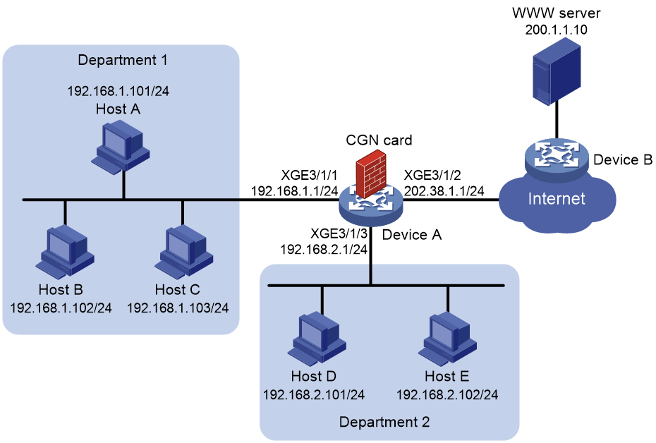
Network configuration
As shown in Figure 1, the hosts access the Internet after NAT on Device A. A CGN card is installed on slot 2 of Device A, which provides address translation. Department 1 uses private network 192.168.1.0/24 and Department 2 uses private network 192.168.2.0/24.
Configure outbound NAT to meet the following requirements:
· Department 1 uses IP addresses in address range 202.38.1.100 to 202.38.1.200 to access the Internet and NO-PAT is used for address translation. A NAT address can be assigned to only one private IP address for address translation at the same time.
· Department 2 uses IP addresses in address range 202.38.1.2 to 202.38.1.5 to access the Internet and PAT is used for address translation. A NAT address can be assigned to multiple private IP addresses for address translation at the same time.
Procedures
Configuring Device A
1. Specify IPv4 addresses for the interfaces on Device A.
<DeviceA> system-view
[DeviceA] interface ten-gigabitethernet 3/1/1
[DeviceA-Ten-GigabitEthernet3/1/1] ip address 192.168.1.1 255.255.255.0
[DeviceA-Ten-GigabitEthernet3/1/1] quit
[DeviceA] interface ten-gigabitethernet 3/1/2
[DeviceA-Ten-GigabitEthernet3/1/2] ip address 202.38.1.1 255.255.255.0
[DeviceA-Ten-GigabitEthernet3/1/2] quit
[DeviceA] interface ten-gigabitethernet 3/1/3
[DeviceA-Ten-GigabitEthernet3/1/3] ip address 192.168.2.1 255.255.255.0
[DeviceA-Ten-GigabitEthernet3/1/3] quit
2. Configure a failover group:
# Specify the CGN card in slot 2 as the primary node in failover group cgn1.
[DeviceA] failover group cgn1 id 1
[DeviceA-failover-group-cgn] bind slot 2 primary
[DeviceA-failover-group-cgn] quit
3. # Create service instance group 1 and associate it with failover group cgn1.
[DeviceA] service-instance-group 1
[DeviceA-service-instance-group 1] failover-group cgn1
[DeviceA-service-instance-group 1] quit
4. Configure global NAT:
a. Configure an ACL:
# Configure ACL 3000 to identify packets from subnet 192.168.1.0/24.
[DeviceA] acl advanced 3000
[DeviceA-acl-ipv4-adv-3000] rule 5 permit ip source 192.168.1.0 0.0.0.255
[DeviceA-acl-ipv4-adv-3000] quit
# Configure ACL 3001 to identify packets from subnet 192.168.2.0/24.
[DeviceA] acl advanced 3001
[DeviceA-acl-ipv4-adv-3001] rule 5 permit ip source 192.168.2.0 0.0.0.255
[DeviceA-acl-ipv4-adv-3001] quit
b. Configure an address group:
# Configure address group 0 and add an address range from 202.38.1.100 to 202.38.1.200.
[DeviceA] nat address-group 0
[DeviceA-address-group-0] address 202.38.1.100 202.38.1.200
[DeviceA-address-group-0] quit
# Configure address group 1 and add an address range from 202.38.1.2 to 202.38.1.5.
[DeviceA] nat address-group 1
[DeviceA-address-group-1] address 202.38.1.2 202.38.1.5
[DeviceA-address-group-1] quit
c. Configure a NAT instance:
# Create a NAT instance named a with ID 1.
[DeviceA] nat instance a id 1
# Associate NAT instance a with service instance group 1.
[DeviceA-nat-instance-a] service-instance-group 1
# Configure an outbound NO-PAT rule to translate the source addresses of outgoing packets permitted by ACL 3000 into the addresses in address group 0.
[DeviceA-nat-instance-a] nat outbound 3000 address-group 0 no-pat
# Configure an outbound PAT rule to translate the source addresses of outgoing packets permitted by ACL 3001 into the addresses in address group 1.
[DeviceA-nat-instance-a] nat outbound 3001 address-group 1
[Device-nat-instance-a] quit
5. Configure a QoS policy to redirect traffic to the NAT instance for address translation:
# Configure traffic class cgn and traffic behavior cgn.
[DeviceA] traffic classifier cgn operator or
[DeviceA-classifier-cgn] if-match acl 3000
[DeviceA-classifier-cgn] if-match acl 3001
[DeviceA-classifier-cgn] quit
[DeviceA] traffic behavior cgn
[DeviceA-behavior-cgn] bind nat-instance a
[DeviceA-behavior-cgn] quit
# Create QoS policy cgn and associate the traffic class with the traffic behavior.
[DeviceA] qos policy cgn
[DeviceA-qospolicy-cgn] classifier cgn behavior cgn
[DeviceA-qospolicy-cgn] quit
# Apply the QoS policy to the inbound traffic on Ten-GigabitEthernet 3/1/1.
[DeviceA] interface ten-gigabitethernet 3/1/1
[DeviceA-Ten-GigabitEthernet3/1/1] qos apply policy cgn inbound
[DeviceA-Ten-GigabitEthernet3/1/1] quit
# Apply the QoS policy to the inbound traffic on Ten-GigabitEthernet 3/1/3.
[DeviceA] interface ten-gigabitethernet 3/1/3
[DeviceA-Ten-GigabitEthernet3/1/3] qos apply policy cgn inbound
[DeviceA-Ten-GigabitEthernet3/1/3] quit
Configuring hosts
Make sure each host and Device A can reach each other.
Verifying the configuration
# Enter the IP address of the WWW server in the address bar of the Web browser on Host A. Display NAT session information generated on Device A when Host A accesses the WWW server.
[DeviceA] display nat session verbose
Slot 2:
Initiator:
Source IP/port: 192.168.1.101/4481
Destination IP/port: 200.1.1.10/80
DS-Lite tunnel peer: -
VPN instance/VLAN ID/Inline ID: -/-/-
Protocol: TCP(6)
Inbound interface: Ten-GigabitEthernet3/1/1
Responder:
Source IP/port: 200.1.1.10/80
Destination IP/port: 202.38.1.2/1029
DS-Lite tunnel peer: -
VPN instance/VLAN ID/Inline ID: -/-/-
Protocol: TCP(6)
Inbound interface: Ten-GigabitEthernet3/1/2
State: TCP_ESTABLISHED
Application: HTTP
Role: Master
Failover group ID: 1
Start time: 2023-02-13 15:50:33 TTL: 3583s
Initiator->Responder: 0 packets 0 bytes
Responder->Initiator: 0 packets 0 bytes
Total sessions found: 1
# Display information about NAT NO-PAT entries generated on Device A when Host A accesses the WWW server.
[DeviceA] display nat no-pat
Slot 2:
Local IP: 192.168.1.101
Global IP: 202.38.1.2
Reversible: N
Type : Outbound
Total entries found: 1
# Enter the IP address of the WWW server in the address bar of the Web browser on Host D. Display NAT session information generated on Device A when Host D accesses the WWW server.
[DeviceA] display nat session verbose
Slot 2:
Initiator:
Source IP/port: 192.168.2.101/33283
Destination IP/port: 200.1.1.10/80
DS-Lite tunnel peer: -
VPN instance/VLAN ID/Inline ID: -/-/-
Protocol: TCP(6)
Inbound interface: Ten-GigabitEthernet3/1/3
Responder:
Source IP/port: 200.1.1.10/80
Destination IP/port: 202.38.1.188/1026
DS-Lite tunnel peer: -
VPN instance/VLAN ID/Inline ID: -/-/-
Protocol: TCP(6)
Inbound interface: Ten-GigabitEthernet3/1/2
State: TCP_ESTABLISHED
Application: HTTP
Role: Master
Failover group ID: 1
Start time: 2023-02-13 15:54:16 TTL: 3588s
Initiator->Responder: 0 packets 0 bytes
Responder->Initiator: 0 packets 0 bytes
Total sessions found: 1
Configuration files
Device A:
#
failover group cgn1 id 1
bind slot 2 primary
#
service-instance-group 1
failover-group cgn1
#
nat instance a id 1
service-instance-group 1
nat outbound 3000 address-group 0 no-pat
nat outbound 3001 address-group 1
#
traffic classifier cgn operator or
if-match acl 3000
if-match acl 3001
#
traffic behavior cgn
bind nat-instance a
#
qos policy cgn
classifier cgn behavior cgn
#
interface Ten-GigabitEthernet3/1/1
ip address 192.168.1.1 255.255.255.0
qos apply policy cgn inbound
#
interface Ten-GigabitEthernet3/1/2
ip address 202.38.1.1 255.255.255.0
#
interface Ten-GigabitEthernet3/1/3
ip address 192.168.2.1 255.255.255.0
qos apply policy cgn inbound
#
nat address-group 0
address 202.38.1.2 202.38.1.5
#
nat address-group 1
address 202.38.1.100 202.38.1.200
#
acl advanced 3000
rule 5 permit ip source 192.168.1.0 0.0.0.255
#
acl advanced 3001
rule 5 permit ip source 192.168.2.0 0.0.0.255
#
Example: Configuring internal users to access external Web servers by using NAT addresses
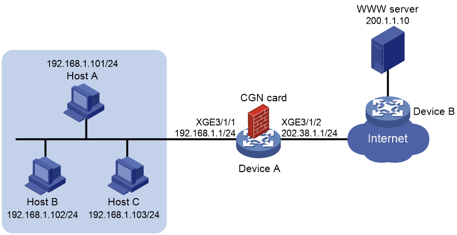
Network configuration
As shown in Figure 1, the hosts access the Internet after NAT on Device A. A CGN card is installed on slot 2 of Device A, which provides address translation. The company uses private IP addresses on network 192.168.1.0/24 and public IP addresses 202.38.1.2 and 202.38.1.3.
Configure outbound NAT to meet the following requirements:
· Only hosts on subnet 192.168.1.0/24 can access the Internet.
· Device A performs many-to-many address translation.
Figure 2 Network diagram
Procedures
Configuring Device A
1. Specify IPv4 addresses for the interfaces on Device A.
<DeviceA> system-view
[DeviceA] interface ten-gigabitethernet 3/1/1
[DeviceA-Ten-GigabitEthernet3/1/1] ip address 192.168.1.1 255.255.255.0
[DeviceA-Ten-GigabitEthernet3/1/1] quit
[DeviceA] interface ten-gigabitethernet 3/1/2
[DeviceA-Ten-GigabitEthernet3/1/2] ip address 202.38.1.1 255.255.255.0
[DeviceA-Ten-GigabitEthernet3/1/2] quit
2. Configure a failover group:
# Specify the CGN card in slot 2 as the primary node in failover group cgn1.
[DeviceA] failover group cgn1 id 1
[DeviceA-failover-group-cgn] bind slot 2 primary
[DeviceA-failover-group-cgn] quit
3. Create service instance group 1 and associate it with failover group cgn1.
[DeviceA] service-instance-group 1
[DeviceA-service-instance-group 1] failover-group cgn1
[DeviceA-service-instance-group 1] quit
4. Configure global NAT:
a. Configure an ACL:
# Configure ACL 3000 to identify packets from subnet 192.168.1.0/24.
[DeviceA] acl advanced 3000
[DeviceA-acl-ipv4-adv-3000] rule 5 permit ip source 192.168.1.0 0.0.0.255
[DeviceA-acl-ipv4-adv-3000] quit
b. Configure an address group:
# Configure address group 0 and add an address range from 202.38.1.2 to 202.38.1.3.
[DeviceA] nat address-group 0
[DeviceA-address-group-0] address 202.38.1.2 202.38.1.3
[DeviceA-address-group-0] quit
c. Configure a NAT instance:
# Create a NAT instance named a with ID 1.
[DeviceA] nat instance a id 1
# Associate NAT instance a with service instance group 1.
[DeviceA-nat-instance-a] service-instance-group 1
# Configure outbound dynamic NAT to use NAT address group 0 to translate packets permitted by ACL 3000.
[DeviceA-nat-instance-a] nat outbound 3000 address-group 0
[DeviceA-nat-instance-a] quit
5. Configure a QoS policy to redirect traffic to the NAT instance for address translation:
# Configure traffic class cgn and traffic behavior cgn.
[DeviceA] traffic classifier cgn operator and
[DeviceA-classifier-cgn] if-match acl 3000
[DeviceA-classifier-cgn] quit
[DeviceA] traffic behavior cgn
[DeviceA-behavior-cgn] bind nat-instance a
[DeviceA-behavior-cgn] quit
# Create QoS policy cgn and associate the traffic class with the traffic behavior.
[DeviceA] qos policy cgn
[DeviceA-qospolicy-cgn] classifier cgn behavior cgn
[DeviceA-qospolicy-cgn] quit
# Apply the QoS policy to the inbound traffic on Ten-GigabitEthernet3/1/1.
[DeviceA] interface ten-gigabitethernet 3/1/1
[DeviceA-Ten-GigabitEthernet3/1/1] qos apply policy cgn inbound
[DeviceA-Ten-GigabitEthernet3/1/1] quit
Configuring hosts
Make sure each host and Device A can reach each other.
Verifying the configuration
# Enter the IP address of the WWW server in the address bar of the Web browser on Host A. Display NAT session information generated on Device A when Host A accesses the WWW server.
[DeviceA] display nat session verbose
Slot 2:
Initiator:
Source IP/port: 192.168.1.101/4481
Destination IP/port: 200.1.1.10/80
DS-Lite tunnel peer: -
VPN instance/VLAN ID/Inline ID: -/-/-
Protocol: TCP(6)
Inbound interface: Ten-GigabitEthernet3/1/1
Responder:
Source IP/port: 200.1.1.10/80
Destination IP/port: 202.38.1.2/1029
DS-Lite tunnel peer: -
VPN instance/VLAN ID/Inline ID: -/-/-
Protocol: TCP(6)
Inbound interface: Ten-GigabitEthernet3/1/2
State: TCP_ESTABLISHED
Application: HTTP
Role: Master
Failover group ID: 1
Start time: 2023-02-05 16:15:28 TTL: 3591s
Initiator->Responder: 0 packets 0 bytes
Responder->Initiator: 0 packets 0 bytes
Total sessions found: 1
Configuration files
Device A:
#
failover group cgn1 id 1
bind slot 2 primary
#
service-instance-group 1
failover-group cgn1
#
nat instance a id 1
service-instance-group 1
nat outbound 3000 address-group 0
#
traffic classifier cgn operator and
if-match acl 3000
#
traffic behavior cgn
bind nat-instance a
#
qos policy cgn
classifier cgn behavior cgn
#
interface Ten-GigabitEthernet3/1/1
ip address 192.168.1.1 255.255.255.0
qos apply policy cgn inbound
#
interface Ten-GigabitEthernet3/1/2
ip address 202.38.1.1 255.255.255.0
#
nat address-group 0
address 202.38.1.2 202.38.1.3
#
acl advanced 3000
rule 5 permit ip source 192.168.1.0 0.0.0.255
#