- Table of Contents
-
- 03-Typical Configuration Example
- 01-H3C_AAA_Configuration_Examples
- 02-H3C_ACL_Configuration_Examples
- 03-H3C_ATM_Configuration_Examples
- 04-H3C_IGMP_Configuration_Examples
- 05-H3C_IP_Source_Guard_Configuration_Examples
- 06-H3C_Ethernet_OAM_Configuration_Examples
- 07-H3C_NQA_Configuration_Examples
- 08-H3C_QinQ_Configuration_Examples
- 09-H3C_OSPF_Configuration_Examples
- 10-H3C_MPLS_TE_Configuration_Examples
- 11-H3C_OpenFlow_Configuration_Examples
- 12-H3C_NAT_Configuration_Examples
- 13-H3C_RBAC_Configuration_Examples
- 14-H3C_IRF_Configuration_Examples
- 15-H3C_POS_Interface_Configuration_Examples
- 16-H3C_CPOS_Interface_Configuration_Examples
- 17-H3C_DHCP_Relay_Redundancy_Configuration_Examples
- 18-H3C_DLDP_Configuration_Examples
- 19-H3C_IS-IS_Configuration_Examples
- 20-H3C_MPLS_L3VPN_Configuration_Examples
- 21-H3C_SSH_Configuration_Examples
- 22-H3C_Login_Management_Configuration_Examples
- 23-H3C_SNMP_Configuration_Examples
- 24-H3C_Priority_Marking_and_Queue_Scheduling_Configuration_Examples
- 25-H3C_Multicast_VPN_Configuration_Examples
- 26-H3C_BGP_Configuration_Examples
- 27-H3C_HoVPN_Configuration_Examples
- 28-H3C_L2TP_Configuration_Examples
- 29-H3C_VRRP_Configuration_Examples
- 30-H3C_Traffic_Filtering_Configuration_Examples
- 31-H3C_Samplers_and_IPv4_NetStream_Configuration_Examples
- 32-H3C_Software_Upgrade_Examples
- 33-H3C_MPLS_L2VPN_Configuration_Examples
- 34-H3C_NetStream_Configuration_Examples
- 35-H3C_Policy-Based_Routing_Configuration_Examples
- 36-H3C_Traffic_Policing_Configuration_Examples
- 37-H3C_BFD_Configuration_Examples
- 38-H3C_OSPFv3_Configuration_Examples
- 39-H3C_VPLS_Configuration_Examples
- 40-H3C_GTS_and_Rate_Limiting_Configuration_Examples
- 41-H3C_IPv6_IS-IS_Configuration_Examples
- 42-H3C_MPLS OAM_Configuration_Examples
- 43-H3C_BGP_Route_Selection_Configuration_Examples
- 44-H3C_IS-IS_Route_Summarization_Configuration_Examples
- 45-H3C_SRv6 Configuration Examples
- 46-H3C_Attack_Protection_Configuration_Examples
- 47-H3C_OSPF_Multi-Process_Configuration_Examples
- 48-H3C_OSPF_with_Multi-Instance_Configuration_Examples
- 49-H3C_ARP_Attack_Protection_Configuration_Examples
- 50-H3C_DHCPv6_Server_and_DHCPv6_Prefix_Client_Configuration_Examples
- 51-Bidirectional NAT and NAT Server Configuration Examples
- 52-Bidirectional NAT and NAT Server With Easy IP Configuration Examples (Global NAT)
- 53-CE1 Interface Connection Configuration Examples
- 54-General QoS Configuration Examples
- 55-GRE Tunnel Establishment Using OSPF Configuration Examples
- 56-GRE Tunnel Establishment Using Static Routes Configuration Examples
- 57-Internal Users Accessing the External Network Configuration Examples
- 58-OSPF over IPsec for Overseas Branch Access Configuration Examples
- 59-QoS Configuration Examples for the Financial Industry
- Related Documents
-
| Title | Size | Download |
|---|---|---|
| 52-Bidirectional NAT and NAT Server With Easy IP Configuration Examples (Global NAT) | 77.51 KB |
Example: Configuring bidirectional NAT and NAT Server with easy IP
Network configuration
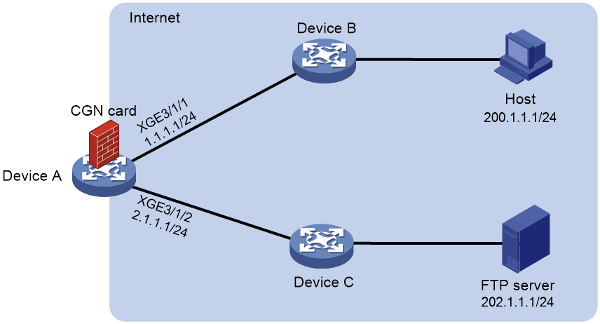
As shown in Figure 1, Device A acts as an egress gateway. A CGN card is installed on slot 2 of Device A, which provides address translation. For security, configure service traffic between the host and FTP server to be forwarded by Device A:
· The IP address used by the FTP server for providing services is the primary IP address of Loopback 10 on Device A.
· The source IP address of packets sent from the host to the FTP server is IP address 22.2.2.2 in NAT address group 1.
Bidirectional NAT enables the host and the FTP server to communicate with each other without perceiving each other's real IP address on the public network.
Analysis
To hide the real IP addresses of the host and FTP server on the public network, perform the following tasks:
· Configure destination address translation and set the IP address used by the FTP server for providing services to the IP address of Loopback 10.
· Configure source address translation. Configure Device A to translate the source IP address of packets sent from the host to the FTP server into the IP address in NAT address group 1.
Procedures
Configuring Device A
1. Specify IPv4 addresses for the interfaces on Device A.
<DeviceA> system-view
[DeviceA] interface ten-gigabitethernet 3/1/1
[DeviceA-Ten-GigabitEthernet3/1/1] ip address 1.1.1.1 255.255.255.0
[DeviceA-Ten-GigabitEthernet3/1/1] quit
[DeviceA] interface ten-gigabitethernet 3/1/2
[DeviceA-Ten-GigabitEthernet3/1/2] ip address 2.1.1.1 255.255.255.0
[DeviceA-Ten-GigabitEthernet3/1/2] quit
[DeviceA] interface loopback 10
[DeviceA-LoopBack10] ip address 11.1.1.1 255.255.255.0
[DeviceA-LoopBack10] quit
2. Configure an ACL:
# Configure ACL 3001 to permit all packets.
[DeviceA] acl advanced 3001
[DeviceA-acl-ipv4-adv-3001] rule 1 permit ip source any
[DeviceA-acl-ipv4-adv-3001] quit
3. Configure a failover group:
# Specify the CGN card in slot 2 as the primary node in failover group cgn1.
[DeviceA] failover group cgn1 id 1
[DeviceA-failover-group-cgn] bind slot 2 primary
[DeviceA-failover-group-cgn] quit
4. Create service instance group 1 and associate it with failover group cgn1.
[DeviceA] service-instance-group 1
[DeviceA-service-instance-group 1] failover-group cgn1
[DeviceA-service-instance-group 1] quit
5. Configure a NAT address group:
# Create address group 1 and add address 22.2.2.2 to the group.
[DeviceA] nat address-group 1
[DeviceA-address-group-1] address 22.2.2.2 22.2.2.2
[DeviceA-address-group-1] quit
6. Configure a NAT instance:
# Create a NAT instance named a with ID 1.
[DeviceA] nat instance a id 1
# Associate NAT instance a with service instance group 1.
[DeviceA-nat-instance-a] service-instance-group 1
# Configure outbound dynamic NAT to use NAT address group 1 to translate packets permitted by ACL 3001.
[DeviceA-nat-instance-a] nat outbound 3001 address-group 1
# Configure a NAT server mapping to translate packets with the primary IP address of Loopback 10 as the destination address and port 21. After address translation, the destination IP address is 202.1.1.1 and the port number is 21.
[DeviceA-nat-instance-a] nat server protocol tcp global interface loopback 10 21 inside 202.1.1.1 ftp
[DeviceA-nat-instance-a] quit
7. Configure a QoS policy to redirect traffic to the NAT instance for address translation:
# Configure traffic class a and traffic behavior a.
[DeviceA] traffic classifier a operator and
[DeviceA-classifier-a] if-match acl 3001
[DeviceA-classifier-a] quit
[DeviceA] traffic behavior cgn
[DeviceA-behavior-a] bind nat-instance a
[DeviceA-behavior-a] quit
# Create QoS policy a and associate the traffic class with the traffic behavior.
[DeviceA] qos policy a
[DeviceA-qospolicy-a] classifier a behavior a
[DeviceA-qospolicy-a] quit
# Apply the QoS policy to the inbound traffic on Ten-GigabitEthernet3/1/1 and Ten-GigabitEthernet3/1/2.
[DeviceA] interface ten-gigabitethernet 3/1/1
[DeviceA-Ten-GigabitEthernet3/1/1] qos apply policy a inbound
[DeviceA-Ten-GigabitEthernet3/1/1] quit
[DeviceA] interface ten-gigabitethernet 3/1/2
[DeviceA-Ten-GigabitEthernet3/1/2] qos apply policy a inbound
[DeviceA-Ten-GigabitEthernet3/1/2] quit
Configuring the host
Make sure the host and Device A can reach each other.
Verifying the configuration
# Access the FTP server by using IP address 11.1.1.1 on the host. Display NAT session information generated on Device A when Host A accesses the FTP server.
[DeviceA] display nat session verbose
Slot 3:
Initiator:
Source IP/port: 200.1.1.1/30929
Destination IP/port: 11.1.1.1/21
DS-Lite tunnel peer: -
VPN instance/VLAN ID/Inline ID: -/-/-
Protocol: TCP(6)
Inbound interface: GigabitEthernet0/0
Responder:
Source IP/port: 202.1.1.1/21
Destination IP/port: 22.2.2.2/1025
DS-Lite tunnel peer: -
VPN instance/VLAN ID/Inline ID: -/-/-
Protocol: TCP(6)
Inbound interface: GigabitEthernet0/1
State: TCP_ESTABLISHED
Application: FTP
Role: Master
Failover group ID: 1
Start time: 2023-03-07 08:20:14 TTL: 3598s
Initiator->Responder: 0 packets 0 bytes
Responder->Initiator: 0 packets 0 bytes
Total sessions found: 1
The output shows that the host (session initiator) regards the IP address of the FTP server as 11.1.1.1 and the FTP server (session responder) regards the IP address of the host as 22.2.2.2. They cannot perceive each other's real IP address on the public network.
Configuration files
Device A:
#
interface LoopBack10
ip address 11.1.1.1 255.255.255.0
#
interface Ten-GigabitEthernet3/1/1
ip address 1.1.1.1 255.255.255.0
qos apply policy a inbound
#
interface Ten-GigabitEthernet3/1/2
ip address 2.1.1.1 255.255.255.0
qos apply policy a inbound
#
acl advanced 3001
rule 1 permit ip
#
failover group cgn1 id 1
bind slot 2 primary
#
service-instance-group 1
failover-group cgn1
#
nat instance a id 1
service-instance-group 1
nat outbound 3001 address-group 1
nat server protocol tcp global interface LoopBack10 21 inside 202.1.1.1 21
#
traffic classifier a operator and
if-match acl 3001
#
traffic behavior a
bind nat-instance a
#
qos policy a
classifier a behavior a
#
nat address-group 1
address 22.2.2.2 22.2.2.2
#