- Table of Contents
-
- 03-Typical Configuration Example
- 01-H3C_AAA_Configuration_Examples
- 02-H3C_ACL_Configuration_Examples
- 03-H3C_ATM_Configuration_Examples
- 04-H3C_IGMP_Configuration_Examples
- 05-H3C_IP_Source_Guard_Configuration_Examples
- 06-H3C_Ethernet_OAM_Configuration_Examples
- 07-H3C_NQA_Configuration_Examples
- 08-H3C_QinQ_Configuration_Examples
- 09-H3C_OSPF_Configuration_Examples
- 10-H3C_MPLS_TE_Configuration_Examples
- 11-H3C_OpenFlow_Configuration_Examples
- 12-H3C_NAT_Configuration_Examples
- 13-H3C_RBAC_Configuration_Examples
- 14-H3C_IRF_Configuration_Examples
- 15-H3C_POS_Interface_Configuration_Examples
- 16-H3C_CPOS_Interface_Configuration_Examples
- 17-H3C_DHCP_Relay_Redundancy_Configuration_Examples
- 18-H3C_DLDP_Configuration_Examples
- 19-H3C_IS-IS_Configuration_Examples
- 20-H3C_MPLS_L3VPN_Configuration_Examples
- 21-H3C_SSH_Configuration_Examples
- 22-H3C_Login_Management_Configuration_Examples
- 23-H3C_SNMP_Configuration_Examples
- 24-H3C_Priority_Marking_and_Queue_Scheduling_Configuration_Examples
- 25-H3C_Multicast_VPN_Configuration_Examples
- 26-H3C_BGP_Configuration_Examples
- 27-H3C_HoVPN_Configuration_Examples
- 28-H3C_L2TP_Configuration_Examples
- 29-H3C_VRRP_Configuration_Examples
- 30-H3C_Traffic_Filtering_Configuration_Examples
- 31-H3C_Samplers_and_IPv4_NetStream_Configuration_Examples
- 32-H3C_Software_Upgrade_Examples
- 33-H3C_MPLS_L2VPN_Configuration_Examples
- 34-H3C_NetStream_Configuration_Examples
- 35-H3C_Policy-Based_Routing_Configuration_Examples
- 36-H3C_Traffic_Policing_Configuration_Examples
- 37-H3C_BFD_Configuration_Examples
- 38-H3C_OSPFv3_Configuration_Examples
- 39-H3C_VPLS_Configuration_Examples
- 40-H3C_GTS_and_Rate_Limiting_Configuration_Examples
- 41-H3C_IPv6_IS-IS_Configuration_Examples
- 42-H3C_MPLS OAM_Configuration_Examples
- 43-H3C_BGP_Route_Selection_Configuration_Examples
- 44-H3C_IS-IS_Route_Summarization_Configuration_Examples
- 45-H3C_SRv6 Configuration Examples
- 46-H3C_Attack_Protection_Configuration_Examples
- 47-H3C_OSPF_Multi-Process_Configuration_Examples
- 48-H3C_OSPF_with_Multi-Instance_Configuration_Examples
- 49-H3C_ARP_Attack_Protection_Configuration_Examples
- 50-H3C_DHCPv6_Server_and_DHCPv6_Prefix_Client_Configuration_Examples
- 51-Bidirectional NAT and NAT Server Configuration Examples
- 52-Bidirectional NAT and NAT Server With Easy IP Configuration Examples (Global NAT)
- 53-CE1 Interface Connection Configuration Examples
- 54-General QoS Configuration Examples
- 55-GRE Tunnel Establishment Using OSPF Configuration Examples
- 56-GRE Tunnel Establishment Using Static Routes Configuration Examples
- 57-Internal Users Accessing the External Network Configuration Examples
- 58-OSPF over IPsec for Overseas Branch Access Configuration Examples
- 59-QoS Configuration Examples for the Financial Industry
- Related Documents
-
| Title | Size | Download |
|---|---|---|
| 51-Bidirectional NAT and NAT Server Configuration Examples | 78.71 KB |
Example: Configuring bidirectional NAT and NAT Server
Network configuration
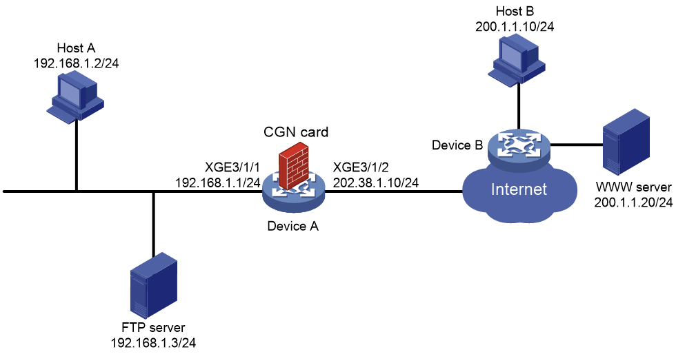
As shown in Figure 1, Host A accesses the Internet after NAT on Device A. A CGN card is installed on slot 2 of Device A, which provides address translation. The company uses private IP addresses on network 192.168.1.0/24 and public IP address 202.38.1.100 to provide FTP services.
Configure bidirectional NAT and NAT Server to meet the following requirements:
· Both Host A and Host B can access the FTP server by using IP address 202.38.1.100 and port 21.
· Only users on subnet 192.168.1.0/24 can access the Internet by using public IP addresses 202.38.1.2 and 202.38.1.3.
Procedures
Configuring Device A
1. Specify IPv4 addresses for the interfaces on Device A.
<DeviceA> system-view
[DeviceA] interface ten-gigabitethernet 3/1/1
[DeviceA-Ten-GigabitEthernet3/1/1] ip address 192.168.1.1 255.255.255.0
[DeviceA-Ten-GigabitEthernet3/1/1] quit
[DeviceA] interface ten-gigabitethernet 3/1/2
[DeviceA-Ten-GigabitEthernet3/1/2] ip address 202.38.1.10 255.255.255.0
[DeviceA-Ten-GigabitEthernet3/1/2] quit
2. Configure an ACL:
# Configure ACL 3002 to permit all packets.
[DeviceA] acl advanced 3002
[DeviceA-acl-ipv4-adv-3002] rule 5 permit ip source any
[DeviceA-acl-ipv4-adv-3002] quit
3. Configure a failover group:
# Specify the CGN card in slot 2 as the primary node in failover group cgn1.
[DeviceA] failover group cgn1 id 1
[DeviceA-failover-group-cgn] bind slot 2 primary
[DeviceA-failover-group-cgn] quit
4. Create service instance group 1 and associate it with failover group cgn1.
[[DeviceA] service-instance-group 1
[DeviceA-service-instance-group 1] failover-group cgn1
[DeviceA-service-instance-group 1] quit
5. Configure an address group:
# Configure address group 0 and add an address range from 202.38.1.2 to 202.38.1.3.
[DeviceA] nat address-group 0
[DeviceA-address-group-0] address 202.38.1.2 202.38.1.3
[DeviceA-address-group-0] quit
6. Configure a NAT instance:
# Create a NAT instance named a with ID 1.
[DeviceA] nat instance a id 1
# Associate NAT instance a with service instance group 1.
[DeviceA-nat-instance-a] service-instance-group 1
# Configure outbound dynamic NAT to use NAT address group 0 to translate packets permitted by ACL 3002.
[DeviceA-nat-instance-a] nat outbound 3002 address-group 0
# Configure a NAT server mapping to allow external users to access the FTP server by using the address 202.38.1.100 and port 21.
[DeviceA-nat-instance-a] nat server protocol tcp global 202.38.1.100 21 inside 192.168.1.3 ftp
[Device-nat-instance-a] quit
7. Configure a QoS policy to redirect traffic to the NAT instance for address translation:
# Configure traffic class cgn and traffic behavior cgn.
[DeviceA] traffic classifier cgn operator and
[DeviceA-classifier-cgn] if-match acl 3002
[DeviceA-classifier-cgn] quit
[DeviceA] traffic behavior cgn
[DeviceA-behavior-cgn] bind nat-instance a
[DeviceA-behavior-cgn] quit
# Create QoS policy cgn and associate the traffic class with the traffic behavior.
[DeviceA] qos policy cgn
[DeviceA-qospolicy-cgn] classifier cgn behavior cgn
[DeviceA-qospolicy-cgn] quit
# Apply the QoS policy to the inbound traffic on Ten-GigabitEthernet3/1/1.
[DeviceA] interface ten-gigabitethernet 3/1/1
[DeviceA-Ten-GigabitEthernet3/1/1] qos apply policy cgn inbound
[DeviceA-Ten-GigabitEthernet3/1/1] quit
Configuring Host B
Make sure Host B and Device A can reach each other.
Verifying the configuration
# Access the FTP server by using IP address 202.38.1.100 and port 21 on Host A. Display NAT session information generated on Device A when Host A accesses the FTP server.
[DeviceA] display nat session verbose
Slot 2:
Initiator:
Source IP/port: 192.168.1.2/22213
Destination IP/port: 202.38.1.100/21
DS-Lite tunnel peer: -
VPN instance/VLAN ID/Inline ID: -/-/-
Protocol: TCP(6)
Inbound interface: Ten-GigabitEthernet3/1/1
Responder:
Source IP/port: 192.168.1.3/21
Destination IP/port: 202.38.1.3/1024
DS-Lite tunnel peer: -
VPN instance/VLAN ID/Inline ID: -/-/-
Protocol: TCP(6)
Inbound interface: Ten-GigabitEthernet3/1/1
State: TCP_ESTABLISHED
Application: FTP
Role: Master
Failover group ID: 1
Start time: 2023-03-06 15:40:47 TTL: 3592s
Initiator->Responder: 0 packets 0 bytes
Responder->Initiator: 0 packets 0 bytes
Total sessions found: 1
# Enter the IP address of the WWW server in the address bar of the Web browser on Host A. Display NAT session information generated on Device A when Host A accesses the WWW server.
[DeviceA] display nat session verbose
Slot 2:
Initiator:
Source IP/port: 192.168.1.2/4481
Destination IP/port: 200.1.1.20/80
DS-Lite tunnel peer: -
VPN instance/VLAN ID/Inline ID: -/-/-
Protocol: TCP(6)
Inbound interface: Ten-GigabitEthernet3/1/1
Responder:
Source IP/port: 200.1.1.20/80
Destination IP/port: 202.38.1.2/1029
DS-Lite tunnel peer: -
VPN instance/VLAN ID/Inline ID: -/-/-
Protocol: TCP(6)
Inbound interface: Ten-GigabitEthernet3/1/2
State: TCP_ESTABLISHED
Application: HTTP
Role: Master
Failover group ID: 1
Start time: 2023-03-06 15:50:33 TTL: 3583s
Initiator->Responder: 0 packets 0 bytes
Responder->Initiator: 0 packets 0 bytes
Total sessions found: 1
# Access the FTP server by using IP address 202.38.1.100 and port 21 on Host B. Display NAT session information generated on Device A when Host B accesses the FTP server.
[DeviceA] display nat session verbose
Slot 2:
Initiator:
Source IP/port: 200.1.1.10/60738
Destination IP/port: 202.38.1.100/21
DS-Lite tunnel peer: -
VPN instance/VLAN ID/Inline ID: -/-/-
Protocol: TCP(6)
Inbound interface: Ten-GigabitEthernet3/1/2
Responder:
Source IP/port: 192.168.1.3/21
Destination IP/port: 200.1.1.10/60738
DS-Lite tunnel peer: -
VPN instance/VLAN ID/Inline ID: -/-/-
Protocol: TCP(6)
Inbound interface: Ten-GigabitEthernet3/1/1
State: TCP_ESTABLISHED
Application: FTP
Role: Master
Failover group ID: 1
Start time: 2023-03-06 15:55:40 TTL: 3593s
Initiator->Responder: 0 packets 0 bytes
Responder->Initiator: 0 packets 0 bytes
Total sessions found: 1
Configuration files
Device A:
#
failover group cgn1 id 1
bind slot 2 primary
#
service-instance-group 1
failover-group cgn1
#
nat instance a id 1
service-instance-group 1
nat outbound 3002 address-group 0
nat server protocol tcp global 202.38.1.100 21 inside 192.168.1.3 21
#
traffic classifier cgn operator and
if-match acl 3002
#
traffic behavior cgn
bind nat-instance a
#
qos policy cgn
classifier cgn behavior cgn
#
interface Ten-GigabitEthernet3/1/1
ip address 192.168.1.1 255.255.255.0
qos apply policy cgn inbound
#
interface Ten-GigabitEthernet3/1/2
ip address 202.38.1.10 255.255.255.0
#
nat address-group 0
address 202.38.1.2 202.38.1.3
#
acl advanced 3002
rule 5 permit ip