- Table of Contents
-
- 05-Comware 9 CLI-based configuration examples (AC+fit AP deployment)
- 01-HTTPS Login Configuration Examples
- 02-SSH Configuration Examples
- 03-License Management Configuration Examples
- 04-AP Association with the AC at Layer 2 Configuration Examples
- 05-AP Association with the AC at Layer 2 (IPv6) Configuration Examples
- 06-Auto AP Configuration Examples
- 07-AP Association with the AC at Layer 3 Configuration Examples
- 08-AP Association with the AC at Layer 3 (IPv6) Configuration Examples
- 09-WEP Encryption Configuration Examples
- 10-PSK Encryption Configuration Examples
- 11-WPA3-SAE PSK Encryption Configuration Examples
- 12-WLAN Access (IPv6) Configuration Examples
- 13-Policy-Based Forwarding with Dual Gateways Configuration Examples
- 14-Scheduled Configuration Deployment by AP Group Configuration Examples
- 15-Inter-AC Roaming with Static Client VLAN Allocation Configuration Examples
- 16-Service Template and Radio Binding Configuration Examples
- 17-Scheduled WLAN Access Services Configuration Examples
- 18-Local Portal Authentication Configuration Examples
- 19-HTTPS-Based Local Portal Authentication Configuration Examples
- 20-Remote Portal Authentication Configuration Examples
- 21-Local Portal Authentication through LDAP Server Configuration Examples
- 22-Local Portal Auth and SSID-based Auth Page Pushing Configuration Examples
- 23-Local Portal MAC-Trigger Authentication Configuration Examples
- 24-Portal MAC-Trigger Authentication Configuration Examples
- 25-Local Forwarding Mode and Local Portal MAC-Trigger Auth Configuration Examples
- 26-Local Portal Authentication (IPv6) Configuration Examples
- 27-Local Portal Authentication through LDAP Server (IPv6) Configuration Examples
- 28-Remote Portal Authentication (IPv6) Configuration Examples
- 29-Portal MAC-Trigger Authentication (IPv6) Configuration Example
- 30-Remote Portal Authentication with User Profile Authorization Configuration Examples
- 31-Portal Fail-Permit Configuration Examples
- 32-Local MAC Authentication Configuration Examples
- 33-Remote MAC Authentication Configuration Examples
- 34-Transparent Auth Through Remote MAC and Portal Auth Configuration Examples
- 35-Remote AP, Remote Portal, and MAC-Trigger Authentication Configuration Examples
- 36-MAC Authentication with Guest VLAN Assignment Configuration Examples
- 37-MAC Authentication with Guest VLAN Assignment (IPv6) Configuration Examples
- 38-Local MAC-And-802.1X Authentication Configuration Examples
- 39-Local 802.1X Authentication Configuration Examples
- 40-Local RADIUS-Based 802.1X Authentication in EAP Relay Mode Configuration Examples
- 41-Remote 802.1X Authentication Configuration Examples
- 42-Remote 802.1X Authentication (IPv6) Configuration Examples
- 43-Remote 802.1X Authentication in WPA3-Enterprise Mode Configuration Examples
- 44-802.1X Auth with ACL Assignment Through IMC Server Configuration Examples
- 45-802.1X Auth with User Profile Assignment Through IMC Server Configuration Examples
- 46-EAD Authentication Configuration Examples
- 47-EAD Authentication (IPv6) Configuration Examples
- 48-Local Forwarding Mode and Local Portal Authentication Configuration Examples
- 49-Local Forwarding Mode Direct Portal Authentication Configuration Examples
- 50-Local Forwarding Mode Direct Portal Authentication (IPv6) Configuration Examples
- 51-Local Forwarding Configuration Examples
- 52-Wired Port Local Forwarding through Wireless Terminator Configuration Examples
- 53-Remote AP Configuration Examples
- 54-Downlink VLAN Management for Fit-Mode APs Configuration Examples
- 55-WIPS Configuration Examples
- 56-WIPS Countermeasures Against All SSIDs Configuration Examples
- 57-IP Source Guard (IPv4) Configuration Examples
- 58-IP Source Guard (IPv6) Configuration Examples
- 59-Dual-Link Backup Configuration Examples
- 60-OAuth-Based Portal MAC-Trigger Auth on a Local-Forwarding Dual-Link Backup Configuration Examples
- 61-Dual-Link Backup OAuth-Based Portal Authentication in Local Forwarding Configuration Examples
- 62-Dual-Link Backup Remote Portal MAC-Trigger Authentication in Local Forwarding Configuration Examples
- 63-Dual-Link Backup Remote Portal and Transparent MAC Auth in Local Forwarding Configuration Examples
- 64-Dual-Link Backup Remote Portal Authentication in Local Forwarding Configuration Examples
- 65-Dual-Link Backup Remote Portal and Transparent MAC Auth in Centralized Forwarding Configuration Examples
- 66-Dual-Link Backup Remote Portal Authentication in Centralized Forwarding Configuration Examples
- 67-Dual-Link Backup Lightweight Portal Authentication in Centralized Forwarding Configuration Examples
- 68-Dual-Link Backup OAuth-Based Portal Authentication in Centralized Forwarding Configuration Examples
- 69-Dual-Link Backup Remote Portal MAC-Trigger Auth in Centralized Forwarding Configuration Examples
- 70-Remote 802.1X Authentication on a Dual-Link AC Backup Network Configuration Examples
- 71-Remote MAC Authentication on a Dual-Link AC Backup Network Configuration Examples
- 72-WLAN Probe Configuration Examples
- 73-Multicast Optimization Configuration Examples
- 74-Client Rate Limiting Configuration Examples
- 75-Inter-AC Roaming Configuration Examples
- 76-Inter-AC Roaming (IPv6) Configuration Examples
- 77-Inter-AC Roaming in Local Forwarding Mode Configuration Examples
- 78-H3C Access Controllers Cooperative Roaming for 802.11v Clients Configuration Examples
- 79-WLAN Load Balancing Configuration Examples
- 80-Static Blacklist Configuration Examples
- 81-Client Quantity Control Configuration Examples
- 82-AP License Synchronization Configuration Examples
- 83-BLE Module iBeacon Transmission Configuration Examples
- 84-Medical RFID Tag Management Configuration Examples
- 85-iBeacon Management Configuration Examples
- 86-Mesh Link Establishment Between a Fit AP and a Fat AP Configuration Examples
- 87-Mesh Link Establishment Between Fit APs Configuration Examples
- 88-Auto-DFS and Auto-TPC Configuration Examples
- 89-AP Image Downloading Configuration Examples
- 90-Dual-Uplink Interfaces Configuration Guide
- 91-Internal-to-External Access Through NAT Configuration Examples
- 92-Layer 2 Static Aggregation Configuration Examples
- 93-Layer 2 Multicast Configuration Examples
- 94-Static VLAN Allocation Configuration Examples
- 95-URL Redirection Configuration Examples
- 96-IPv6 URL Redirection Configuration Examples
- Related Documents
-
| Title | Size | Download |
|---|---|---|
| 90-Dual-Uplink Interfaces Configuration Guide | 108.81 KB |
|
|
|
H3C Access Controllers |
|
Dual-Uplink Interfaces |
|
Configuration Examples |
|
|
Copyright © 2023 New H3C Technologies Co., Ltd. All rights reserved.
No part of this manual may be reproduced or transmitted in any form or by any means without prior written consent of New H3C Technologies Co., Ltd.
Except for the trademarks of New H3C Technologies Co., Ltd., any trademarks that may be mentioned in this document are the property of their respective owners.
The information in this document is subject to change without notice.
Introduction
The following information provides an example for configuring dual-uplink interfaces to provide increased link bandwidth and load sharing.
Prerequisites
The document applies to Comware-based access controllers and access points. Procedures and information in the examples might be slightly different depending on the software or hardware version of the access controllers and access points.
The configuration examples were created and verified in a lab environment, and all the devices were started with the factory default configuration. When you are working on a live network, make sure you understand the potential impact of every command on your network.
The following information is provided based on the assumption that you have basic knowledge of DHCP, WLAN access, Ethernet link aggregation, and port isolation.
Example: Configuring dual-uplink interfaces
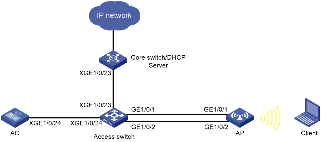
Network configuration
As shown in Figure 1, in centralized forwarding mode, the AC is connected to the access switch in hair-pin mode. The DHCP server assigns IP addresses to the AP and the client.
· Configure the client to come online in VLAN 200.
· Assign the AC to VLAN 100, and configure the AC and the AP to establish connections at Layer 2.
· Configure Layer 2 static link aggregation for the two uplink interfaces connecting the AP and the access switch. Configure load balancing based on source and destination MAC addresses for data traffic to be load balanced among different member ports of the aggregation.
You can configure the load balancing mode as needed. This example is for illustration only.
Analysis
· Enable the DHCP server feature on the core switch for the core switch to act as the DHCP server.
· Enable PoE on the access switch to supply power to the AP.
· Configure wireless services on the AC for the client to access the network wirelessly.
Restrictions and guidelines
· Use the actual serial ID of an AP to uniquely identify that AP.
· Forbids VLAN 1 traffic to be transmitted out of trunk ports to prevent packet accumulation in VLAN 1.
· As a best practice, use AP uplink interfaces that have the same port rate for link aggregation, and make sure the two peer interfaces on the switch also use the port rate. If the AP uplink interfaces use different port rates, only one interface can forward packets at a time, which increases link availability but disables load balancing.
Procedures
Configuring the core switch
1. Configure interfaces on the core switch:
# Create VLAN 100 and VLAN-interface 100, and assign an IP address to the VLAN interface. The AP will obtain an IP address from the address pool matching the interface address.
<Core switch> system-view
[Core switch] vlan 100
[Core switch-vlan100] quit
[Core switch] interface vlan-interface 100
[Core switch-Vlan-interface100] ip address 192.168.10.1 255.255.255.0
[Core switch-Vlan-interface100] quit
# Create VLAN 200 and VLAN-interface 200, and assign an IP address to the VLAN interface. The client will obtain an IP address from the address pool matching the interface address.
[Core switch] vlan 200
[Core switch-vlan200] quit
[Core switch] interface vlan-interface 200
[Core switch-Vlan-interface200] ip address 192.168.20.1 255.255.255.0
[Core switch-Vlan-interface200] quit
# Configure Ten-GigabitEthernet 1/0/23 that connects the core switch to the access switch as a trunk port, remove the port from VLAN 1, and assign the port to VLANs 100 and 200.
[Core switch] interface ten-gigabitethernet 1/0/23
[Core switch-Ten-GigabitEthernet1/0/23] port link-type trunk
[Core switch-Ten-GigabitEthernet1/0/23] undo port trunk permit vlan 1
[Core switch-Ten-GigabitEthernet1/0/23] port trunk permit vlan 100 200
[Core switch-Ten-GigabitEthernet1/0/23] quit
2. Configure the default route. (Details not shown.)
3. Configure the DHCP server:
# Enable the DHCP server feature.
[Core switch] dhcp enable
# Configure DHCP address pool 1, specify subnet 192.168.10.0/24, and set the gateway address as 192.168.10.1.
[Core switch] dhcp server ip-pool 1
[Core switch-dhcp-pool-1] network 192.168.10.0 mask 255.255.255.0
[Core switch-dhcp-pool-1] gateway-list 192.168.10.1
# Exclude 192.168.10.2 (IP address of VLAN-interface 100 of the AC) from IP allocation.
[Core switch-dhcp-pool-1] forbidden-ip 192.168.10.2
[Core switch-dhcp-pool-1] quit
# Configure DHCP address pool 2, specify subnet 192.168.20.0/24, set the gateway address, and specify the DNS server address. In this example, the DNS server address is also 192.168.20.1.
[Core switch] dhcp server ip-pool 2
[Core switch-dhcp-pool-2] network 192.168.20.0 mask 255.255.255.0
[Core switch-dhcp-pool-2] gateway-list 192.168.20.1
[Core switch-dhcp-pool-2] dns-list 192.168.20.1
[Core switch-dhcp-pool-2] quit
Configuring the AC
1. Edit the AP configuration file.
# Edit the AP configuration file, name the file map.txt, and upload the file to the AC.
system-view
interface Bridge-Aggregation1
quit
interface GigabitEthernet1/0/1
undo port-isolate enable
port link-aggregation group 1
quit
interface GigabitEthernet1/0/2
undo port-isolate enable
port link-aggregation group 1
quit
link-aggregation global load-sharing mode source-mac destination-mac
2. Configure the AC interfaces:
# Create VLAN 100, and assign an IP address to VLAN-interface 100. The AP will obtain an address in the same subnet as the interface address to establish CAPWAP tunnels with the AC.
[AC] vlan 100
[AC-vlan100] quit
[AC] interface vlan-interface 100
[AC-Vlan-interface100] ip address 192.168.10.2 255.255.255.0
[AC-Vlan-interface100] quit
# Create VLAN 200. The client will use this VLAN to access the WLAN.
[AC] vlan 200
[AC-vlan200] quit
# Configure Ten-GigabitEthernet 1/0/24 that connects the AC to the access switch as a trunk port, remove the port from VLAN 1, and assign the port to VLANs 100 and 200.
[AC] interface ten-gigabitethernet 1/0/24
[AC-Ten-GigabitEthernet1/0/24] port link-type trunk
[AC-Ten-GigabitEthernet1/0/24] undo port trunk permit vlan 1
[AC-Ten-GigabitEthernet1/0/24] port trunk permit vlan 100 200
[AC-Ten-GigabitEthernet1/0/24] quit
3. Configure wireless services:
# Create service template 1.
[AC] wlan service-template 1
# Specify the SSID as service.
[AC-wlan-st-1] ssid service
# Set the AKM mode to PSK, and specify the plaintext preshared key as 12345678.
[AC-wlan-st-1] akm mode psk
[AC-wlan-st-1] preshared-key pass-phrase simple 12345678
# Set the cipher suite to CCMP, and set the security IE to RSN.
[AC-wlan-st-1] cipher-suite ccmp
[AC-wlan-st-1] security-ie rsn
# Configure the AC to forward client data traffic. If the AC acts as the client traffic forwarder by default, skip this step.
[AC-wlan-st-1] client forwarding-location ac
# Enable the service template.
[AC-wlan-st-1] service-template enable
[AC-wlan-st-1] quit
4. Configure an AP:
|
|
NOTE: In a large-scale network, configure AP settings in AP group view instead of AP view as a best practice. |
# Create a manual AP named officeap, and specify the AP model and serial ID.
[AC] wlan ap officeap model WA6320
[AC-wlan-ap-officeap] serial-id 219801A28N819CE0002T
# Create AP group group1, and configure a grouping rule by AP name to add AP officeap to the group.
[AC] wlan ap-group group1
[AC-wlan-ap-group-group1] ap officeap
# Bind service template 1 to radio 1.
[AC-wlan-ap-group-group1] ap-model WA6320
[AC-wlan-ap-group-group1-ap-model-WA6320] radio 1
[AC-wlan-ap-group-group1-ap-model-WA6320-radio-1] service-template 1 vlan 200
# Enable radio 1.
[AC-wlan-ap-group-group1-ap-model-WA6320-radio-1] radio enable
[AC-wlan-ap-group-group1-ap-model-WA6320-radio-1] quit
# Deploy configuration file map.txt to APs in the AP group.
[AC-wlan-ap-group-group1-ap-model-WA6320] map-configuration map.txt
[AC-wlan-ap-group-group1-ap-model-WA6320] quit
[AC-wlan-ap-group-group1] quit
Configure the access switch
# Create VLANs 100 and 200. The switch will use VLAN 100 to forward the traffic on the CAPWAP tunnels between the AC and AP, and use VLAN 200 for client access.
<Access switch> system-view
[Access switch] vlan 100
[Access switch-vlan100] quit
[Access switch] vlan 200
[Access switch-vlan200] quit
# Configure Ten-GigabitEthernet 1/0/24 that connects the access switch to the AC as a trunk port, remove the port from VLAN 1, and assign the port to VLANs 100 and 200.
[Access switch] interface ten-gigabitEthernet 1/0/24
[Access switch-Ten-GigabitEthernet1/0/24] port link-type trunk
[Access switch-Ten-GigabitEthernet1/0/24] undo port trunk permit vlan 1
[Access switch-Ten-GigabitEthernet1/0/24] port trunk permit vlan 100 200
[Access switch-Ten-GigabitEthernet1/0/24] quit
# Configure Ten-GigabitEthernet 1/0/23 that connects the access switch to the core switch as a trunk port, remove the port from VLAN 1, and assign the port to VLANs 100 and 200.
[Access switch] interface ten-gigabitEthernet 1/0/23
[Access switch-Ten-GigabitEthernet1/0/23] port link-type trunk
[Access switch-Ten-GigabitEthernet1/0/23] undo port trunk permit vlan 1
[Access switch-Ten-GigabitEthernet1/0/23] port trunk permit vlan 100 200
[Access switch-Ten-GigabitEthernet1/0/23] quit
# Create Layer 2 aggregate interface 1, specify the interface as an access port, and assign the port to VLAN 100.
[Access switch] interface bridge-aggregation 1
[Access switch-Bridge-Aggregation1] port access vlan 100
[Access switch-Bridge-Aggregation1] quit
# Assign interfaces GigabitEthernet 1/0/1 and GigabitEthernet 1/0/2 to aggregation group 1, and enable PoE.
[Access switch] interface gigabitEthernet 1/0/1
[Access switch-GigabitEthernet1/0/1] port link-aggregation group 1
[Access switch-GigabitEthernet1/0/1] poe enable
[Access switch-GigabitEthernet1/0/1] quit
[Access switch] interface gigabitEthernet 1/0/2
[Access switch-GigabitEthernet1/0/2] port link-aggregation group 1
[Access switch-GigabitEthernet1/0/2] poe enable
[Access switch-GigabitEthernet1/0/2] quit
# Set the global load sharing mode to load share packets based on source and destination MAC addresses.
[Access switch] link-aggregation global load-sharing mode source-mac destination-mac
Verifying the configuration
1. View AP registration information on the AC:
# Verify that the AP has been associated with the AC. If the AP is in R/M state, the AP has been associated with the AC.
<AC> display wlan ap all
Total number of APs: 1
Total number of connected APs: 1
Total number of connected manual APs: 1
Total number of connected auto APs: 0
Total number of connected common APs: 1
Total number of connected WTUs: 0
Total number of inside APs: 0
Maximum supported APs: 20
Remaining APs: 19
Total AP licenses: 20
Local AP licenses: 20
Server AP licenses: 0
Remaining Local AP licenses: 19
Sync AP licenses: 0
AP information
State : I = Idle, J = Join, JA = JoinAck, IL = ImageLoad
C = Config, DC = DataCheck, R = Run, M = Master, B = Backup
AP name AP ID State Model Serial ID
officeap 1 R/M WA6320 219801A28N819CE0002T
2. View client information on the AC.
# Verify that the client has come online from radio 1 of the AP.
<AC> display wlan client
Total number of clients: 1
MAC address User name AP name R IP address VLAN
109a-dd9d-fc68 N/A officeap 1 192.168.20.4 200
3. View detailed information about the aggregation group on the access switch.
[Access switch] display link-aggregation verbose
Loadsharing Type: Shar -- Loadsharing, NonS -- Non-Loadsharing
Port Status: S -- Selected, U -- Unselected, I -- Individual
Flags: A -- LACP_Activity, B -- LACP_Timeout, C -- Aggregation,
D -- Synchronization, E -- Collecting, F -- Distributing,
G -- Defaulted, H -- Expired
Aggregate Interface: Bridge-Aggregation1
Aggregation Mode: Static
Loadsharing Type: Shar
Port Status Priority Oper-Key
--------------------------------------------------------------------------------
GE1/0/1 S 32768 1
GE1/0/2 S 32768 1
Configuration files
· Core switch:
#
dhcp enable
#
vlan 100
#
vlan 200
#
dhcp server ip-pool 1
gateway-list 192.168.10.1
network 192.168.10.0 mask 255.255.255.0
forbidden-ip 192.168.10.2
#
dhcp server ip-pool 2
gateway-list 192.168.20.1
network 192.168.20.0 mask 255.255.255.0
dns-list 192.168.20.1
#
interface Vlan-interface100
ip address 192.168.10.1 255.255.255.0
#
interface Vlan-interface200
ip address 192.168.20.1 255.255.255.0
#
interface Ten-GigabitEthernet1/0/23
port link-type trunk
undo port trunk permit vlan 1
port trunk permit vlan 100 200
#
· AC:
#
vlan 100
#
vlan 200
#
wlan service-template 1
ssid service
client forwarding-location ac
akm mode psk
preshared-key pass-phrase cipher $c$3$N//5BVbsOqdBTxi+7MJZKT6Zqh5MAmYs2ZzM
cipher-suite ccmp
security-ie rsn
service-template enable
#
interface Vlan-interface100
ip address 192.168.10.2 255.255.255.0
#
interface Ten-GigabitEthernet1/0/24
port link-type trunk
undo port trunk permit vlan 1
port trunk permit vlan 100 200
#
wlan ap-group group1
ap officeap
ap-model WA6320
map-configuration map.txt
radio 1
service-template 1 vlan 200
radio enable
#
wlan ap officeap model WA6320
serial-id 219801A28N819CE0002T
#
· Access switch:
#
link-aggregation global load-sharing mode destination-mac source-mac
#
vlan 100
#
vlan 200
#
interface GigabitEthernet1/0/1
port link-aggregation group 1
poe enable
#
interface GigabitEthernet1/0/2
port link-aggregation group 1
poe enable
#
interface Ten-GigabitEthernet1/0/23
port link-type trunk
undo port trunk permit vlan 1
port trunk permit vlan 100 200
#
interface Ten-GigabitEthernet1/0/24
port link-type trunk
undo port trunk permit vlan 1
port trunk permit vlan 100 200
#
interface bridge-aggregation 1
port access vlan 100
Related documentation
· AP Management Command Reference in H3C Access Controllers Command References
· AP Management Configuration Guide in H3C Access Controllers Configuration Guides
· Ethernet Link Aggregation Command Reference in H3C Access Controllers Command References
· Ethernet Link Aggregation Configuration Guide in H3C Access Controllers Configuration Guides
· Network Connectivity Command Reference in H3C Access Controllers Command References
· Network Connectivity Configuration Guide in H3C Access Controllers Configuration Guides
· Port Isolation Command Reference in H3C Access Controllers Command References
· Port Isolation Configuration Guide in H3C Access Controllers Configuration Guides
· WLAN Access Configuration Guide in H3C Access Controllers Configuration Guides
· WLAN Access Command Reference in H3C Access Controllers Command References
