- Table of Contents
-
- 05-Comware 9 CLI-based configuration examples (AC+fit AP deployment)
- 01-HTTPS Login Configuration Examples
- 02-SSH Configuration Examples
- 03-License Management Configuration Examples
- 04-AP Association with the AC at Layer 2 Configuration Examples
- 05-AP Association with the AC at Layer 2 (IPv6) Configuration Examples
- 06-Auto AP Configuration Examples
- 07-AP Association with the AC at Layer 3 Configuration Examples
- 08-AP Association with the AC at Layer 3 (IPv6) Configuration Examples
- 09-WEP Encryption Configuration Examples
- 10-PSK Encryption Configuration Examples
- 11-WPA3-SAE PSK Encryption Configuration Examples
- 12-WLAN Access (IPv6) Configuration Examples
- 13-Policy-Based Forwarding with Dual Gateways Configuration Examples
- 14-Scheduled Configuration Deployment by AP Group Configuration Examples
- 15-Inter-AC Roaming with Static Client VLAN Allocation Configuration Examples
- 16-Service Template and Radio Binding Configuration Examples
- 17-Scheduled WLAN Access Services Configuration Examples
- 18-Local Portal Authentication Configuration Examples
- 19-HTTPS-Based Local Portal Authentication Configuration Examples
- 20-Remote Portal Authentication Configuration Examples
- 21-Local Portal Authentication through LDAP Server Configuration Examples
- 22-Local Portal Auth and SSID-based Auth Page Pushing Configuration Examples
- 23-Local Portal MAC-Trigger Authentication Configuration Examples
- 24-Portal MAC-Trigger Authentication Configuration Examples
- 25-Local Forwarding Mode and Local Portal MAC-Trigger Auth Configuration Examples
- 26-Local Portal Authentication (IPv6) Configuration Examples
- 27-Local Portal Authentication through LDAP Server (IPv6) Configuration Examples
- 28-Remote Portal Authentication (IPv6) Configuration Examples
- 29-Portal MAC-Trigger Authentication (IPv6) Configuration Example
- 30-Remote Portal Authentication with User Profile Authorization Configuration Examples
- 31-Portal Fail-Permit Configuration Examples
- 32-Local MAC Authentication Configuration Examples
- 33-Remote MAC Authentication Configuration Examples
- 34-Transparent Auth Through Remote MAC and Portal Auth Configuration Examples
- 35-Remote AP, Remote Portal, and MAC-Trigger Authentication Configuration Examples
- 36-MAC Authentication with Guest VLAN Assignment Configuration Examples
- 37-MAC Authentication with Guest VLAN Assignment (IPv6) Configuration Examples
- 38-Local MAC-And-802.1X Authentication Configuration Examples
- 39-Local 802.1X Authentication Configuration Examples
- 40-Local RADIUS-Based 802.1X Authentication in EAP Relay Mode Configuration Examples
- 41-Remote 802.1X Authentication Configuration Examples
- 42-Remote 802.1X Authentication (IPv6) Configuration Examples
- 43-Remote 802.1X Authentication in WPA3-Enterprise Mode Configuration Examples
- 44-802.1X Auth with ACL Assignment Through IMC Server Configuration Examples
- 45-802.1X Auth with User Profile Assignment Through IMC Server Configuration Examples
- 46-EAD Authentication Configuration Examples
- 47-EAD Authentication (IPv6) Configuration Examples
- 48-Local Forwarding Mode and Local Portal Authentication Configuration Examples
- 49-Local Forwarding Mode Direct Portal Authentication Configuration Examples
- 50-Local Forwarding Mode Direct Portal Authentication (IPv6) Configuration Examples
- 51-Local Forwarding Configuration Examples
- 52-Wired Port Local Forwarding through Wireless Terminator Configuration Examples
- 53-Remote AP Configuration Examples
- 54-Downlink VLAN Management for Fit-Mode APs Configuration Examples
- 55-WIPS Configuration Examples
- 56-WIPS Countermeasures Against All SSIDs Configuration Examples
- 57-IP Source Guard (IPv4) Configuration Examples
- 58-IP Source Guard (IPv6) Configuration Examples
- 59-Dual-Link Backup Configuration Examples
- 60-OAuth-Based Portal MAC-Trigger Auth on a Local-Forwarding Dual-Link Backup Configuration Examples
- 61-Dual-Link Backup OAuth-Based Portal Authentication in Local Forwarding Configuration Examples
- 62-Dual-Link Backup Remote Portal MAC-Trigger Authentication in Local Forwarding Configuration Examples
- 63-Dual-Link Backup Remote Portal and Transparent MAC Auth in Local Forwarding Configuration Examples
- 64-Dual-Link Backup Remote Portal Authentication in Local Forwarding Configuration Examples
- 65-Dual-Link Backup Remote Portal and Transparent MAC Auth in Centralized Forwarding Configuration Examples
- 66-Dual-Link Backup Remote Portal Authentication in Centralized Forwarding Configuration Examples
- 67-Dual-Link Backup Lightweight Portal Authentication in Centralized Forwarding Configuration Examples
- 68-Dual-Link Backup OAuth-Based Portal Authentication in Centralized Forwarding Configuration Examples
- 69-Dual-Link Backup Remote Portal MAC-Trigger Auth in Centralized Forwarding Configuration Examples
- 70-Remote 802.1X Authentication on a Dual-Link AC Backup Network Configuration Examples
- 71-Remote MAC Authentication on a Dual-Link AC Backup Network Configuration Examples
- 72-WLAN Probe Configuration Examples
- 73-Multicast Optimization Configuration Examples
- 74-Client Rate Limiting Configuration Examples
- 75-Inter-AC Roaming Configuration Examples
- 76-Inter-AC Roaming (IPv6) Configuration Examples
- 77-Inter-AC Roaming in Local Forwarding Mode Configuration Examples
- 78-H3C Access Controllers Cooperative Roaming for 802.11v Clients Configuration Examples
- 79-WLAN Load Balancing Configuration Examples
- 80-Static Blacklist Configuration Examples
- 81-Client Quantity Control Configuration Examples
- 82-AP License Synchronization Configuration Examples
- 83-BLE Module iBeacon Transmission Configuration Examples
- 84-Medical RFID Tag Management Configuration Examples
- 85-iBeacon Management Configuration Examples
- 86-Mesh Link Establishment Between a Fit AP and a Fat AP Configuration Examples
- 87-Mesh Link Establishment Between Fit APs Configuration Examples
- 88-Auto-DFS and Auto-TPC Configuration Examples
- 89-AP Image Downloading Configuration Examples
- 90-Dual-Uplink Interfaces Configuration Guide
- 91-Internal-to-External Access Through NAT Configuration Examples
- 92-Layer 2 Static Aggregation Configuration Examples
- 93-Layer 2 Multicast Configuration Examples
- 94-Static VLAN Allocation Configuration Examples
- 95-URL Redirection Configuration Examples
- 96-IPv6 URL Redirection Configuration Examples
- Related Documents
-
| Title | Size | Download |
|---|---|---|
| 29-Portal MAC-Trigger Authentication (IPv6) Configuration Example | 829.64 KB |
|
|
|
H3C Access Controllers |
|
IPv6 Portal MAC-Trigger Authentication |
|
Configuration Examples |
Copyright © 2023 New H3C Technologies Co., Ltd. All rights reserved.
No part of this manual may be reproduced or transmitted in any form or by any means without prior written consent of New H3C Technologies Co., Ltd.
Except for the trademarks of New H3C Technologies Co., Ltd., any trademarks that may be mentioned in this document are the property of their respective owners.
The information in this document is subject to change without notice.
Contents
Example: Configuring IPv6 portal MAC-trigger authentication
Editing a configuration file for the AP
Introduction
The following information provides examples for configuring IPv6 portal MAC-trigger authentication (also called MAC-based quick portal authentication or transparent portal authentication).
Prerequisites
The following information applies to Comware-based access controllers and access points. Procedures and information in the examples might be slightly different depending on the software or hardware version of the access controllers and access points.
The configuration examples were created and verified in a lab environment, and all the devices were started with the factory default configuration. When you are working on a live network, make sure you understand the potential impact of every command on your network.
The following information is provided based on the assumption that you have basic knowledge of AAA, portal, and WLAN.
Example: Configuring IPv6 portal MAC-trigger authentication
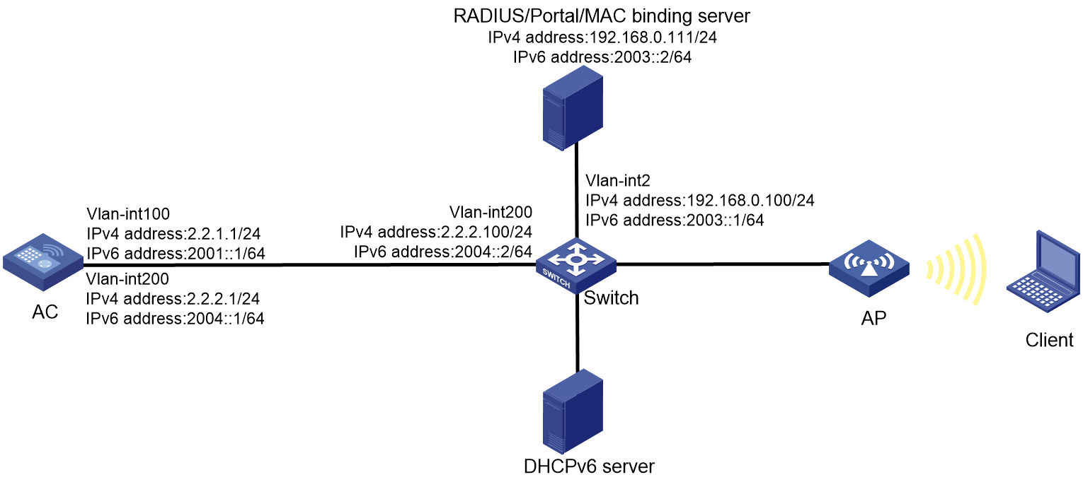
Network configuration
As shown in Figure 1, the AP and the client obtain IP addresses and IPv6 addresses from the DHCP server and the DHCPv6 server, respectively. The IMC server acts a portal authentication server, a portal Web server, a MAC binding server, and a RADIUS server.
Configure direct portal authentication and MAC-trigger authentication to meet the following requirements:
· The client can access only the portal Web servers before passing portal authentication and can access other network resources after passing portal authentication.
· The client can access the network resources through any Layer 2 ports in its access VLAN without re-authentication.
· The RADIUS server can dynamically change the user authorization information or forcibly disconnect users.
Analysis
To implement IPv6 portal MAC-trigger authentication, assign both IPv4 and IPv6 addresses to the AC, the client, and the IMC server. Make sure both IPv4 and IPv6 routes between them are reachable.
For the client to access network resources through any Layer 2 ports in its access VLAN without re-authentication, enable portal roaming.
For the RADIUS server to dynamically change the user authorization information or forcibly disconnect users, enable the RADIUS session-control feature.
To use GigabitEthernet 1/0/1 on the AP to forward client traffic, edit a .txt configuration file and upload the file to the AC.
To ensure that dynamic user authorization information can be correctly assigned to users after they come online, enable the RADIUS DAS feature.
To allow portal users to access both IPv4 and IPv6 networks after passing one type (IPv4 or IPv6) of portal authentication, enable portal to support IPv4/IPv6 dual stack.
To view the IPv6 address of the client on the AC, enable ND snooping and DHCPv6 snooping.
Configure DNS if necessary. In this example, DNS is not required.
Restrictions and guidelines
When you configure IPv6 portal MAC-trigger authentication, follow these restrictions and guidelines:
· Use the serial ID labeled on the AP's rear panel to specify an AP.
· Make sure the types of the portal authentication servers, portal Web servers, and MAC binding server specified on the AC are the same as those actually used.
· By default, the URL of the portal Web server to which the AC redirects portal users does not carry any parameters. You can add parameters to be carried in the URL as needed.
· If portal authentication is enabled on a VLAN interface, only the AC can forward client traffic. If portal authentication is enabled on a service template, both the AC and the AP can forward client traffic. (In this example, portal authentication is enabled on a service template.)
· If you have set the free-traffic threshold, portal clients cannot automatically push portal authentication pages and portal users need to manually open a browser to open the pages. Do not set the free-traffic threshold if you want portal clients to automatically push portal authentication pages.
· Some types of endpoints use random MAC by default, which might cause failure of the MAC-trigger authentication. As a best practice, disable the random MAC feature on the endpoints.
Procedures
Configuring IMC
This example uses the IMC server to describe the RADIUS server, portal server, and MAC binding server configuration. The IMC server runs on IMC PLAT 7.1 (E0303), IMC EIA 7.1 (E0304), and IMC EIP 7.1 (E0304).
Configuring the RADIUS server
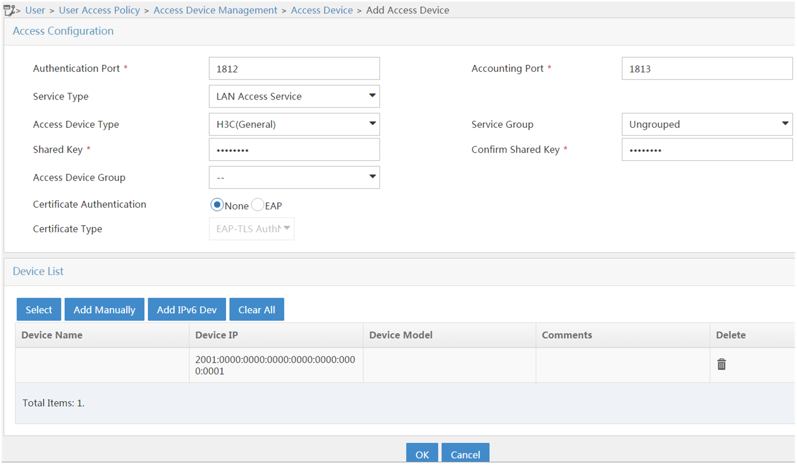
Add the AC to IMC as an IPv4 access device and an IPv6 access device:
1. Log in to IMC and click the User tab.
2. From the navigation tree, select User Access Policy > Access Device Management > Access Device.
3. Click Add to open the page as shown in Figure 2.
4. In the Access Configuration area, set the shared key to radius, which must be the same as that on the AC.
5. In the Device List area, perform the following operations:
a. Click Add Manually to open the Add Access Device Manually page. Enter the start IPv4 address 2.2.2.1 and then click OK.
b. Click Add IPv6 Dev to open the Add Access Device Manually page. Enter the start IPv6 address 2001::1 and then click OK.
6. Use the default values for other parameters.
7. Click OK.
Figure 2 Adding the AC as an IPv4 access device
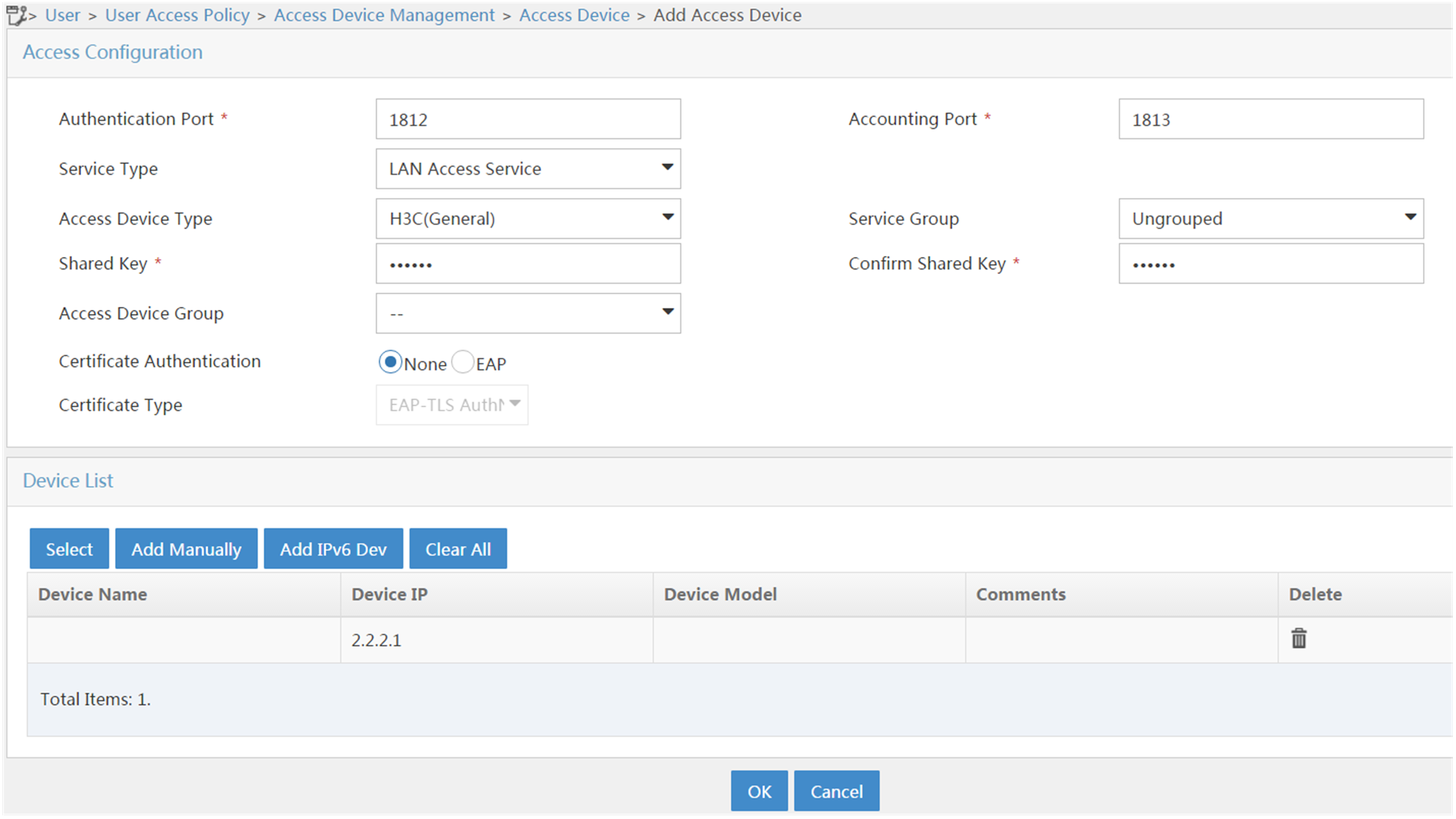
Figure 3 Adding the AC as an IPv6 access device
Configuring the portal server
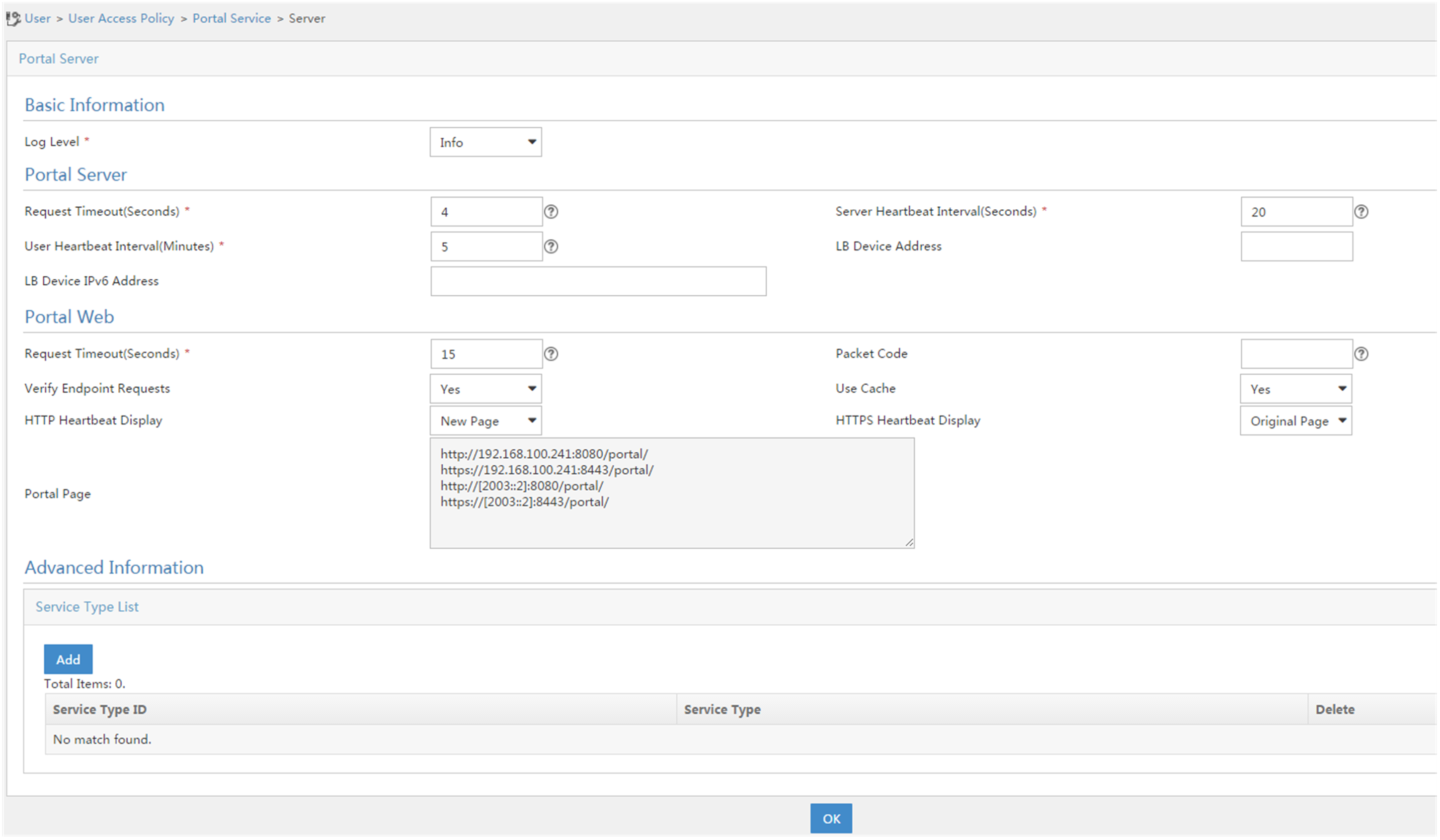
1. Configure the portal authentication service:
a. Click the User tab.
b. From the navigation tree, select User Access Policy > Portal Service > Server to open the portal server configuration page, as shown in Figure 4.
c. Configure the portal server parameters as needed.
This example uses the default values.
d. Click OK.
Figure 4 Portal authentication server configuration
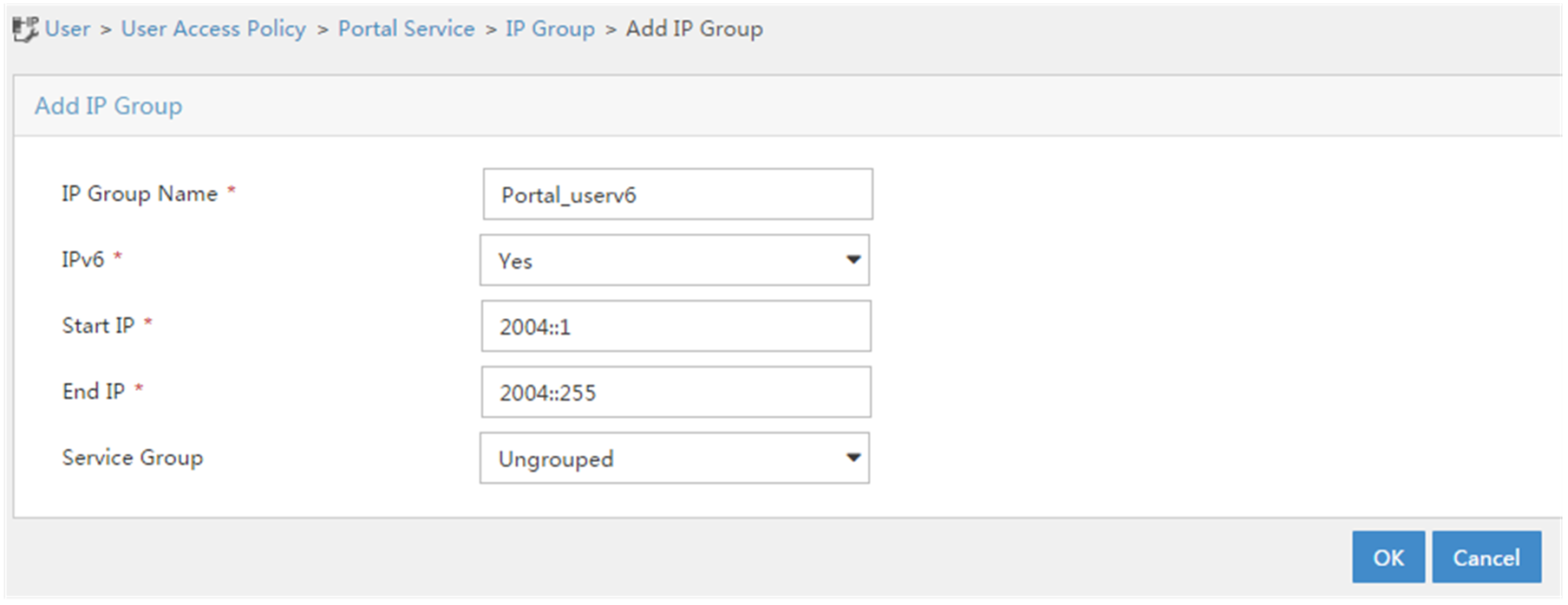
2. Configure an IPv4 group and an IPv6 group:
a. From the navigation tree, select User Access Policy > Portal Service > IP Group.
b. Click Add.
The Add IP Group page opens.
c. Enter an IP group name.
d. To add an IPv4 group, select No from the IPv6 field.
e. To add an IPv6 group, select Yes from the IPv6 field.
f. Enter the start IP address and end IP address of the IP group.
Make sure the client IP address is in the IP group.
g. Select a service group.
This example uses the default value Ungrouped.
h. Select Normal from the Action field.
This step is required only when you add an IPv4 address group.
i. Click OK.
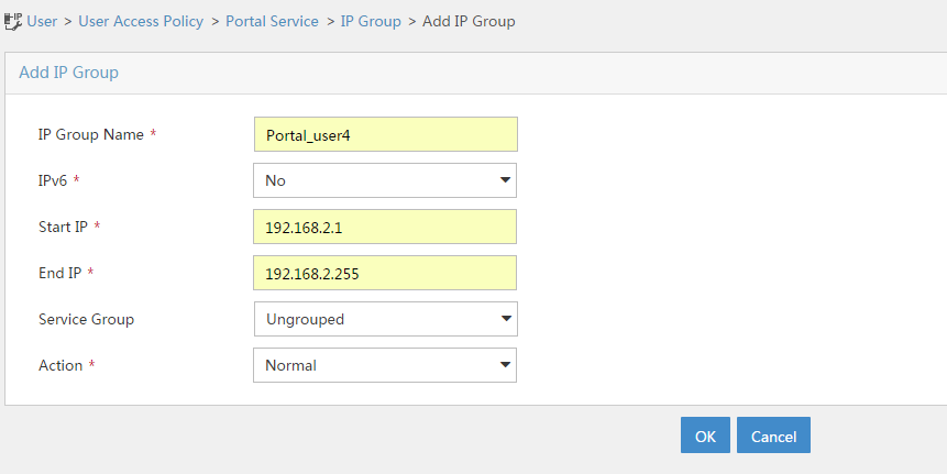
Figure 6 Adding an IPv6 group
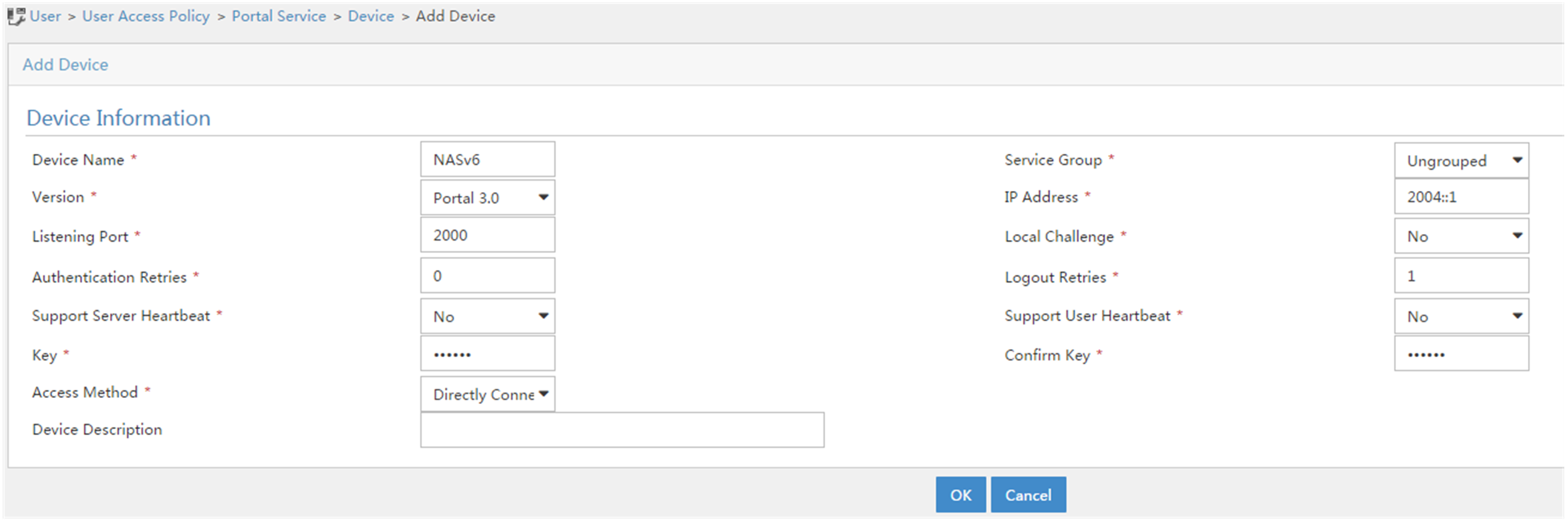
3. Add the portal device:
a. From the navigation tree, select User Access Policy > Portal Service > Device.
b. Click Add.
The Add Device page opens.
c. Enter the device name.
d. Select a portal version.
For an IPv4 portal device, select Portal 2.0. For an IPv6 portal device, select Portal 3.0.
e. Enter the IP address of the AC's interface connected to the client.
f. Set whether to support the portal server heartbeat and user heartbeat functions.
In this example, select No for both Support Server Heartbeat and Support User Heartbeat.
g. Enter the key, which must be the same as that configured on the AC.
h. Select Directly Connected for Access Method.
i. Use the default settings for other parameters.
j. Click OK.
Figure 7 Adding an IPv4 portal device
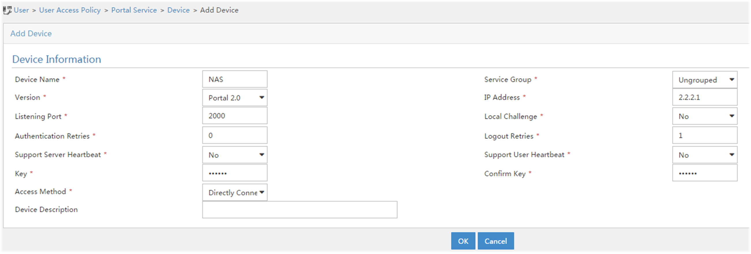
Figure 8 Adding an IPv6 portal device
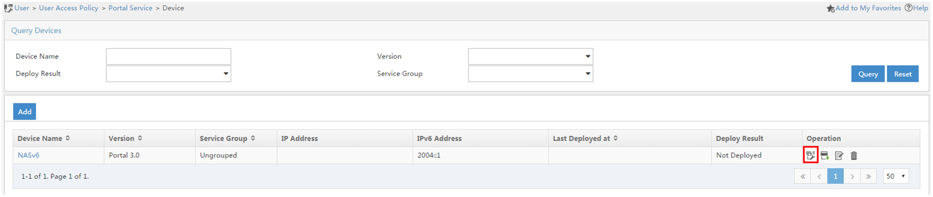
4. Associate a portal device with an IP group:
a. In the device list page, click the Port Group icon ![]() in the Operation field for a portal device
to open the port group configuration page.
in the Operation field for a portal device
to open the port group configuration page.
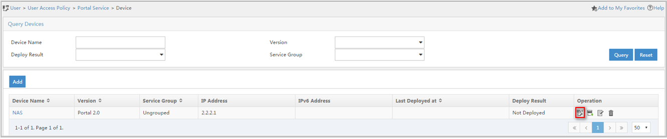
Figure 10 IPv6 device list
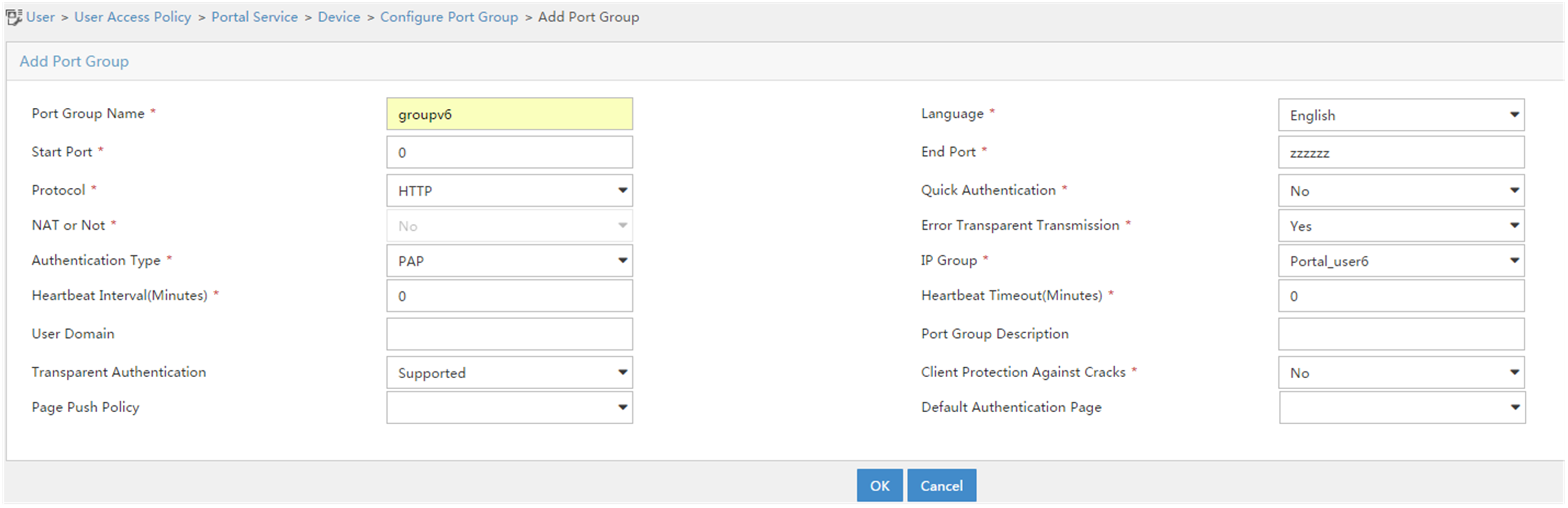
b. Click Add to open the Add Port Group page.
- Enter the port group name.
- Select the configured IP group.
- The IP address used by the user to access the network must be within this IP group.
- Select Supported for Transparent Authentication.
- Use the default settings for other parameters.
c. Click OK.
Figure 11 Adding an IPv4 port group
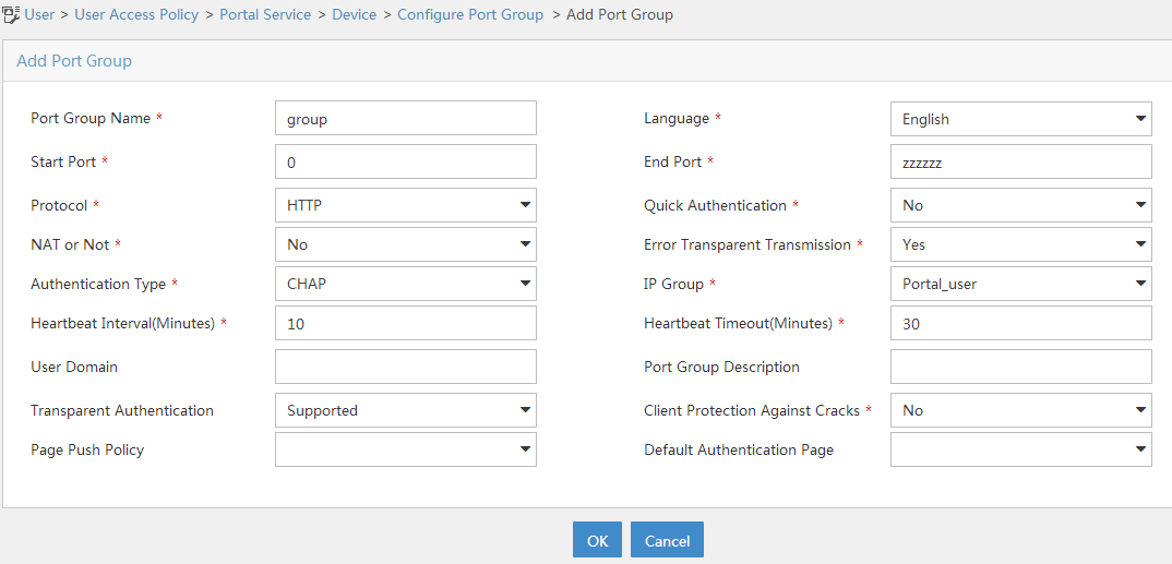
Figure 12 Adding an IPv6 port group
5. From the navigation tree, select User Access Policy > Service Parameters > Validate System Configuration to commit the configuration changes.
Configuring the MAC binding server
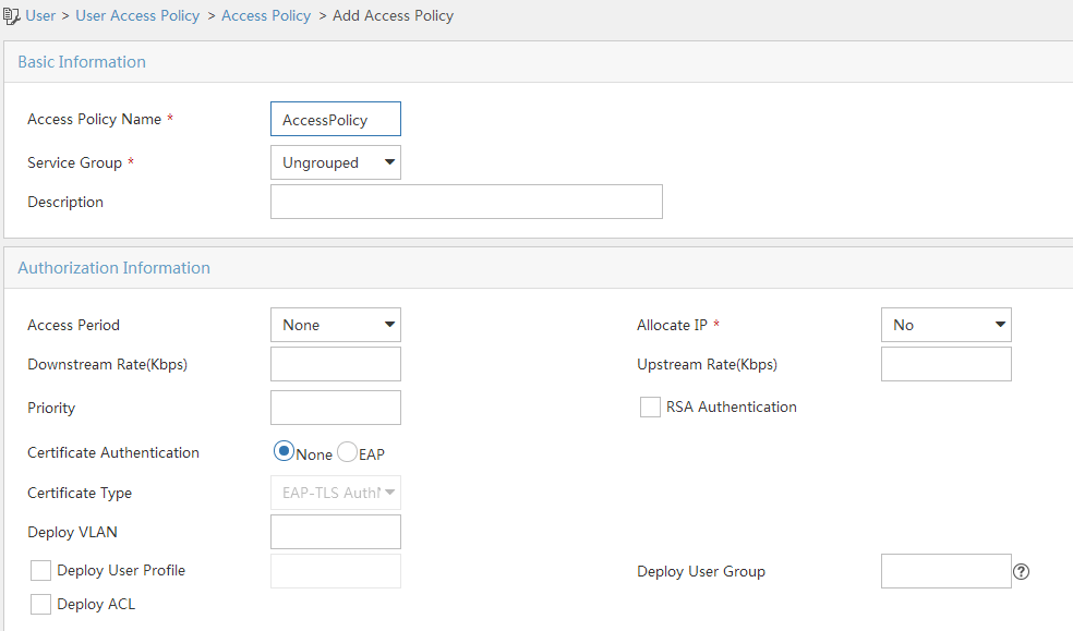
1. Add an access policy:
a. From the navigation tree, select User Access Policy > Access Policy.
b. Click Add to open the page as shown in Figure 13.
c. Enter the access policy name.
d. Select a service group.
This example uses the default value Ungrouped.
e. Use the default settings for other parameters.
f. Click OK.
Figure 13 Adding an access policy
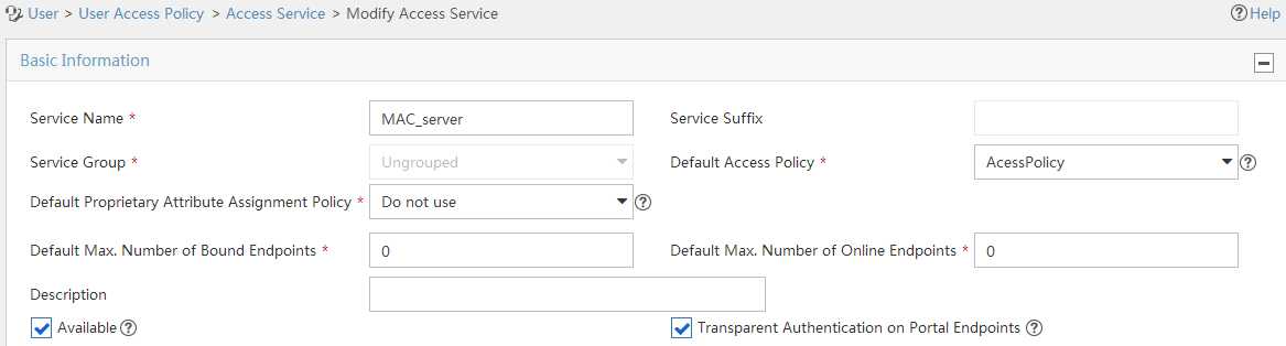
2. Add an access service:
a. From the navigation tree, select User Access Policy > Access Service.
b. Click Add to open the page as shown in Figure 14.
c. Enter the service name.
d. Select a default access policy.
e. Select the Transparent Authentication on Portal Endpoints option.
f. Use the default settings for other parameters.
g. Click OK.
Figure 14 Adding an access service
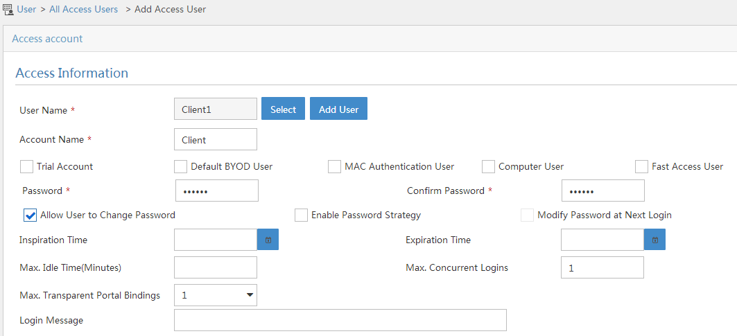
3. Add an access user:
a. From the navigation tree, select Access User > All Access Users.
b. Click Add to open the page as shown in Figure 15.
c. Click Select to select an existing access user or click Add User to add a new access user.
d. Enter the account name.
e. Set the password.
f. Select a value from the Max. Transparent Portal Bindings list.
g. Use the default settings for other parameters.
h. Click OK.
Figure 15 Adding an access user
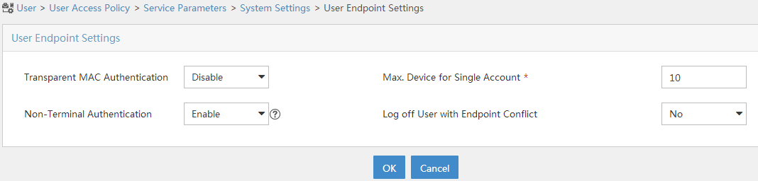
4. Configure system parameters:
a. From the navigation tree, select User Access Policy > Service Parameters > System Settings.
b. Click the Configure
icon ![]() for User Endpoint Settings to open the
page as shown in Figure 16.
for User Endpoint Settings to open the
page as shown in Figure 16.
c. Select whether to enable transparent portal authentication on non-smart devices.
In this example, select Enable for Non-Terminal Authentication.
d. Click OK.
Figure 16 Configuring user endpoint settings
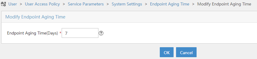
e. Click the Configure
icon ![]() for Endpoint Aging Time to open the page
as shown in Figure 17.
for Endpoint Aging Time to open the page
as shown in Figure 17.
f. Set the endpoint aging time as needed.
This example uses the default value.
g. Click OK.
Figure 17 Setting the endpoint aging time
5. From the navigation tree, select User Access Policy > Service Parameters > Validate System Configuration to commit the configuration changes.
Editing a configuration file for the AP
# Create a .txt configuration file named map.txt.
# Enter the following content in the file.
System-view
vlan 200
interface gigabitethernet1/0/1
port trunk permit vlan 200
# Upload the file to the AC.
Configuring the AC
1. Configure interfaces on the AC:
# Create VLAN 100 and VLAN-interface 100, and assign an IPv4 address and an IPv6 address to the VLAN interface. The AC will establish a CAPWAP tunnel with the AP in this VLAN.
<AC> system-view
[AC] vlan 100
[AC-vlan100] quit
[AC] interface vlan-interface 100
[AC-Vlan-interface100] ip address 2.2.1.1 24
[AC-Vlan-interface100] ipv6 address 2001::1 64
# Configure VLAN-interface 100 not to suppress RA message advertisement.
[AC-Vlan-interface100] undo ipv6 nd ra halt
# Set the managed address configuration flag (M) to 1 in RA advertisements to be sent on VLAN-interface 100.
[AC-Vlan-interface100] ipv6 nd autoconfig managed-address-flag
# Set the O flag to 1 in RA advertisements to be sent on VLAN-interface 100.
[AC-Vlan-interface100] ipv6 nd autoconfig other-flag
[AC-Vlan-interface100] quit
# Create VLAN 200 and VLAN-interface 200, and assign an IPv4 address and an IPv6 address to the VLAN interface. The AC will use VLAN 200 for client access.
[AC] vlan 200
[AC-vlan200] quit
[AC] interface vlan-interface 200
[AC-Vlan-interface200] ip address 2.2.2.1 24
[AC-Vlan-interface200] ipv6 address 2004::1 64
# Configure VLAN-interface 200 not to suppress RA message advertisement.
[AC-Vlan-interface200] undo ipv6 nd ra halt
# Set the managed address configuration flag (M) to 1 in RA advertisements to be sent on VLAN-interface 200.
[AC-Vlan-interface200] ipv6 nd autoconfig managed-address-flag
# Set the O flag to 1 in RA advertisements to be sent on VLAN-interface 200.
[AC-Vlan-interface200] ipv6 nd autoconfig other-flag
[AC-Vlan-interface200] quit
# Configure GigabitEthernet 1/0/1 (the interface connected to the switch) as a trunk port and assign it to VLAN 100 and VLAN 200.
[AC] interface gigabitethernet 1/0/1
[AC-GigabitEthernet1/0/1] port link-type trunk
[AC-GigabitEthernet1/0/1] port trunk permit vlan 100 200
[AC-GigabitEthernet1/0/1] quit
2. Configure a static IPv4 route and a static IPv6 route to the IMC server.
[AC] ip route-static 192.168.0.0 255.255.0.0 2.2.2.100
[AC] ipv6 route-static 2003:: 64 2004::2
3. Configure a WLAN service:
# Create a service template named st1 and enter its view.
[AC] wlan service-template st1
# Set the SSID of service template st1 to service.
[AC-wlan-st-st1] ssid service
# Assign clients coming online through service template st1 to VLAN 200.
[AC-wlan-st-st1] vlan 200
# Configure APs to forward client data traffic from all VLANs.
[AC–wlan-st-st1] client forwarding-location ap
[AC-wlan-st-st1] quit
4. Configure the AP:
|
|
NOTE: In large-scale networks, configure AP groups instead of single APs as a best practice. |
# Create an AP named ap1 with model WA6320 and set its serial ID to 219801A28N819CE0002T.
[AC] wlan ap ap1 model WA6320
[AC-wlan-ap-ap1] serial-id 219801A28N819CE0002T
# Create an AP group named group1 and add AP ap1 to the AP group.
[AC] wlan ap-group group1
[AC-wlan-ap-group-group1] ap ap1
# Create an AP model named WA6320 in AP group group1 and then deploy configuration file map.txt to the AP.
[AC-wlan-ap-group-group1] ap-model WA6320
[AC-wlan-ap-group-group1-ap-model-WA6320] map-configuration map.txt
# Enter the AP group's radio 2 view, and bind service template st1 to radio 2.
[AC-wlan-ap-group-group1-ap-model-WA6320] radio 2
[AC-wlan-ap-group-group1-ap-model-WA6320-radio-2] service-template st1
# Enable radio 2.
[AC-wlan-ap-group-group1-ap-model-WA6320-radio-2] radio enable
[AC-wlan-ap-group-group1-ap-model-WA6320-radio-2] return
5. Configure an IPv4 RADIUS scheme:
# Create a RADIUS scheme named rs1 and enter its view.
<AC> system-view
[AC] radius scheme rs1
# Specify the primary authentication server and primary accounting server, and configure the keys for communication with the servers.
[AC-radius-rs1] primary authentication 192.168.0.111
[AC-radius-rs1] primary accounting 192.168.0.111
[AC-radius-rs1] key authentication simple radius
[AC-radius-rs1] key accounting simple radius
# Configure the AC to remove the domain name from the usernames sent to the RADIUS servers.
[AC-radius-rs1] user-name-format without-domain
# Specify IP address 2.2.2.1 as the source IP address for outgoing RADIUS packets.
[AC-radius-rs1] nas-ip 2.2.2.1
[AC-radius-rs1] quit
# Enable RADIUS session-control.
[AC] radius session-control enable
# Enable the RADIUS DAS feature and enter RADIUS DAS view.
[AC] radius dynamic-author server
# Specify a session-control client with IP address 192.168.0.111 and shared key radius in plaintext form.
[AC-radius-da-server] client ip 192.168.0.111 key simple radius
[AC-radius-da-server] quit
6. Configure an IPv6 RADIUS scheme:
# Create a RADIUS scheme named rs2 and enter its view.
[AC] radius scheme rs2
# Specify the primary authentication server and primary accounting server, and configure the keys for communication with the servers.
[AC-radius-rs2] primary authentication ipv6 2003::2
[AC-radius-rs2] primary accounting ipv6 2003::2
[AC-radius-rs2] key authentication simple radius
[AC-radius-rs2] key accounting simple radius
# Configure the AC to remove the domain name from the usernames sent to the RADIUS servers.
[AC-radius-rs2] user-name-format without-domain
# Specify IPv6 address 2004::1 as the source IPv6 address for outgoing RADIUS packets.
[AC-radius-rs1] nas-ip ipv6 2004::1
[AC-radius-rs2] quit
# Enter RADIUS DAS view.
[AC] radius dynamic-author server
# Specify a session-control client with IPv6 address 2003::2 and shared key radius in plaintext form.
[AC-radius-da-server] client ipv6 2003::2 key simple radius
[AC-radius-da-server] quit
7. Configure an IPv4 authentication domain:
# Create an ISP domain named dm1 and enter its view.
[AC] domain dm1
# Configure the authentication and authorization methods as RADIUS and the accounting method as none in the ISP domain.
[AC-isp-dm1] authentication portal radius-scheme rs1
[AC-isp-dm1] authorization portal radius-scheme rs1
[AC-isp-dm1] accounting portal none
# Configure the idle cut feature for users in the ISP domain. Log out a user if the user's traffic is less than 1024 bytes in 15 minutes.
[AC-isp-dm1] authorization-attribute idle-cut 15 1024
[AC-isp-dm1] quit
8. Configure an IPv6 authentication domain:
# Create an ISP domain named dm2 and enter its view.
[AC] domain dm2
# Configure the authentication and authorization methods as RADIUS and the accounting method as none in the ISP domain.
[AC-isp-dm2] authentication portal radius-scheme rs2
[AC-isp-dm2] authorization portal radius-scheme rs2
[AC-isp-dm2] accounting portal none
# Configure the idle cut feature for users in the ISP domain. Log out a user if the user's traffic is less than 1024 bytes in 15 minutes.
[AC-isp-dm2] authorization-attribute idle-cut 15 1024
[AC-isp-dm2] quit
9. Configure portal authentication:
# Create an IPv4 portal authentication server named newptv4, and specify IPv4 address 192.168.0.111 for the authentication server.
[AC] portal server newptv4
[AC-portal-server-newptv4] ip 192.168.0.111 key simple 123456
[AC-portal-server-newptv4] quit
# Create an IPv6 portal authentication server named newptv6, and specify IPv6 address 2003::2 for the authentication server.
[AC] portal server newptv6
[AC-portal-server-newptv6] ipv6 2003::2 key simple 123456
[AC-portal-server-newptv6] quit
# Specify http://192.168.0.111:8080/portal as the URL of IPv4 portal Web server newptv4.
[AC] portal web-server newptv4
[AC-portal-websvr-newptv4] url http://192.168.0.111:8080/portal
# Configure the portal redirection URL to carry the ssid, wlanuserip, and wlanacname parameters, and their values are the AP's SSID, the user's IP address, and the AC's name.
[AC-portal-websvr-newptv4] url-parameter ssid ssid
[AC-portal-websvr-newptv4] url-parameter wlanuserip source-address
[AC-portal-websvr-newptv4] url-parameter wlanacname value AC
[AC-portal-websvr-newptv4] quit
# Specify http://[2003::2]:8080/portal as the URL of IPv6 portal Web server newptv6.
[AC] portal web-server newptv6
[AC-portal-websvr-newptv6] url http://[2003::2]:8080/portal
# Configure the portal redirection URL to carry the ssid, wlanuserip, and wlanacname parameters, and their values are the AP's SSID, the user's IP address, and the AC's name.
[AC-portal-websvr-newptv6] url-parameter ssid ssid
[AC-portal-websvr-newptv6] url-parameter wlanuserip source-address
[AC-portal-websvr-newptv6] url-parameter wlanacname value AC
[AC-portal-websvr-newptv6] quit
# Enable portal roaming.
[AC] portal roaming enable
# Enable validity check on wireless portal clients.
[AC] portal host-check enable
# Enable direct IPv4 portal authentication and direct IPv6 portal authentication on service template st1.
[AC] wlan service-template st1
[AC-wlan-st-st1] portal enable method direct
[AC-wlan-st-st1] portal ipv6 enable method direct
# Enable snooping ND packets and snooping DHCPv6 packets on service template st1.
[AC-wlan-st-st1] client ipv6-snooping nd-learning enable
[AC-wlan-st-st1] client ipv6-snooping dhcpv6-learning enable
# Specify ISP domain dm1 as the portal authentication domain for IPv4 portal users.
[AC-wlan-st-st1] portal domain dm1
# Specify ISP domain dm2 as the portal authentication domain for IPv6 portal users.
[AC-wlan-st-st1] portal domain dm2
# Specify IPv4 portal Web server newptv4 and IPv6 portal Web server newptv6 on service template st1 for portal authentication.
[AC-wlan-st-st1] portal apply web-server newptv4
[AC-wlan-st-st1] portal ipv6 apply web-server newptv6
# Enable portal to support IPv4/IPv6 dual stack on service template st1.
[AC-wlan-st-st1] portal dual-stack enable
# Configure the BAS-IP attribute as 2.2.2.1 and the BAS-IPv6 attribute as 2004::1.
[AC-wlan-st-st1] portal bas-ip 2.2.2.1
[AC-wlan-st-st1] portal bas-ipv6 2004::1
[AC-wlan-st-st1] quit
# Configure two destination-based portal-free rules to permit the traffic destined for the DNS server.
[AC] portal free-rule 1 destination ip any udp 53
[AC] portal free-rule 2 destination ip any tcp 53
# Configure a source-based portal-free rule. Set the rule number to 3 and the source interface to aggregate interface 1. This rule allows the portal user on the aggregate interface to access network resources without authentication.
[AC] portal free-rule 3 source interface Bridge-Aggregation1
10. Configure MAC-based quick portal authentication:
# Create a MAC binding server named mts and enter its view.
[AC] portal mac-trigger-server mts
# Specify 192.168.0.111 as the IPv4 address of MAC binding server mts.
[AC-portal-mac-trigger-server-mts] ip 192.168.0.111
[AC-portal-mac-trigger-server-mts] quit
# Specify MAC binding server mts on service template st1.
[AC] wlan service-template st1
[AC-wlan-st-st1] portal apply mac-trigger-server mts
# Configure the AKM mode as PSK, and set the preshared key to 12345678 in plain text.
[AC-wlan-st-st1] akm mode psk
[AC-wlan-st-st1] preshared-key pass-phrase simple 12345678
# Configure the cipher suite as CCMP and security IE as RSN.
[AC-wlan-st-st1] cipher-suite ccmp
[AC-wlan-st-st1] security-ie rsn
# Enable service template st1.
[AC-wlan-st-service1] service-template enable
[AC-wlan-st-st1] quit
Configuring the switch
# Create VLAN 100. The switch will use this VLAN to forward traffic on the CAPWAP tunnel between the AC and the AP.
<Switch> system-view
[Switch] vlan 100
[Switch-vlan100] quit
# Create VLAN 200. The switch will use this VLAN to forward client traffic.
[Switch] vlan 200
[Switch-vlan200] quit
# Create VLAN 2.
[Switch] vlan 2
[Switch-vlan2] quit
# Configure GigabitEthernet 1/0/1 (the interface connected to the AC) as a trunk port and assign the port to VLAN 100 and VLAN 200.
[Switch] interface gigabitethernet 1/0/1
[Switch-GigabitEthernet1/0/1] port link-type trunk
[Switch-GigabitEthernet1/0/1] port trunk permit vlan 100 200
[Switch-GigabitEthernet1/0/1] quit
# Configure GigabitEthernet 1/0/2 (the interface connected to the AP) as a trunk port and assign it to VLAN 100 and VLAN 200.
[Switch] interface gigabitethernet 1/0/2
[Switch-GigabitEthernet1/0/2] port link-type trunk
[Switch-GigabitEthernet1/0/2] port trunk permit vlan 100 200
[Switch-GigabitEthernet1/0/2] port trunk pvid vlan 100
# Enable PoE on GigabitEthernet 1/0/2.
[Switch-GigabitEthernet1/0/2] poe enable
[Switch-GigabitEthernet1/0/2] quit
# Configure GigabitEthernet 1/0/3 (the interface connected to the RADIUS server) as an access port and assign it to VLAN 2.
[Switch] interface gigabitethernet 1/0/3
[Switch-GigabitEthernet1/0/3] port link-type access
[Switch-GigabitEthernet1/0/3] port access vlan 2
[Switch-GigabitEthernet1/0/3] quit
# Assign an IPv4 address and an IPv6 address to VLAN-interface 200.
[Switch] interface vlan-interface 200
[Switch-Vlan-interface200] ip address 2.2.2.100 255.255.255.0
[Switch-Vlan-interface200] ipv6 address 2004::2 64
[Switch-Vlan-interface200] quit
# Assign an IPv4 address and an IPv6 address to VLAN-interface 2.
[Switch] interface vlan-interface 2
[Switch-Vlan-interface2] ip address 192.168.0.100 255.255.255.0
[Switch-Vlan-interface2] ipv6 address 2003::1 64
[Switch-Vlan-interface2] quit
Verifying the configuration
# Display information about MAC binding server mts.
[AC] display portal mac-trigger-server name mts
Portal mac trigger server name: mts
Version : 1.0
Server type : IMC
IP : 192.168.0.111
Port : 50100
VPN instance : Not configured
Aging time : 300 seconds
Free-traffic threshold : 0 bytes
NAS-Port-Type : Not configured
Binding retry times : 3
Binding retry interval : 1 seconds
Authentication timeout : 3 minutes
Local-binding : Disabled
Local-binding aging-time : 720 minutes
aaa-fail nobinding : Disabled
Excluded attribute list : Not configured
Cloud-binding : Disabled
Cloud-server URL : Not configured
# A user uses the configured username and password to perform portal authentication through a Web browser on the client. Before passing authentication, all Web accesses are redirected to the portal authentication page (http://192.168.0.111:8080/portal). After passing authentication, the user can access other network resources. (Details not shown.)
# The user goes offline and then accesses the network again, the user does not need to enter the authentication username and password. (Details not shown.)
# Display information about all portal users.
[AC] display portal user all verbose
Total portal users: 1
Basic:
AP name: ap1
Radio ID: 1
SSID: service
Current IP address: 2.2.2.13
Original IP address: 2.2.2.13
Username: 4C:49:E3:F8:CC:9D
User ID: 0x1000002d
Access interface: WLAN-BSS1/0/17
Service-VLAN/Customer-VLAN: 200/-
MAC address: 4c49-e3f8-cc9d
Authentication type: MAC-trigger
Domain name: dm
VPN instance: N/A
Status: Online
Portal server: newpt
Vendor: Xiaomi
Portal authentication method: Direct
AAA:
Realtime accounting interval: 720s, retry times: 5
Idle cut: N/A
Session duration: 86400 sec, remaining: 86385 sec
Remaining traffic: N/A
Login time: 2018-08-10 17:13:58 Beijing
Online time(hh:mm:ss): 00:00:15
DHCP IP pool: N/A
ACL&QoS&Multicast:
Inbound CAR: N/A
Outbound CAR: N/A
ACL number: N/A
User profile: N/A
Session group profile: N/A
Max multicast addresses: 4
Flow statistic:
Uplink packets/bytes: 18/5595
Downlink packets/bytes: 18/1971
Dual stack flow statistic:
Ipv4 address: 2.2.2.13
uplink packets/bytes: 18/5595
downlink packets/bytes: 18/1971
Ipv6 address: 2004::10
uplink packets/bytes: 0/0
downlink packets/bytes: 0/0
The output shows that the user is online.
Configuration files
· AC:
#
vlan 100
#
vlan 200
#
wlan service-template st1
ssid service
akm mode psk
preshared-key pass-phrase simple 12345678
cipher-suite ccmp
security-ie rsn
vlan 200
client forwarding-location ap
client ipv6-snooping nd-learning enable
client ipv6-snooping dhcpv6-learning enable
portal enable method direct
portal domain dm1
portal bas-ip 2.2.2.1
portal apply web-server newptv4
portal apply mac-trigger-server mts
portal ipv6 enable method direct
portal ipv6 domain dm2
portal bas-ipv6 2004::1
portal ipv6 apply web-server newptv6
portal dual-stack enable
service-template enable
#
interface Vlan-interface100
ip address 2.2.1.1 255.255.255.0
ipv6 address 2001::1/64
ipv6 nd autoconfig managed-address-flag
ipv6 nd autoconfig other-flag
undo ipv6 nd ra halt
#
interface Vlan-interface200
ip address 2.2.2.1 255.255.255.0
ipv6 address 2004::1/64
ipv6 nd autoconfig managed-address-flag
ipv6 nd autoconfig other-flag
undo ipv6 nd ra halt
#
interface GigabitEthernet1/0/1
port link-mode bridge
port link-type trunk
port trunk permit vlan 100 200
#
ip route-static 192.168.0.0 16 2.2.2.100
ipv6 route-static 2003:: 64 2004::2
#
radius session-control enable
#
radius scheme rs1
primary authentication 192.168.0.111
primary accounting 192.168.0.111
key authentication cipher $c$3$Sqgqz7lDs4XPnethmAgyAKVlke7qwEkYbQ==
key accounting cipher $c$3$4J/JBRGwqB4F213furJMkB6JWYXBFjWE6g==
user-name-format without-domain
nas-ip 2.2.2.1
#
radius scheme rs2
primary authentication ipv6 2003::2
primary accounting ipv6 2003::2
key authentication cipher $c$3$ZqzlvbN5k1p/VDqt/prrN97yy0J4G2j8IQ==
key accounting cipher $c$3$Q6Noroq7nFDkIBYIvpIZu3qQpAZzaDUYJQ==
user-name-format without-domain
nas-ip ipv6 2004::1
#
radius dynamic-author server
client ip 192.168.0.111 key cipher $c$3$AkTEB7OgMYnCqsfDeplhoAgXUek/rVrLZw==
client ipv6 2003::2 key cipher $c$3$NMxmVitbKeKG6ATH6LPUIxyHrSY5fDCvzQ==
attribute convert Hw-Server-String to Connect-Info received
#
domain dm1
authorization-attribute idle-cut 15 1024
authentication portal radius-scheme rs1
authorization portal radius-scheme rs1
accounting portal none
#
domain dm2
authorization-attribute idle-cut 15 1024
authentication portal radius-scheme rs2
authorization portal radius-scheme rs2
accounting portal none
#
portal host-check enable
portal free-rules 1 destination ip any udp 53
portal free-rule 2 destination ip any tcp 53
portal free-rule 3 source interface Bridge-Aggregation1
#
portal web-server newptv4
url http://192.168.0.111:8080/portal
url-parameter ssid ssid
url-parameter wlanacname value AC
url-parameter wlanuserip source-address
#
portal web-server newptv6
url http://[2003::2]:8080/portal
url-parameter ssid ssid
url-parameter wlanacname value AC
url-parameter wlanuserip source-address
#
portal server newptv4
ip 192.168.0.111 key cipher $c$3$om5UnnnYF0jtLWRFaw+l+1V+47E6/lCzRg==
#
portal server newptv6
ipv6 2003::2 key cipher $c$3$wu1Cg6I4PTcPTgPeKRF/7w9jIqIEq2xlTw==
#
portal mac-trigger-server mts
ip 192.168.0.111
#
wlan ap ap1 model WA6320
serial-id 219801A28N819CE0002T
#
wlan ap-group group1
ap ap1
ap-model WA6320
map-configuration flash:/map.txt
radio 1
radio 2
radio enable
service-template st1
#
· Switch:
#
vlan 2
#
vlan 100
#
vlan 200
#
interface Vlan-interface2
ip address 192.168.0.100 255.255.255.0
ipv6 address 2003::1 64
#
interface Vlan-interface200
ip address 2.2.2.100 255.255.255.0
ipv6 address 2004::2 64
#
interface GigabitEthernet1/0/1
port link-type trunk
port trunk permit vlan 1 100 200
#
interface GigabitEthernet1/0/2
port link-type trunk
port access vlan 100 200
poe enable
#
interface GigabitEthernet1/0/3
port link-type access
port access vlan 2
Related documentation
· User Access and Authentication Command Reference in H3C Access Controllers Command References
· User Access and Authentication Configuration Guide in H3C Access Controllers Configuration Guides
· WLAN Access Command Reference in H3C Access Controllers Command References
· WLAN Access Configuration Guide in H3C Access Controllers Configuration Guides
