- Table of Contents
-
- 05-Comware 9 CLI-based configuration examples (AC+fit AP deployment)
- 01-HTTPS Login Configuration Examples
- 02-SSH Configuration Examples
- 03-License Management Configuration Examples
- 04-AP Association with the AC at Layer 2 Configuration Examples
- 05-AP Association with the AC at Layer 2 (IPv6) Configuration Examples
- 06-Auto AP Configuration Examples
- 07-AP Association with the AC at Layer 3 Configuration Examples
- 08-AP Association with the AC at Layer 3 (IPv6) Configuration Examples
- 09-WEP Encryption Configuration Examples
- 10-PSK Encryption Configuration Examples
- 11-WPA3-SAE PSK Encryption Configuration Examples
- 12-WLAN Access (IPv6) Configuration Examples
- 13-Policy-Based Forwarding with Dual Gateways Configuration Examples
- 14-Scheduled Configuration Deployment by AP Group Configuration Examples
- 15-Inter-AC Roaming with Static Client VLAN Allocation Configuration Examples
- 16-Service Template and Radio Binding Configuration Examples
- 17-Scheduled WLAN Access Services Configuration Examples
- 18-Local Portal Authentication Configuration Examples
- 19-HTTPS-Based Local Portal Authentication Configuration Examples
- 20-Remote Portal Authentication Configuration Examples
- 21-Local Portal Authentication through LDAP Server Configuration Examples
- 22-Local Portal Auth and SSID-based Auth Page Pushing Configuration Examples
- 23-Local Portal MAC-Trigger Authentication Configuration Examples
- 24-Portal MAC-Trigger Authentication Configuration Examples
- 25-Local Forwarding Mode and Local Portal MAC-Trigger Auth Configuration Examples
- 26-Local Portal Authentication (IPv6) Configuration Examples
- 27-Local Portal Authentication through LDAP Server (IPv6) Configuration Examples
- 28-Remote Portal Authentication (IPv6) Configuration Examples
- 29-Portal MAC-Trigger Authentication (IPv6) Configuration Example
- 30-Remote Portal Authentication with User Profile Authorization Configuration Examples
- 31-Portal Fail-Permit Configuration Examples
- 32-Local MAC Authentication Configuration Examples
- 33-Remote MAC Authentication Configuration Examples
- 34-Transparent Auth Through Remote MAC and Portal Auth Configuration Examples
- 35-Remote AP, Remote Portal, and MAC-Trigger Authentication Configuration Examples
- 36-MAC Authentication with Guest VLAN Assignment Configuration Examples
- 37-MAC Authentication with Guest VLAN Assignment (IPv6) Configuration Examples
- 38-Local MAC-And-802.1X Authentication Configuration Examples
- 39-Local 802.1X Authentication Configuration Examples
- 40-Local RADIUS-Based 802.1X Authentication in EAP Relay Mode Configuration Examples
- 41-Remote 802.1X Authentication Configuration Examples
- 42-Remote 802.1X Authentication (IPv6) Configuration Examples
- 43-Remote 802.1X Authentication in WPA3-Enterprise Mode Configuration Examples
- 44-802.1X Auth with ACL Assignment Through IMC Server Configuration Examples
- 45-802.1X Auth with User Profile Assignment Through IMC Server Configuration Examples
- 46-EAD Authentication Configuration Examples
- 47-EAD Authentication (IPv6) Configuration Examples
- 48-Local Forwarding Mode and Local Portal Authentication Configuration Examples
- 49-Local Forwarding Mode Direct Portal Authentication Configuration Examples
- 50-Local Forwarding Mode Direct Portal Authentication (IPv6) Configuration Examples
- 51-Local Forwarding Configuration Examples
- 52-Wired Port Local Forwarding through Wireless Terminator Configuration Examples
- 53-Remote AP Configuration Examples
- 54-Downlink VLAN Management for Fit-Mode APs Configuration Examples
- 55-WIPS Configuration Examples
- 56-WIPS Countermeasures Against All SSIDs Configuration Examples
- 57-IP Source Guard (IPv4) Configuration Examples
- 58-IP Source Guard (IPv6) Configuration Examples
- 59-Dual-Link Backup Configuration Examples
- 60-OAuth-Based Portal MAC-Trigger Auth on a Local-Forwarding Dual-Link Backup Configuration Examples
- 61-Dual-Link Backup OAuth-Based Portal Authentication in Local Forwarding Configuration Examples
- 62-Dual-Link Backup Remote Portal MAC-Trigger Authentication in Local Forwarding Configuration Examples
- 63-Dual-Link Backup Remote Portal and Transparent MAC Auth in Local Forwarding Configuration Examples
- 64-Dual-Link Backup Remote Portal Authentication in Local Forwarding Configuration Examples
- 65-Dual-Link Backup Remote Portal and Transparent MAC Auth in Centralized Forwarding Configuration Examples
- 66-Dual-Link Backup Remote Portal Authentication in Centralized Forwarding Configuration Examples
- 67-Dual-Link Backup Lightweight Portal Authentication in Centralized Forwarding Configuration Examples
- 68-Dual-Link Backup OAuth-Based Portal Authentication in Centralized Forwarding Configuration Examples
- 69-Dual-Link Backup Remote Portal MAC-Trigger Auth in Centralized Forwarding Configuration Examples
- 70-Remote 802.1X Authentication on a Dual-Link AC Backup Network Configuration Examples
- 71-Remote MAC Authentication on a Dual-Link AC Backup Network Configuration Examples
- 72-WLAN Probe Configuration Examples
- 73-Multicast Optimization Configuration Examples
- 74-Client Rate Limiting Configuration Examples
- 75-Inter-AC Roaming Configuration Examples
- 76-Inter-AC Roaming (IPv6) Configuration Examples
- 77-Inter-AC Roaming in Local Forwarding Mode Configuration Examples
- 78-H3C Access Controllers Cooperative Roaming for 802.11v Clients Configuration Examples
- 79-WLAN Load Balancing Configuration Examples
- 80-Static Blacklist Configuration Examples
- 81-Client Quantity Control Configuration Examples
- 82-AP License Synchronization Configuration Examples
- 83-BLE Module iBeacon Transmission Configuration Examples
- 84-Medical RFID Tag Management Configuration Examples
- 85-iBeacon Management Configuration Examples
- 86-Mesh Link Establishment Between a Fit AP and a Fat AP Configuration Examples
- 87-Mesh Link Establishment Between Fit APs Configuration Examples
- 88-Auto-DFS and Auto-TPC Configuration Examples
- 89-AP Image Downloading Configuration Examples
- 90-Dual-Uplink Interfaces Configuration Guide
- 91-Internal-to-External Access Through NAT Configuration Examples
- 92-Layer 2 Static Aggregation Configuration Examples
- 93-Layer 2 Multicast Configuration Examples
- 94-Static VLAN Allocation Configuration Examples
- 95-URL Redirection Configuration Examples
- 96-IPv6 URL Redirection Configuration Examples
- Related Documents
-
| Title | Size | Download |
|---|---|---|
| 62-Dual-Link Backup Remote Portal MAC-Trigger Authentication in Local Forwarding Configuration Examples | 492.33 KB |
|
|
|
H3C Access Controllers |
|
Dual-Link Backup Remote Portal MAC-Trigger Authentication in Local Forwarding Configuration Examples |
|
|
|
|
Copyright © 2023 New H3C Technologies Co., Ltd. All rights reserved.
No part of this manual may be reproduced or transmitted in any form or by any means without prior written consent of New H3C Technologies Co., Ltd.
Except for the trademarks of New H3C Technologies Co., Ltd., any trademarks that may be mentioned in this document are the property of their respective owners.
The information in this document is subject to change without notice.
Contents
Editing the AP configuration file
Verifying dual-link backup configuration
Verifying portal MAC-trigger authentication configuration
Introduction
The following information provides an example for configuring remote portal MAC-trigger authentication with local forwarding.
Prerequisites
The following information applies to Comware-based access controllers and access points. Procedures and information in the examples might be slightly different depending on the software or hardware version of the access controllers and access points.
The configuration examples were created and verified in a lab environment, and all the devices were started with the factory default configuration. When you are working on a live network, make sure you understand the potential impact of every command on your network.
The following information is provided based on the assumption that you have basic knowledge of AAA, portal, WLAN access, and WLAN high availability.
Example: Configuring remote portal MAC-trigger authentication for dual-link AC backup and local forwarding
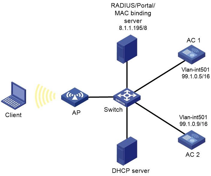
Network configuration
As shown in Figure 1, the AP and the client obtain IP addresses from the DHCP server. The IMC server acts as the portal authentication server, portal Web server, and RADIUS server.
Configure the devices to meet the following requirements:
· The AP associates with both ACs and the two ACs to back up each other. When the master AC (AC 1) fails, the backup AC (AC 2) takes over, and the AP can provide services correctly through the backup AC.
· Before passing portal authentication, the client can access only the portal Web server. After passing the authentication, the client can access other network resources.
· The AP forwards all the client traffic.
· The client can access network resources through any Layer 2 ports in its access VLAN without re-authentication.
Analysis
· To allow an authenticated user to access network resources on any Layer 2 ports in its access VLAN without re-authentication, you must enable the portal roaming feature.
· To assign interface GigabitEthernet 1/0/1 on the AP to VLAN 600 for local forwarding, you must edit the configuration file of the AP and then upload the file to the storage medium of the AC.
· For dual-link backup to operate correctly, you must configure manual AP or auto AP settings on both ACs. This ensures that the AP can establish CAPWAP tunnels with both ACs.
Restrictions and guidelines
When you configure remote portal MAC-trigger authentication for dual-link AC backup and local forwarding, follow these restrictions and guidelines:
· Use the actual serial ID of an AP to uniquely identify that AP.
· If you configure manual APs, make sure the manual APs configured on the two ACs have the same AP name and identifier (serial ID or MAC address).
· Portal authentication might fail if portal clients come online and go offline frequently during a short period. To resolve the issue, disable Rule ARP entry feature for portal clients.
· Make sure the two ACs have the same portal authentication settings, except for the portal Web server setting.
· Some clients are enabled with MAC randomization by default, which might cause seamless roaming failures. As a best practice, disable MAC randomization.
· You must upload the AP configuration file to both the master and backup ACs.
Procedures
Editing the AP configuration file
# Use a text editor to edit the AP configuration file, name the file map.txt, and then upload the file to the storage medium of the ACs. The file content and format are as follows:
system-view
vlan 600
interface gigabitethernet1/0/1
port link-type trunk
port trunk permit vlan 600
Configuring AC 1
1. Configure dual-link backup:
# Create VLAN 501 and VLAN-interface 501. Assign the VLAN interface an IP address. The AC will use this IP address to establish a CAPWAP tunnel with the AP.
<AC1> system-view
[AC1] vlan 501
[AC1-vlan501] quit
[AC1] interface vlan-interface 501
[AC1-Vlan-interface501] ip address 99.1.0.5 16
[AC1-Vlan-interface501] quit
# Create VLAN 600. This VLAN will be used for wireless client access.
[AC1] vlan 600
[AC1-vlan600] quit
# Configure GigabitEthernet 1/0/1 that connects AC 1 to the switch as a trunk port, and assign the port to VLANs 501 and 600.
[AC1] interface gigabitethernet 1/0/1
[AC1-GigabitEthernet1/0/1] port link-type trunk
[AC1-GigabitEthernet1/0/1] port trunk permit vlan 501 600
[AC1-GigabitEthernet1/0/1] quit
2. Configure a static route to the IMC server.
[AC1] ip route-static 8.0.0.0 255.0.0.0 99.1.0.100
3. Configure wireless services:
# Create service template st1 and enter its view.
[AC1] wlan service-template st1
# Specify the SSID as service.
[AC1-wlan-st-st1] ssid service
# Assign clients coming online through the service template to VLAN 600.
[AC1-wlan-st-st1] vlan 600
# Specify the AKM mode as PSK, and configure the preshared key as 12345678 in plain text.
[AC1-wlan-st-st1] akm mode psk
[AC1-wlan-st-st1] preshared-key pass-phrase simple 12345678
# Specify the cipher suite as CCMP and the security IE as RSN.
[AC1-wlan-st-st1] cipher-suite ccmp
[AC1-wlan-st-st1] security-ie rsn
# Configure the AP to forward client traffic. (Skip this step if the client data traffic forwarder is the AP by default.)
[AC1–wlan-st-st1] client forwarding-location ap
[AC1-wlan-st-st1] quit
4. Configure the AP:
|
|
NOTE: In large-scale networks, configure AP groups instead of single APs as a best practice. |
# Create AP ap1, and specify the AP name and serial ID.
[AC1] wlan ap ap1 model WA6320
[AC1-wlan-ap-ap1] serial-id 219801A28N819CE0002T
# Create AP group group1 and add AP ap1 to AP group group1.
[AC1] wlan ap-group group1
[AC1-wlan-ap-group-group1] ap ap1
# Set the AP connection priority to 7.
[AC1-wlan-ap-group-group1] priority 7
# Specify AC 2 as the backup AC for AC 1.
[AC1-wlan-ap-group-group1] backup-ac ip 99.1.0.9
# Enable master CAPWAP tunnel preemption.
[AC1-wlan-ap-group-group1] wlan tunnel-preempt enable
# Deploy configuration file map.txt to the AP in the AP model view of AP group group1.
[AC1-wlan-ap-group-group1] ap-model WA6320
[AC1-wlan-ap-group-group1-ap-model-WA6320] map-configuration map.txt
# Bind service template st1 to radio 2 in AP group group1.
[AC1-wlan-ap-group-group1-ap-model-WA6320] radio 2
[AC1-wlan-ap-group-group1-ap-model-WA6320-radio-2] service-template st1
# Enable radio 2.
[AC1-wlan-ap-group-group1-ap-model-WA6320-radio-2] radio enable
[AC1-wlan-ap-group-group1-ap-model-WA6320-radio-2] quit
[AC1-wlan-ap-group-group1-ap-model-WA6320] quit
[AC1-wlan-ap-group-group1] quit
5. Configure a RADIUS scheme:
# Create RADIUS scheme rs1.
[AC1] radius scheme rs1
# Specify the IP addresses of the primary authentication and accounting RADIUS servers.
[AC1-radius-rs1] primary authentication 8.1.1.195
[AC1-radius-rs1] primary accounting 8.1.1.195
# Specify shared keys for RADIUS authentication and accounting.
[AC1-radius-rs1] key authentication simple radius
[AC1-radius-rs1] key accounting simple radius
# Configure AC 1 to remove the ISP domain name from the usernames sent to the RADIUS servers.
[AC1-radius-rs1] user-name-format without-domain
[AC1-radius-rs1] nas-ip 99.1.0.5
[AC1-radius-rs1] quit
# Enable RADIUS session-control.
[AC1] radius session-control enable
6. Configure the authentication domain:
# Create domain dm1 and enter its view.
[AC1] domain dm1
# Configure the domain to use RADIUS scheme rs1 for authentication, authorization, and accounting.
[AC1-isp-dm1] authentication portal radius-scheme rs1
[AC1-isp-dm1] authorization portal radius-scheme rs1
[AC1-isp-dm1] accounting portal radius-scheme rs1
# Set the client idle timeout to 15 minutes and set the minimum threshold to 1024 bytes for clients in ISP domain dm1.
[AC1-isp-dm1] authorization-attribute idle-cut 15 1024
[AC1-isp-dm1] quit
7. Configure portal authentication:
# Create the portal authentication server newpt, specify the server IP address as 8.1.1.195, and set the destination UDP port number to 50100 for the AC to send unsolicited portal packets to the portal authentication server.
[AC1] portal server newpt
[AC1-portal-server-newpt] ip 8.1.1.195 key simple portal
[AC1-portal-server-newpt] port 50100
[AC1-portal-server-newpt] quit
# Configure the URL for the portal Web server newpt as http://8.1.1.195:8080/portal.
[AC1] portal web-server newpt
[AC1-portal-websvr-newpt] url http://8.1.1.195:8080/portal
[AC1-portal-websvr-newpt] quit
# Enable intra-VLAN roaming for portal users.
[AC1] portal roaming enable
# Disable the Rule ARP entry feature for portal clients.
[AC1] undo portal refresh arp enable
# Enable validity check on wireless portal clients.
[AC1] portal host-check enable
# Enable direct IPv4 portal authentication for service template st1.
[AC1] wlan service-template st1
[AC1-wlan-st-st1] portal enable method direct
# Configure the authentication domain for IPv4 portal users as dm1 on service template st1.
[AC1-wlan-st-st1] portal domain dm1
# Specify portal Web server newpt as the backup portal Web server on service template st1 for portal authentication.
[AC1-wlan-st-st1] portal apply web-server newpt
# On service template st1, configure the BAS-IP attribute as 99.1.0.5 for portal packets sent to the portal authentication server.
[AC1-wlan-st-st1] portal bas-ip 99.1.0.5
[AC1-wlan-st-st1] quit
# Configure IPv4-based portal-free rules to permit DNS server traffic.
[AC1] portal free-rule 1 destination ip any udp 53
[AC1] portal free-rule 2 destination ip any tcp 53
8. Configure MAC-trigger authentication:
# Create the MAC binding server mts and enter its view.
[AC1] portal mac-trigger-server mts
# Specify the IP address of the MAC binding server as 8.1.1.195.
[AC1-portal-mac-trigger-server-mts] ip 8.1.1.195
[AC1-portal-mac-trigger-server-mts] quit
# Specify the MAC binding server mts on service template st1.
[AC1] wlan service-template st1
[AC1-wlan-st-st1] portal apply mac-trigger-server mts
# Enable the service template.
[AC1-wlan-st-st1] service-template enable
[AC1-wlan-st-st1] quit
Configuring AC 2
1. Configure dual-link backup:
# Create VLAN-interface 501. Assign the VLAN interface an IP address. The AC will use this IP address to establish a CAPWAP tunnel with the AP.
<AC2> system-view
[AC2] vlan 501
[AC2-vlan501] quit
[AC2] interface Vlan-interface 501
[AC2-Vlan-interface501] ip address 99.1.0.9 16
[AC2-Vlan-interface501] quit
# Configure GigabitEthernet 1/0/1 that connects AC 2 to the switch as a trunk port, and assign the port to VLANs 501 and 600.
[AC2] interface gigabitethernet 1/0/1
[AC2-GigabitEthernet1/0/1] port link-type trunk
[AC2-GigabitEthernet1/0/1] port trunk permit vlan 501 600
[AC2-GigabitEthernet1/0/1] quit
# Create AP ap1, and specify the AP model and serial ID.
[AC2] wlan ap ap1 model WA6320
[AC2-wlan-ap-ap1] serial-id 219801A28N819CE0002T
[AC2-wlan-ap-ap1] quit
# Create AP group group1 and add AP ap1 to AP group group1.
[AC2] wlan ap-group group1
[AC2-wlan-ap-group-group1] ap ap1
# Set the AP connection priority to 5.
[AC2-wlan-ap-group-group1] priority 5
# Specify AC 1 as the backup AC for AC 2.
[AC2-wlan-ap-group-group1] backup-ac ip 99.1.0.5
# Enable master CAPWAP tunnel preemption.
[AC2-wlan-ap-group-group1] wlan tunnel-preempt enable
2. Configure AC 2 in the same way AC 1 was configured.
Configuring the switch
# Create VLAN 501. The VLAN will be used to forward traffic in the CAPWAP tunnels between the ACs and the AP.
<Switch> system-view
[Switch] vlan 501
[Switch-vlan501] quit
# Create VLAN 600. The VLAN will be used to forward client traffic.
[Switch] vlan 600
[Switch-vlan600] quit
# Create VLAN 2. The VLAN will be used to connect to the IMC server.
[Switch] vlan 2
[Switch-vlan2] quit
# Assign the interface that connects the switch to the IMC server to VLAN 2. (Details not shown.)
# Configure GigabitEthernet 1/0/1 that connects the switch to AC 1 as a trunk port, and assign the port to VLANs 501 and 600.
[Switch] interface gigabitethernet 1/0/1
[Switch-GigabitEthernet1/0/1] port link-type trunk
[Switch-GigabitEthernet1/0/1] port trunk permit vlan 501 600
[Switch-GigabitEthernet1/0/1] quit
# Configure GigabitEthernet 1/0/3 that connects the switch to AC 2 as a trunk port, and assign the port to VLANs 501 and 600.
[Switch] interface gigabitethernet 1/0/3
[Switch-GigabitEthernet1/0/3] port link-type trunk
[Switch-GigabitEthernet1/0/3] port trunk permit vlan 501 600
[Switch-GigabitEthernet1/0/3] quit
# Configure GigabitEthernet 1/0/2 that connects the switch to the AP as a trunk port, assign the port to VLANs 501 and 600, and set the PVID to 501.
[Switch] interface gigabitethernet 1/0/2
[Switch-GigabitEthernet1/0/2] port link-type trunk
[Switch-GigabitEthernet1/0/2] port trunk permit vlan 501 600
[Switch-GigabitEthernet1/0/2] port trunk pvid vlan 501
# Enable PoE.
[Switch-GigabitEthernet1/0/2] poe enable
[Switch-GigabitEthernet1/0/2] quit
# Configure GigabitEthernet 1/0/4 that connects the switch to the DHCP server as a trunk port, and assign the port to VLANs 501 and 600.
[Switch] interface gigabitethernet 1/0/4
[Switch-GigabitEthernet1/0/4] port link-type trunk
[Switch-GigabitEthernet1/0/4] port trunk permit vlan 501 600
[Switch-GigabitEthernet1/0/4] quit
# Assign an IP address to VLAN-interface 501.
[Switch] interface vlan-interface 501
[Switch-Vlan-interface501] ip address 99.1.0.100 255.255.0.0
[Switch-Vlan-interface501] quit
# Assign an IP address to VLAN-interface 600.
[Switch] interface vlan-interface 600
[Switch-Vlan-interface600] ip address 99.100.0.100 255.255.0.0
[Switch-Vlan-interface600] quit
# Assign an IP address to VLAN-interface 2. The IMC server will use this address as the gateway address.
[Switch] interface vlan-interface 2
[Switch-Vlan-interface2] ip address 8.1.1.190 255.0.0.0
[Switch-Vlan-interface2] quit
Configuring the DHCP server
Details not shown.
Configuring the IMC server
In this example, the IMC server runs IMC PLAT 7.3 (E0504), IMC EIA 7.3 (E0503), and IMC EIP 7.3 (E0503).
The IMC server configuration is the same for AC 1 and AC 2, except for the AC IP address. This section configures AC 1 as an example. Refer to AC 1 configuration when you configure AC 2 and remember to change the IP address setting for AC 2.
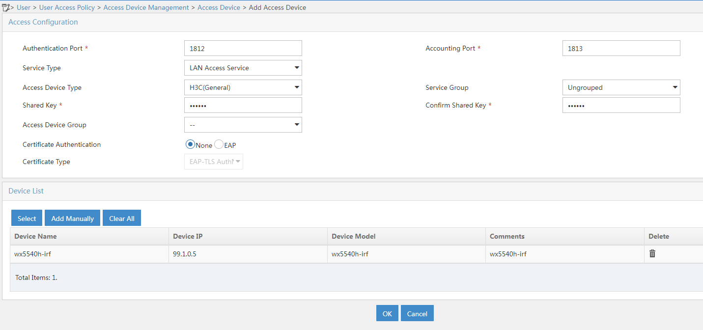
Configure the RADIUS server to add access devices
1. Log in to IMC and click the User tab.
2. From the navigation pane, select User Access Policy > Access Device Management > Access Device.
3. Click Add.
The Add Access Device page opens.
4. In the Access Configuration area, configure the following parameters:
¡ Enter radius in the Shared Key and Confirm Shared Key fields.
¡ Use the default values for other parameters.
5. In the Device List area, click Select or Add Manually to add the AC 1 at 99.1.0.5 as an access device.
6. Click OK.
Figure 2 Adding an access device
Configure the portal server:
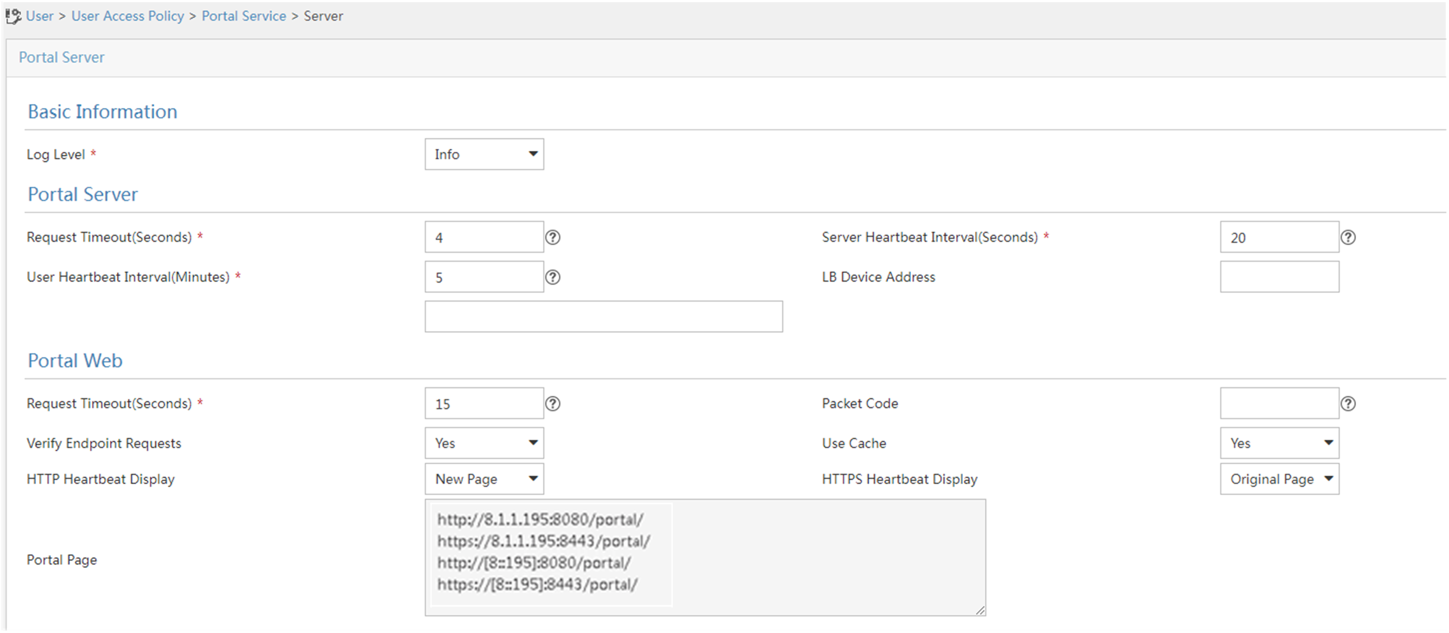
1. Configure portal authentication:
a. Click the User tab.
b. Select User Access Policy > Portal Service > Server from the navigation tree to open the portal server configuration page.
c. Configure the portal server parameters as needed.
This example uses the default settings.
d. Click OK.
Figure 3 Portal authentication server configuration
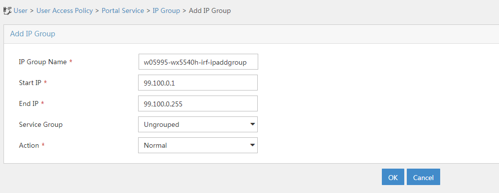
2. Configure the IP address group:
a. Select User Access Policy > Portal Service > IP Group from the navigation tree to open the portal IP address group configuration page.
b. Click Add to open the page as shown in Figure 4.
c. Enter the IP group name. In this example, the name is w05995-wx5540h-irf-ipaddgroup.
d. Enter the start IP address and end IP address of the IP group.
Make sure the client IP address is in the IP group.
e. Select a service group.
This example uses the default group Ungrouped.
f. Select Normal from the Action list.
g. Click OK.
Figure 4 Adding an IP address group
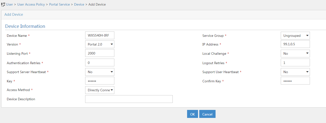
3. Add a portal device:
a. Select User Access Policy > Portal Service > Device from the navigation tree to open the portal device configuration page.
b. Click Add to open the page as shown in Figure 5.
c. Enter the device name. In this example, the name is WX5540H-IRF.
d. Specify the version as Portal 2.0.
e. Enter the IP address (99.1.0.5) of the AC's interface connected to the client.
f. Set whether to support the portal server heartbeat and user heartbeat functions.
In this example, select No for both Support Server Heartbeat and Support User Heartbeat.
g. Enter the key, which must be the same as that configured on the AC.
h. Select Directly Connected from the Access Method list.
i. Use the default settings for other parameters.
j. Click OK.
Figure 5 Adding a portal device
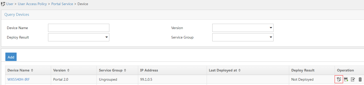
4. Associate the portal device with the IP address group:
a. As shown in Figure 6,
click the Port Group Information Management icon ![]() for the device to
open the port group configuration page.
for the device to
open the port group configuration page.
b. Click Add to open the page as shown in Figure 7.
c. Enter the port group name. In this example, the name is w05995-wx5540h-irf-portgroup.
d. Select the configured IP address group.
The IP address used by the user to access the network must be within this IP address group.
e. Select Supported for Transparent Authentication.
f. Use the default settings for other parameters.
g. Click OK.
h. From the navigation tree, select Intelligent Portal Management > User Management > Users.

5. Select User Access Policy > Service Parameters > Validate System Configuration from the navigation tree to make the configurations take effect.
Configuring the MAC binding server
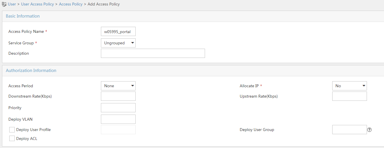
1. Add an access policy:
a. Select User Access Policy > Access Policy from the navigation tree to open the access policy page.
b. Click Add to open the page as shown in Figure 8.
c. Enter the access policy name. In this example, the name is w05995_portal.
d. Select a service group.
e. Use the default settings for other parameters.
f. Click OK.
Figure 8 Adding an access policy
2. Add an access service:
a. Select User Access Policy > Access Service from the navigation tree to open the access service page.
b. Click Add to open the page as shown in Figure 9.
c. Enter the service name. In this example, the service name is w05995_portal.
d. Select the Transparent Authentication on Portal Endpoints option.
e. Use the default settings for other parameters.
f. Click OK.
Figure 9 Adding an access service

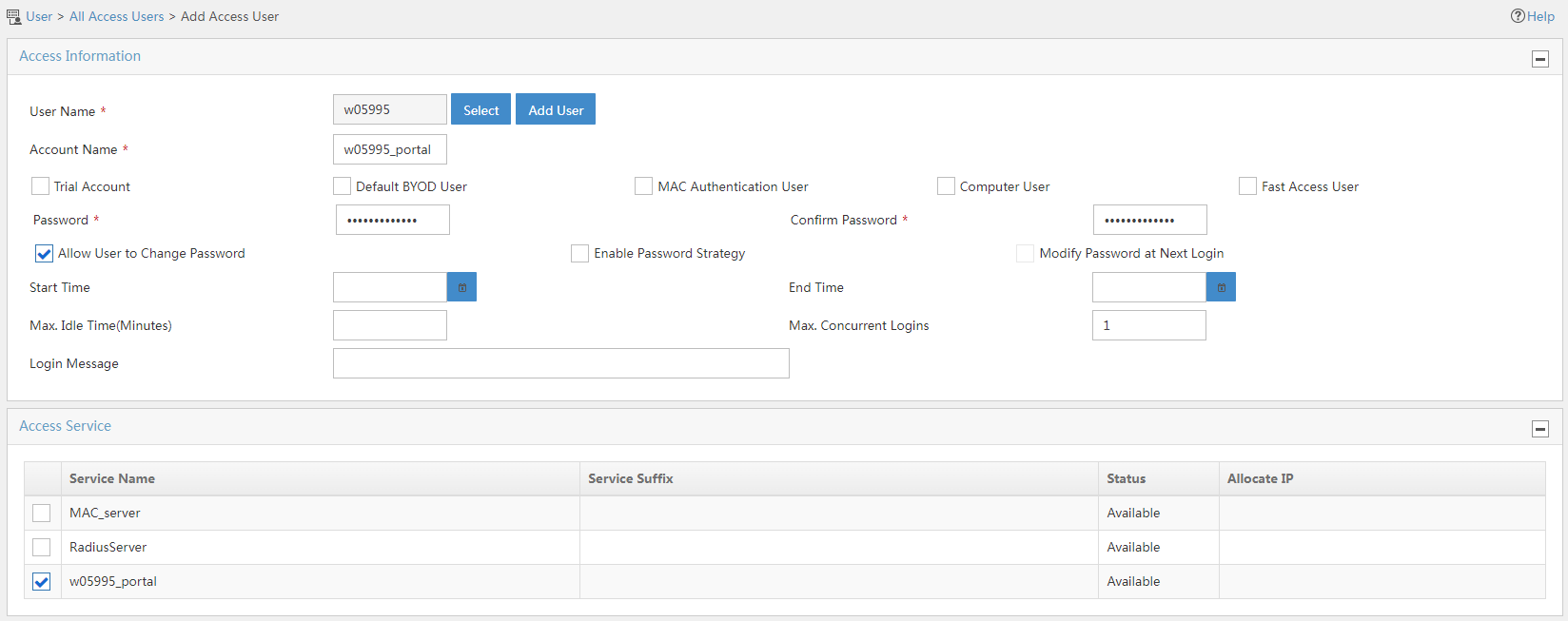
3. Add an access user:
a. Select Access User > All Access Users from the navigation tree to open the access user page.
b. Click Add to open the page as shown in Figure 10.
c. Select or add an access user. In this example, the account name is w05995.
d. Set the password. In this example, the password is w05995_portal.
e. Select Enable Password Strategy.
f. Retain the default settings for other parameters.
g. Select the configured service.
h. Click OK.
Figure 10 Adding an access user
4. Configure system parameters:
a. Select User Access Policy > Service Parameters > System Settings from the navigation tree to open the system settings page.
b. Click the Configure
icon ![]() for User Endpoint Settings to open the page as shown in Figure 11.
for User Endpoint Settings to open the page as shown in Figure 11.
c. Enable Transparent MAC Authentication.
d. Select whether to enable transparent portal authentication on non-smart devices.
In this example, select Enable for Non-Terminal Authentication.
e. Click OK.
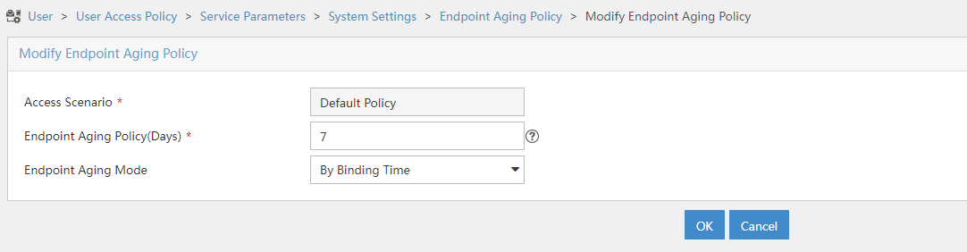
f. Click the Configure
icon ![]() for Endpoint Aging Time to open the page as shown in Figure 12.
for Endpoint Aging Time to open the page as shown in Figure 12.
g. Set the endpoint aging time as needed.
This example uses the default value.
Figure 11 Configuring user endpoint settings

Figure 12 Setting the endpoint aging time
5. Select User Access Policy > Service Parameters > Validate System Configuration from the navigation tree to make the configurations take effect.
Verifying the configuration
Verifying dual-link backup configuration
# Make the AP come online.
# Verify that the AP first associates with AC 1. Shut down VLAN-interface 501 on AC 1, wait 3 minutes, and verify that the AP associates with AC 2 and the AP state on AC 2 is R/M.
[AC2] display wlan ap all
Total number of APs: 1
Total number of connected APs: 1
Total number of connected manual APs: 1
Total number of connected auto APs: 0
Total number of connected common APs: 1
Total number of connected WTUs: 0
Total number of inside APs: 0
Maximum supported APs: 10
Remaining APs: 9
Total AP licenses: 10
Local AP licenses: 10
Server AP licenses: 0
Remaining local AP licenses: 9
Sync AP licenses: 0
AP information
State : I = Idle, J = Join, JA = JoinAck, IL = ImageLoad
C = Config, DC = DataCheck, R = Run, M = Master, B = Backup
AP name APID State Model Serial ID
ap1 1 R/M WA6320 219801A28N819CE0002T
# Bring up VLAN-interface 501 on AC 1. Verify that the AP state becomes R/M on AC 1 and R/B on AC 2.
[AC1] display wlan ap all
Total number of APs: 1
Total number of connected APs: 1
Total number of connected manual APs: 1
Total number of connected auto APs: 0
Total number of connected common APs: 1
Total number of connected WTUs: 0
Total number of inside APs: 0
Maximum supported APs: 10
Remaining APs: 9
Total AP licenses: 10
Local AP licenses: 10
Server AP licenses: 0
Remaining local AP licenses: 9
Sync AP licenses: 0
AP information
State : I = Idle, J = Join, JA = JoinAck, IL = ImageLoad
C = Config, DC = DataCheck, R = Run, M = Master, B = Backup
AP name APID State Model Serial ID
ap1 1 R/M WA6320 219801A28N819CE0002T
[AC2] display wlan ap all
Total number of APs: 1
Total number of connected APs: 1
Total number of connected manual APs: 1
Total number of connected auto APs: 0
Total number of connected common APs: 1
Total number of connected WTUs: 0
Total number of inside APs: 0
Maximum supported APs: 10
Remaining APs: 9
Total AP licenses: 10
Local AP licenses: 10
Server AP licenses: 0
Remaining local AP licenses: 10
Sync AP licenses: 0
AP information
State : I = Idle, J = Join, JA = JoinAck, IL = ImageLoad
C = Config, DC = DataCheck, R = Run, M = Master, B = Backup
AP name APID State Model Serial ID
ap1 1 R/B WA6320 219801A28N819CE0002T
Verifying portal MAC-trigger authentication configuration
# Display MAC binding server configuration.
[AC1] display portal mac-trigger-server name mts
Portal mac trigger server name: mts
Version : 1.0
Server type : IMC
IP : 8.1.1.195
Port : 50100
VPN instance : Not configured
Aging time : 300 seconds
Free-traffic threshold : 0 bytes
NAS-Port-Type : Not configured
Binding retry times : 3
Binding retry interval : 1 seconds
Authentication timeout : 3 minutes
A user can perform portal authentication through a Web browser. Before passing the authentication, the user can access only the authentication page http://192.168.0.111:8080/portal. All Web requests from the user will be redirected to the authentication page. After passing the authentication, the user can access other network resources.
For the first portal authentication, the user is required to enter the username and password.
# Display portal user information.
[AC1] display portal user all
Total portal users: 1
Username: w05995_portal
AP name: ap1
Radio ID: 2
SSID: service
Portal server: newpt
State: Online
VPN instance: N/A
MAC IP VLAN Interface
a89c-ed90-7730 99.100.0.12 600 WLAN-BSS2/0/2121
Authorization information:
DHCP IP pool: N/A
User profile: N/A
Session group profile: N/A
ACL number: N/A
Inbound CAR: N/A
Outbound CAR: N/A
When the user goes offline and then accesses the network again, the user does not need to enter the authentication username and password.
# Display portal user information.
[AC1] display portal user all
Total portal users: 1
Username: A8:9C:ED:90:77:30
AP name: ap1
Radio ID: 2
SSID: service
Portal server: newpt
State: Online
VPN instance: N/A
MAC IP VLAN Interface
a89c-ed90-7730 99.100.0.12 600 WLAN-BSS2/0/2121
Authorization information:
DHCP IP pool: N/A
User profile: N/A
Session group profile: N/A
ACL number: N/A
Inbound CAR: N/A
Outbound CAR: N/A
Configuration files
· AC 1:
#
vlan 501
#
vlan 600
#
wlan service-template st1
ssid service
vlan 600
client forwarding-location ap
akm mode psk
preshared-key pass-phrase cipher $c$3$oLf6pOZ6bxrf25nodjOJKYEfnZ6g6ErccHyQ
cipher-suite ccmp
security-ie rsn
portal enable method direct
portal domain dm1
portal bas-ip 99.1.0.5
portal apply web-server newpt
portal apply mac-trigger-server mts
service-template enable
#
interface Vlan-interface501
ip address 99.1.0.5 255.255.0.0
#
interface GigabitEthernet1/0/1
port link-type trunk
port trunk permit vlan 1 501 600
#
ip route-static 8.0.0.0 8 99.1.0.100
#
radius scheme rs1
primary authentication 8.1.1.195
primary accounting 8.1.1.195
key authentication cipher $c$3$/Mc+yQtK3k6E3L0TtJth+7Pel1EBrSZAmg==
key accounting cipher $c$3$WoQkH/FblsUGadr043yY0MGAPHWTIQvUdA==
user-name-format without-domain
nas-ip 99.1.0.5
#
domain dm1
authorization-attribute idle-cut 15 1024
authentication portal radius-scheme rs1
authorization portal radius-scheme rs1
accounting portal radius-scheme rs1
#
portal host-check enable
portal free-rule 1 destination ip any udp 53
portal free-rule 2 destination ip any tcp 53
#
portal web-server newpt
url http://8.1.1.195:8080/portal
#
portal server newpt
ip 8.1.1.195 key cipher $c$3$GZf8+GypB2tLYA25pKOLrJu3quh+vnFElQ==
#
portal mac-trigger-server mts
ip 8.1.1.195
#
wlan ap-group group1
priority 7
wlan tunnel-preempt enable
backup-ac ip 99.1.0.9
ap ap1
ap-model WA6320
map-configuration flash:/map.txt
radio 1
radio 2
radio enable
service-template st1
#
wlan ap ap1 model WA6320
serial-id 219801A28N819CE0002T
#
· AC 2:
Similar as that on AC 1. (Details not shown.)
· Switch:
#
vlan 2
#
vlan 501
#
vlan 600
#
interface Vlan-interface2
ip address 8.1.1.190 255.0.0.0
#
interface Vlan-interface501
ip address 99.1.0.100 255.255.0.0
#
interface Vlan-interface600
ip address 99.100.0.100 255.255.0.0
#
interface GigabitEthernet1/0/1
port link-type trunk
port trunk permit vlan 1 501 600
#
interface GigabitEthernet1/0/2
port link-type trunk
port trunk permit vlan 1 501 600
port trunk pvid vlan 501
poe enable
#
interface GigabitEthernet1/0/3
port link-type trunk
port trunk permit vlan 1 501 600
#
interface GigabitEthernet1/0/4
port link-type trunk
port trunk permit vlan 1 501 600
#
Related documentation
· AP Management Command Reference in H3C Access Controllers Command References
· AP Management Configuration Guide in H3C Access Controllers Configuration Guides
· Portal Authentication Command Reference in H3C Access Controllers Command References
· Portal Authentication Configuration Guide in H3C Access Controllers Configuration Guides
· WLAN Access Command Reference in H3C Access Controllers Command References
· WLAN Access Configuration Guide in H3C Access Controllers Configuration Guides
· WLAN High Availability Command Reference in H3C Access Controllers Command References
· WLAN High Availability Configuration Guide in H3C Access Controllers Configuration Guides
