- Table of Contents
-
- H3C SR8800-X Router Series Installation Guide-5W105
- 00-Preface
- 01-Chapter 1 Preparing for Installation
- 02-Chapter 2 Installing the Router
- 03-Chapter 3 Installing FRUs
- 04-Chapter 4 Connecting Your Router to the Network
- 05-Chapter 5 Troubleshooting
- 06-Chapter 6 Replacement Procedures
- 07-Appendix A Chassis Views and Technical Specifications
- 08-Appendix B FRUs and Compatibility Matrixes
- 09-Appendix C LEDs
- 10-Appendix D Slot arrangement and port numbering
- 11-Appendix E Cables
- 12-Appendix F Engineering Labels for Cables and Devices
- 13-Appendix G Cabling Recommendations
- 14-Appendix H Repackaging the Router
- Related Documents
-
| Title | Size | Download |
|---|---|---|
| 14-Appendix H Repackaging the Router | 4.70 MB |
Appendix H Repackaging the router
Removing cables from the router
Removing the twisted pair and optical fiber
Repackaging the router accessories
Repackaging the router chassis
Removing the chassis from the rack
Removing cable management brackets and mounting brackets (only for the SR8812-X router)
Repackaging the router chassis
Appendix H Repackaging the router
This chapter describes how to repackage the router chassis, power supply, card, mounting bracket, cable management bracket, and air filter.
Removing cables from the router
Before repackaging the router, remove all cables such as the power cord, console cable, twisted pair, optical fiber, and grounding cable from the router.
Removing the power cord
1. Switch off the circuit breakers at the input end of all power cords.
2. Wear an ESD wrist strap, and make sure it has a good skin contact and is correctly grounded.
For more information, see "Attaching an ESD wrist strap."
3. Remove the power cord plug:
¡ AC power cord—Remove the cable tie that secures the power cord, and then pull out the plug.
¡ DC power cord—Remove the cable tie that secures the power cord, loosen the fastening screw on the power cord, and then pull out the plug.
Removing the console cable
1. Pull the RJ-45 connector of the console cable out from the console port of the router.
2. Pull the DB-9 connector of the console cable out from the serial port of the PC.
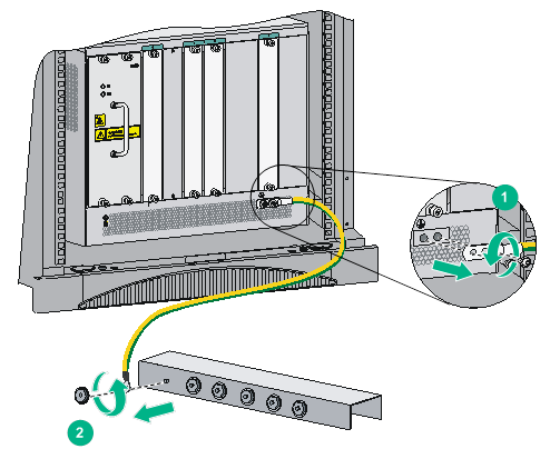
Removing the grounding cable
1. Loosen the two screws at the grounding holes of the chassis, and then remove the grounding cable from the chassis.
2. Use a lever to loosen the hex nut on the grounding post of the grounding strip, and remove the other end of the grounding cable (with a ring terminal) from the grounding post.
Figure 1 Removing the grounding cable
Removing the twisted pair and optical fiber
You must remove twisted pairs and optical fibers from all the interfaces of the router.
|
|
NOTE: After pulling out an optical fiber from an optical transceiver module, cover the connector of the optical fiber with a dust cap to keep the connector clean. |
Repackaging the router accessories
Repackaging the power supply
|
|
WARNING! Before removing a power supply, switch off the circuit breakers at the input end of all power cords, and remove all the power cords to avoid device damage and bodily injury. |
1. Prepare the packing bag and box of the power supply. Make sure the bag is clean, dry, and not damaged.
2. Remove all power supplies from the chassis, and then install filler panels to the empty slots.
For information about how to remove a power supply and install a filler panel, see "Replacing a power supply."
3. Put the power supply into the bag.
4. Put the packed power supply and power cord into the box. Place the power supply in a correct direction onto the foam cushion in the box; otherwise, the power supply cannot be completely seated into the foam cushion.
Repackaging the card
1. Prepare the anti-static bag and box of the card. Make sure the bag is clean, dry, and not damaged.
2. Remove the transceiver modules from the card. If no transceiver module is installed on the card, go to the next step.
For information about how to remove a transceiver module, see "Replacing a transceiver module."
3. Remove all cards from the chassis slots, and install filler panels to the empty slots.
For information about how to remove a card and install a filler panel, see "Replacing a card"
4. Put the card into the anti-static bag.
The switching fabric modules for the routers (except the SR8804-X router) each are provided with a protection box. Put the switching fabric module into the protection box, and then put the box into the anti-static bag.
5. Put the packed card into the box, and tape the flaps of the box with packing tape. Place the card in a correct direction onto the foam cushion in the box; otherwise, the power supply cannot be completely seated into the foam cushion.
Repackaging the router chassis
Removing the chassis from the rack
The router is heavy. If possible, use a mechanical lift to move the router.
To remove the chassis from the rack:
1. Prepare the wooden box and packing bag of the chassis. Make sure the box and bag are clean, dry, and not damaged.
2. Remove the top cap and side panels from the wooden box, and put the pallet base to a proper place.
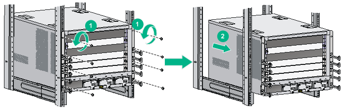
3. Use a Phillips screwdriver to loosen the screws that attach the mounting brackets to the rack.
4. Use a minimum of two people to slide the chassis outwards along the slide rails. When most part of the chassis is removed from the slide rails, lift up the chassis by holding the handles at the chassis sides to completely remove the chassis from the rack.
5. Put the chassis onto the pallet base of the wooden box.
Figure 2 Removing the chassis from the rack
Removing the air filter
1. Prepare the packing bag of the air filter. Make sure the bag is clean, dry, and not damaged.
2. Remove the air filter from the side of the chassis.
For information about how to remove an air filter, see "Replacing an air filter."
3. Put the air filter into the bag.
Removing cable management brackets and mounting brackets (only for the SR8812-X router)
Before repackaging the SR8812-X router chassis, remove the cable management brackets and mounting brackets from the chassis.
Removing the mounting brackets
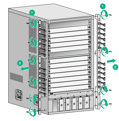
1. Prepare the packing box of the mounting brackets. Make sure the box is clean, dry, and not damaged.
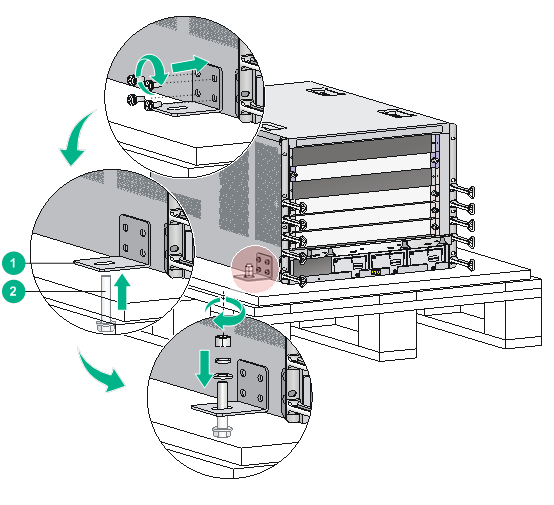
2. As shown in Figure 3, use a Phillips screwdriver to loosen the screws that attach the mounting brackets to the chassis, and then remove the mounting brackets.
3. Put the mounting brackets into the box.
Figure 3 Removing the mounting brackets from the chassis
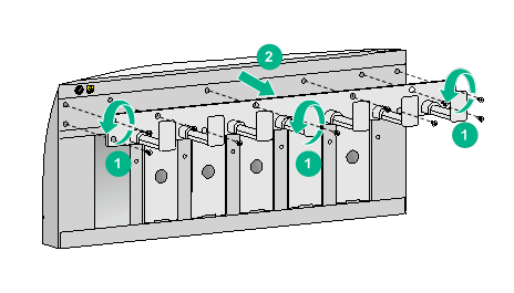
Removing the cable management brackets
1. Prepare the packing bag of the cable management brackets. Make sure the bag is clean, dry, and not damaged.
2. Use a Phillips screwdriver to loosen the screws that attach the cable management brackets to the chassis, and then remove the cable management brackets.
3. Put the cable management brackets into the bag.
Figure 4 Removing the cable management brackets
Repackaging the router chassis
Repackaging the router chassis (only for the SR8812-X router)
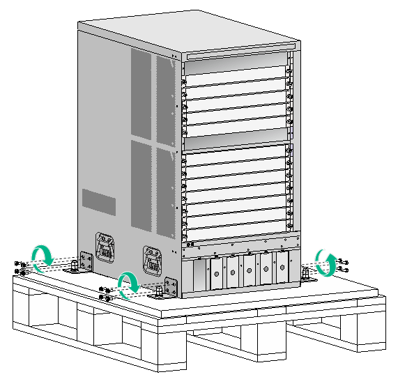
1. As shown in Figure 5, align the screw holes on the two sides of the chassis bottom to the L-type brackets on the pallet base of the wooden box.
2. Screw in the screws shipped with your router and fasten.
Figure 5 Repackaging the router chassis
3. Cover the chassis with the packing bag, and then tape the bag to the base pallet.
4. Install the side panels to the base pallet.
5. Put the accessories box and mounting bracket box into the wooden box—at the clearance between the chassis and the wooden panel.
6. Cover the foam cushion to the chassis top, and make sure the surface of the foam cushion aligns to the upper rims of the wooden box. Cover the foam cushion in a correct direction; otherwise, the foam cushion cannot be completely placed in the wooden box.
7. Cover the top cap to the wooden box, and then connect the panels with corro clips on each seam.
Repackaging the router chassis (router models other than SR8812-X)
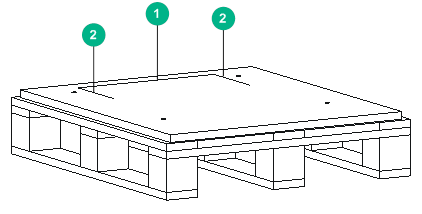
1. Align the left, right, and rear edges of the chassis bottom with the left, right, and rear positioning lines respectively on the wooden pallet base.
Figure 6 wooden pallet base
|
(1) Rear positioning line |
(2) Left and right positioning lines |
2. Use screws to attach L-type brackets to the chassis.
3. Align the mounting holes on the L-type brackets with the mounting holes in the wooden pallet base.
4. Use the L-type brackets to attach the chassis to the wooden pallet base.
¡ For the SR8816-X router, place the flat washer and spring washer in sequence onto each L-type bracket and insert and fasten the bracket into the mounting hole in the wooden pallet base.
¡ For the SR8804-X, SR8808-X, and SR8808H-X routers, perform the following steps:
a) Attach a washer to a bolt.
b) Insert the bolt through the mounting hole from the bottom of the wooden pallet base until the bolt reaches out the mounting hole from the top of the wooden pallet base.
c) Attach another washer and two nuts to the bolt in sequence.
d) Fasten the nuts.
Figure 7 Using the L-type brackets to secure the chassis to the wooden pallet base (SR8804-X)
|
(1) L-type bracket |
(2) Bolt |
5. Cover the chassis with the packing bag from the top down, and then tape the bag to the plastic cover of pallet base.
6. Cover the foam cushion to the chassis top, and make sure the mounting brackets seat into the internal notches of the foam cushion.
7. Put the accessories box in the notch in the top middle of the foam cushion.
8. Use a cardboard box or a wooden box to package the chassis.
¡ For the SR8816-X router, attach the four wooden side panels of the wooden box to the pallet base.
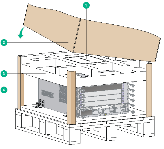
¡ For the SR8804-X, SR8808-X, and SR8808H-X routers, erect one paper angle bead along each vertical edge of the chassis, and use the cardboard box to cover the chassis from top down with the silkscreen side facing the front panel of the chassis.
9. Cover the top cap of the cardboard box or wooden box. Skip this step for the SR8804-X router.
¡ For the SR8816-X router, cover the top cap to the wooden box, and then connect the panels with corro clips on each seam.
¡ For the SR8808-X and SR8808H-X routers, cover the top cap to the cardboard box.
Figure 8 Repackaging the chassis (SR8804-X)
|
(1) Accessories box |
(2) Cardboard box |
|
(3) Foam cushion |
(4) Paper angle bead |
