- Table of Contents
-
- H3C SR8800-X Router Series Installation Guide-5W105
- 00-Preface
- 01-Chapter 1 Preparing for Installation
- 02-Chapter 2 Installing the Router
- 03-Chapter 3 Installing FRUs
- 04-Chapter 4 Connecting Your Router to the Network
- 05-Chapter 5 Troubleshooting
- 06-Chapter 6 Replacement Procedures
- 07-Appendix A Chassis Views and Technical Specifications
- 08-Appendix B FRUs and Compatibility Matrixes
- 09-Appendix C LEDs
- 10-Appendix D Slot arrangement and port numbering
- 11-Appendix E Cables
- 12-Appendix F Engineering Labels for Cables and Devices
- 13-Appendix G Cabling Recommendations
- 14-Appendix H Repackaging the Router
- Related Documents
-
| Title | Size | Download |
|---|---|---|
| 02-Chapter 2 Installing the Router | 5.43 MB |
Confirming installation preparations
Attaching slide rails and cage nuts to the rack
Installing cable management brackets and mounting brackets (for the SR8812-X router)
Installing cable management brackets
(Optional) Installing an air filter
Installing an air filter for an SR8808-X router
Installing an air filter for an SR8808H-X/an SR8816-X router
Installing an air filter for an SR8800-X router
Mounting the router in the rack
Grounding the router with a grounding strip
Grounding the router through the PE wire of an AC power supply
Grounding the router through the RTN wire of a DC power supply
Installing the router
This section describes the procedure for installing the router.
|
|
NOTE: · The chassis and component views in this section are for illustration only. · Keep the packages of the router and components for future use. |
Confirming installation preparations
Before you install the router, verify that:
· You have read the chapter "Preparing for installation" carefully and the installation site meets all the requirements.
· A 19-inch rack is ready for use if you are to install the router in a rack. For how to install a rack, see the rack installation guide.
· The rack is sturdy and is reliably grounded.
· No debris or obstacles exist inside or around the rack.
· Make sure the rack has enough space to accommodate the router. As a best practice to maintain the rack stability, install the router at the rack bottom. To mount multiple devices in a rack, install the heavier devices at the bottom.
· The total height of the devices to be installed is no higher than the available installation height of the rack and enough clearance is reserved for cable routing.
· The router is ready for installation and has been carried to a place near the rack and convenient for moving.
Attaching slide rails and cage nuts to the rack
Installing slide rails
Before you mount the router in a rack, install slide rails on the rack. As a best practice, purchase slide rails from H3C. Table 1 describes the slide rails available for the router. For information about installing the slide rails, see the installation guide shipped with the slide rails.
If the rack has slide rails installed, skip this section.
|
|
IMPORTANT: · Select slide rails for the router based on the total chassis weight. · To rack-mount the SR8816-X router, reserve a 2 RU space between the router (including slide rails) and the rack bottom. |
Table 1 Slide rails available for the router
|
Router model |
Chassis weight with full configuration |
Available slide rails |
|||
|
Slide rail model |
Max. load-bearing capacity |
Adjustment range |
Occupied space |
||
|
SR8804-X |
76 kg (167.55 lb) |
LSXM1BSR |
450 kg (992.06 lb) |
630 to 900 mm (24.80 to 35.43 in) |
1 RU |
|
LSTM1KSGD0 |
280 kg (617.28 lb) |
300 to 500 mm (11.81 to 19.69 in) |
2 RU |
||
|
LSTM2KSGD0 |
360 kg (793.65 lb) |
500 to 800 mm (19.69 to 31.50 in) |
2 RU |
||
|
SR8808-X (one fan tray) |
120 kg (264.55 lb) |
LSXM1BSR |
450 kg (992.06 lb) |
630 to 900 mm (24.80 to 35.43 in) |
1 RU |
|
LSTM1KSGD0 |
280 kg (617.28 lb) |
300 to 500 mm (11.81 to 19.69 in) |
2 RU |
||
|
LSTM2KSGD0 |
360 kg (793.65 lb) |
500 to 800 mm (19.69 to 31.50 in) |
2 RU |
||
|
SR8808-X (two fan trays) |
170 kg (374.78 lb) |
LSXM1BSR |
450 kg (992.06 lb) |
630 to 900 mm (24.80 to 35.43 in) |
1 RU |
|
LSTM1KSGD0 |
280 kg (617.28 lb) |
300 to 500 mm (11.81 to 19.69 in) |
2 RU |
||
|
LSTM2KSGD0 |
360 kg (793.65 lb) |
500 to 800 mm (19.69 to 31.50 in) |
2 RU |
||
|
SR8812-X |
174 kg (383.60 lb) |
LSXM1BSR |
450 kg (992.06 lb) |
630 to 900 mm (24.80 to 35.43 in) |
1 RU |
|
LSTM1KSGD0 |
280 kg (617.28 lb) |
300 to 500 mm (11.81 to 19.69 in) |
2 RU |
||
|
LSTM2KSGD0 |
360 kg (793.65 lb) |
500 to 800 mm (19.69 to 31.50 in) |
2 RU |
||
|
SR8808H-X |
245 kg (540.12 lb) |
LSXM1BSR |
450 kg (992.06 lb) |
630 to 900 mm (24.80 to 35.43 in) |
1 RU |
|
LSTM1KSGD0 |
280 kg (617.28 lb) |
300 to 500 mm (11.81 to 19.69 in) |
2 RU |
||
|
LSTM2KSGD0 |
360 kg (793.65 lb) |
500 to 800 mm (19.69 to 31.50 in) |
2 RU |
||
|
SR8816-X |
440 kg (970.02 lb) |
LSXM1BSR |
450 kg (992.06 lb) |
630 to 900 mm (24.80 to 35.43 in) |
1 RU |
|
LSTM2KSGD0 |
360 kg (793.65 lb) |
500 to 800 mm (19.69 to 31.50 in) |
2 RU |
||
Installing cage nuts
Before mounting the chassis in the rack, attach cage nuts to the front rack posts.
1. Align the bottom edge of a mounting bracket with the top flange of a slide rail. Then mark the cage nut installation holes on the front rack post.
If the mounting brackets are already installed, you can use a pattern tool to record the installation holes of the mounting brackets and mark the cage nut holes accordingly.
2. Install cage nuts into the marked square holes on the front rack posts.
Figure 1 Installing cage nuts (SR8812-X)
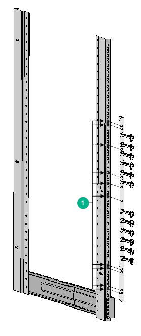
|
(1) Installation holes for cage nuts |
Installing cable management brackets and mounting brackets (for the SR8812-X router)
Before installing the SR8812-X router in the rack, install the cable management brackets and mounting brackets shipped with the router. The cable management brackets and mounting brackets for other models have been installed when shipped. Cable management brackets are used for cabling the router, and mounting brackets are used for attaching the chassis to the rack.
Installing cable management brackets
Cable management brackets include signal cable management brackets and power cord management brackets.
The SR8812-X router comes with the signal cable management brackets attached to the mounting brackets. You need to install the power cord management bracket for the router.
To install the power cord management bracket:
1. Unpack the power cord management bracket.
2. Place the power cord management bracket against the chassis and align the mounting holes in the bracket with the installation holes in the chassis.
3. Use screws to secure the power cord management bracket to the chassis.
Figure 2 Installing a power cord management bracket
Installing mounting brackets
Before installing the router in the rack, attach the mounting brackets to the chassis.
The left and right mounting brackets available for the router are labeled with L and R marks, respectively.
To install the mounting brackets, face the front of the router, and attach the left and right mounting brackets to the two sides of the router, as shown in Figure 3.
Figure 3 Installing the mounting brackets
(Optional) Installing an air filter
Air filters are optional components and include chassis air filters and cabinet air filters. The applicable air filters vary by router model.
Air filter is an optional component for the router. If you have ordered an air filter, install it before mounting the router in the rack.
· SR8808-X—Use a chassis air filter, which is installed over the air inlet vents at the bottom front of the chassis. Before installing an air filter, install the power cord management bracket for the chassis.
· SR8808H-X/SR8816-X—Use a cabinet air filter, which is attached to the interior side of the cabinet door.
· Other models—Use a chassis air filter, which is installed at the left of the chassis.
Installing an air filter for an SR8808-X router
1. Place the air filter over the inlet vents at the front panel bottom, and then align the captive screws on the air filter with the screw holes in the chassis.
2. Faster the captive screws.
Figure 4 Installing an air filter
Installing an air filter for an SR8808H-X/an SR8816-X router
To prevent dust for an SR8808H-X/an SR8816-X router, install an air filter on the cabinet. For a cabinet with a double-leaf door, cut the air filter into two halves based on the door size and install the air filter on the two door leaves.
To install an air filter on a cabinet:
1. As shown in Figure 5, paste air filter securing strips along the edge of the interior side of the cabinet door at a location 1 to 2 cm (0.39 to 0.79 in) away from the perforation holes. For a large-area single-leaf door, attach more securing strips.
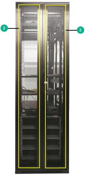
Figure 5 Attaching air filter securing strips
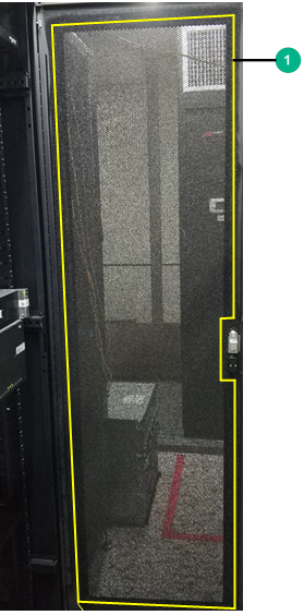
|
(1) Securing strip installation position on a single-leaf door |
|
(2) Securing strip installation position on a double-leaf door |
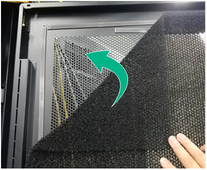
2. Press the air filter onto the securing strips to cover the entire cabinet door.
Figure 6 Pasting the air filter onto the securing strips
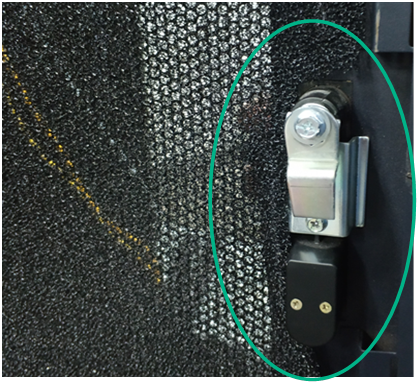
3. Cut off the excess parts at locations such as the door lock location.
Figure 7 Cutting off the excess parts
4. Press the air filter again to ensure that it is attached to the securing strips tightly.
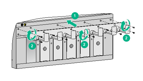
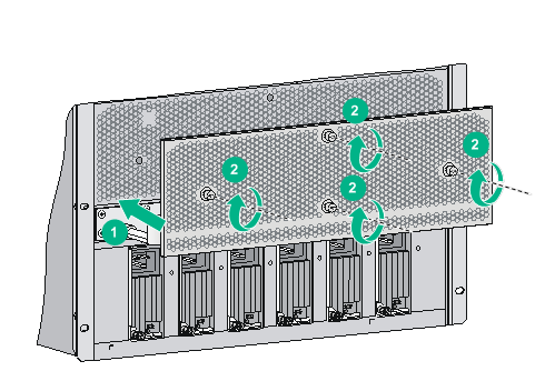
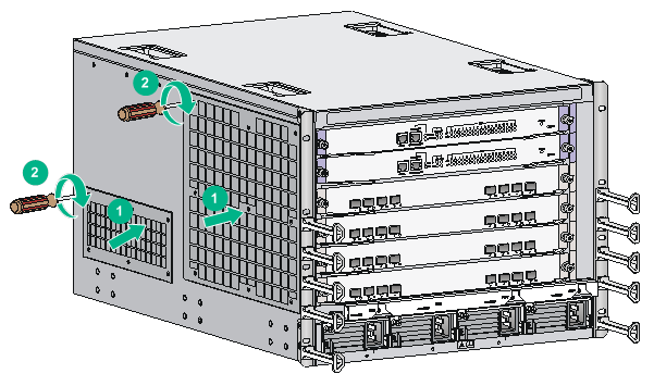
Installing an air filter for an SR8800-X router
1. Place the air filter over the inlet vents on the left panel of the chassis, and then align the captive screws on the air filter with the screw holes in the chassis.
2. Fasten the captive screws.
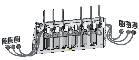
Figure 8 Installing an air filter
Mounting the router in the rack
|
|
WARNING! · Do not hold the handle of a fan tray or power module, air vents, or the handle on the real panel to move the router. Doing so might cause equipment damage or even bodily injury. · The router is heavy. As a best practice, use a mechanical lift to move it. · After placing the router on the slide rails, do not leave go of your hands immediately because this might tip the router, damaging the router or even causing bodily injury. |
This task requires a minimum of two people.
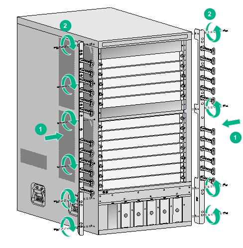
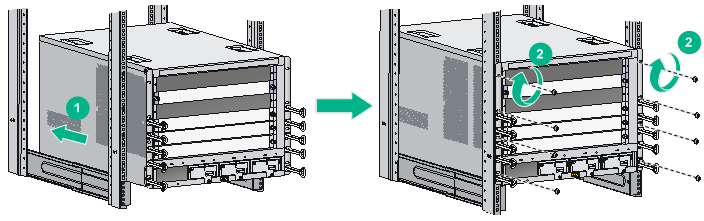
To mount the router in the rack:
1. Move the chassis to face the rear of the chassis towards the front of the rack.
2. Lift the router by using the handles or supporting the bottom of the chassis until the bottom of the router is a little higher than the slide rails on the rack.
3. Place the router on the slide rails and slide the router along the slide rails until the mounting brackets on the router touch the front rack posts.
4. Attach the chassis to the rack with mounting screws.
Figure 9 Installing the chassis in the rack
If the mounting holes in the mounting brackets cannot align with the cage nuts on the rack, verify that the bottom edge of the slide rail aligns with the middle of the narrower metal area between holes and that the cage nuts are installed in the correct holes.
Grounding the router
|
|
CAUTION: Before you use the router, connect the grounding cable correctly to guarantee lightning protection and anti-interference of the router. |
Grounding the router with a grounding strip
|
|
CAUTION: · Use the supplied grounding cable (yellow-green grounding cable). · Connect the grounding cable to the grounding system in the equipment room. Do not connect it to a fire main or lightning rod. |
If a grounding strip is available at the installation site, connect the grounding cable through the grounding strip.
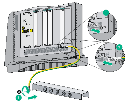
To connect the grounding cable:
1. Unpack the grounding cable.
The grounding cable provided with the router is compliant with the NEBS standards.
2. Remove the grounding screws from the grounding holes at the rear of the chassis.
3. Fasten the grounding screws, which are attached with the dual-hole terminals of the grounding cable, into the grounding holes of the chassis.
4. Connect the ring terminal of the grounding cable to the grounding post of the grounding strip, and fasten the grounding cable to the grounding strip with the hex nut.
Figure 10 Connecting the grounding cable to a grounding strip
Grounding the router through the PE wire of an AC power supply
|
|
CAUTION: Make sure the AC power supply uses a three-wire cable with a protection wire, and the PE wire of the AC power supply is correctly grounded at the power distribution room or AC power supply transformer side. In addition, make sure the PE connector on the router is correctly connected to the PE wire of the AC power supply. |
If the router is AC powered and no grounding strip is available at the installation site, you can ground the router through the PE wire of the AC power supply, as shown in Figure 11.
Figure 11 Grounding the router through the PE wire of the AC power supply
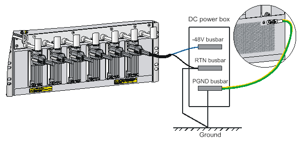
Grounding the router through the RTN wire of a DC power supply
|
|
CAUTION: Make sure the RTN wire is correctly grounded from the DC egress of the DC power cabinet. |
If the router is powered by a –48 V DC power supply and no grounding strip is available at the installation site, you can ground the router through the return (RTN) wire of the DC power supply, as shown in Figure 12.
Figure 12 Grounding the router through the RTN wire of the DC power supply