- Table of Contents
-
- 07-Security Configuration Guide
- 00-Preface
- 01-Security Overview
- 02-AAA Configuration
- 03-802.1X Configuration
- 04-MAC Authentication Configuration
- 05-Portal Configuration
- 06-Port Security Configuration
- 07-User Profile Configuration
- 08-Password Control Configuration
- 09-Public Key Configuration
- 10-PKI Configuration
- 11-SSH Configuration
- 12-SSL Configuration
- 13-SSL VPN Configuration
- 14-TCP Attack Protection Configuration
- 15-ARP Attack Protection Configuration
- 16-IPsec Configuration
- 17-ALG Configuration
- 18-Firewall Configuration
- 19-Session Management Configuration
- 20-Web Filtering Configuration
- 21-User Isolation Configuration
- 22-Source IP Address Verification Configuration
- 23-FIPS Configuration
- 24-Protocol Packet Rate Limit Configuration
- 25-Attack detection and protection configuration
- Related Documents
-
| Title | Size | Download |
|---|---|---|
| 16-IPsec Configuration | 349.12 KB |
Configuring an IPsec transform set
Applying an IPsec policy group to an interface
Configuring the IPsec anti-replay function
Configuring IPsec stateful failover
Displaying and maintaining IPsec
Configuration example for IPsec between AC and AP
IPsec stateful failover for LWAPP protection configuration example
Configuring an IKE-based IPsec tunnel for IPv4 packets (WX2540E/WAC360/WAC361)
Relationship between IKE and IPsec
Configuration task list for IKE
Configuring a name for the local security gateway
Setting the NAT keepalive timer
Disabling next payload field checking
Displaying and maintaining IKE
Failing to establish an IPsec tunnel
Configuring IPsec
The term "router" in this document refers to both routers and routing-capable H3C access controllers.
Only the WAC360 series, WX2540E, and the WX3000E series support IPsec between ACs. All ACs support IPsec between ACs and APs.
Overview
IP Security (IPsec) is a security framework defined by the IETF for securing IP communications. It transmits data in a secure tunnel established between two endpoints.
IPsec provides the following security services in insecure network environments:
· Confidentiality—The sender encrypts packets before transmitting them over the Internet. This protects the packets from being eavesdropped en route.
· Data integrity—The receiver verifies the packets received from the sender to make sure they are not tampered with during transmission.
· Data origin authentication—The receiver verifies the authenticity of the sender.
· Anti-replay—The receiver examines packets and drops outdated and duplicate packets.
IPsec delivers the following benefits:
· Reduced key negotiation overheads and simplified maintenance by supporting the IKE protocol. IKE provides automatic key negotiation and automatic IPsec security association (SA) setup and maintenance.
· Good compatibility. You can apply IPsec to all IP-based application systems and services without modifying them.
· Encryption on a per-packet rather than per-flow basis. Per-packet encryption allows for flexibility and greatly enhances IP security.
IPsec includes a set of protocols, including Authentication Header (AH), Encapsulating Security Payload (ESP), Internet Key Exchange (IKE), and algorithms for authentication and encryption. AH and ESP provides security services and IKE performs automatic key exchange. For more information about IKE, see Configuring IKE.
Basic concepts
Security protocols
IPsec comes with two security protocols:
· AH (protocol 51)—Provides data origin authentication, data integrity, and anti-replay services by adding an AH header to each IP packet. AH is suitable only for transmitting non-critical data because it cannot prevent eavesdropping, although it can prevent data tampering. AH supports authentication algorithms such as MD5 and SHA-1.
· ESP (protocol 50)—Provides data encryption as well as data origin authentication, data integrity, and anti-replay services by inserting an ESP header and an ESP trailer in IP packets. Unlike AH, ESP encrypts data before encapsulating the data to guarantee data confidentiality. ESP supports encryption algorithms such as DES, 3DES, and AES, and authentication algorithms such as MD5 and SHA-1. The authentication function is optional to ESP.
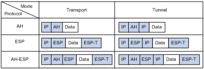
Both AH and ESP provide authentication services, but the authentication service provided by AH is stronger. In practice, you can choose either or both security protocols. When both AH and ESP are used, an IP packet is encapsulated first by ESP, and then by AH. Figure 1 shows the format of IPsec packets.
Security association
A security association is an agreement negotiated between two communicating parties called IPsec peers. It includes a set of parameters for data protection, including security protocols, encapsulation mode, authentication and encryption algorithms, and shared keys and their lifetime. SAs can be set up manually or through IKE.
An SA is unidirectional. At least two SAs are needed to protect data flows in a bidirectional communication. If two peers want to use both AH and ESP to protect data flows between them, they construct an independent SA for each protocol.
An SA is identified by a triplet, which consists of the security parameter index (SPI), destination IP address, and security protocol identifier (AH or ESP).
An SPI is a 32-bit number for uniquely identifying an SA. It is transmitted in the AH/ESP header. A manually configured SA requires an SPI to be specified manually for it. An IKE-created SA will have an SPI generated at random.
A manually configured SA never ages out. An IKE created SA has a specific period of lifetime, which comes in two types:
· Time-based lifetime—Defines how long the SA can be valid after it is created.
· Traffic-based lifetime—Defines the maximum traffic that the SA can process.
The SA becomes invalid when either of the lifetime timers expires. Before the SA expires, IKE negotiates a new SA, which takes over immediately after its creation.
Encapsulation modes
IPsec supports the following IP packet encapsulation modes:
· Tunnel mode—IPsec protects the entire IP packet, including both the IP header and the payload. It uses the entire IP packet to calculate an AH or ESP header, and then encapsulates the original IP packet and the AH or ESP header with a new IP header. If you use ESP, an ESP trailer is also encapsulated. Typically, tunnel mode is used for protecting gateway-to-gateway communications.
· Transport mode—IPsec protects only the IP payload. It uses only the IP payload to calculate the AH or ESP header, and inserts the calculated header between the original IP header and payload. If you use ESP, an ESP trailer is also encapsulated. Typically, the transport mode is used for protecting host-to-host or host-to-gateway communications.
|
|
NOTE: IPsec between an AC and an AP supports only the tunnel mode. |
Figure 1 shows how the security protocols encapsulate an IP packet in different encapsulation modes.
Figure 1 Encapsulation by security protocols in different modes
Authentication algorithms and encryption algorithms
· Authentication algorithms:
IPsec uses hash algorithms to perform authentication. A hash algorithm produces a fixed-length digest for an arbitrary-length message. IPsec peers calculate message digests for each packet. If the resulting digests are identical, the packet is considered intact.
IPsec supports the following hash algorithms for authentication:
¡ MD5—Takes a message of arbitrary length as input and produces a 128-bit message digest.
¡ SHA-1—Takes a message of a maximum length less than the 64th power of 2 in bits as input and produces a 160-bit message digest.
Compared with SHA-1, MD5 is faster but less secure.
· Encryption algorithms:
IPsec mainly uses symmetric encryption algorithms, which encrypt and decrypt data by using the same keys. The following encryption algorithms are available for IPsec on the device:
¡ DES—Encrypts a 64-bit plain text block with a 56-bit key. DES is the least secure but the fastest algorithm. It is sufficient for general security requirements.
¡ 3DES—Encrypts plain text data with three 56-bit DES keys. The key length totals up to 168 bits. It provides moderate security strength and is slower than DES.
¡ AES—Encrypts plain text data with a 128-bit, 192-bit, or 256-bit key. AES provides the highest security strength and is slower than 3DES.
IPsec SA setup modes
There are two IPsec SA setup modes:
· Manual mode—In this mode, you manually configure and maintain all SA settings. Advanced features like periodical key update are not available. However, this mode implements IPsec independently of IKE.
· ISAKMP mode—In this mode, IKE automatically negotiates and maintains IPsec SAs for IPsec.
IPsec tunnel
An IPsec tunnel is a bidirectional channel created between two peers. An IPsec tunnel includes one or more pairs of SAs.
IPsec stateful failover
Support for this feature depends on the device model. For more information, see About the H3C Access Controllers Configuration Guides.
The IPsec stateful failover function enables hot backup of IPsec service data between two devices. It is usually deployed on two redundant gateways at the headquarters to improve the availability of IPsec service.
The IPsec stateful failover function must work with the stateful failover feature and the VRRP feature.
The two devices in IPsec stateful failover must join the same VRRP group to act as a single virtual device. They use the virtual IP address of the virtual device to communicate with remote devices.
The IPsec stateful failover function can operate only in standard VRRP mode. In this mode, the master processes and forwards IPsec traffic, and the backup device only synchronizes IPsec service data with the master. When the master fails, the backup immediately takes over to forward IPsec traffic. This switchover process is transparent to remote devices. No extra configuration is required on remote devices, and no IPsec re-negotiation is required after the switchover.
Figure 2 IPsec stateful failover
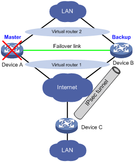
As shown in Figure 2, Device A and Device B form an IPsec stateful failover system and Device A is elected the master in the VRRP group. When Device A works correctly, it establishes an IPsec tunnel to Device C, and synchronizes its IPsec service data to Device B. The synchronized IPsec service data includes the IKE SA, IPsec SAs, anti-replay sequence number and window, SA lifetime in bytes, and DPD packet sequence number. Based on the IPsec service data, Device B creates standby IKE SA and standby IPsec SAs to back up the active IKE SA and active IPsec SAs on Device A. When Device A fails, the VRRP mechanism switches IPsec traffic from Device A to Device B. Because Device B has an instant copy of Device A's IPsec service data, Device B can process IPsec traffic immediately to provide nonstop IPsec service.
Protocols and standards
· RFC 2401, Security Architecture for the Internet Protocol
· RFC 2402, IP Authentication Header
· RFC 2406, IP Encapsulating Security Payload
· RFC 4301, Security Architecture for the Internet Protocol
· RFC 4302, IP Authentication Header
· RFC 4303, IP Encapsulating Security Payload (ESP)
Implementing ACL-based IPsec
The following is the generic configuration procedure for implementing ACL-based IPsec:
1. Configure an ACL for identifying data flows to be protected.
2. Configure IPsec transform sets to specify the security protocols, and authentication and encryption algorithms.
3. Configure an IPsec policy group to associate data flows with the IPsec transform sets and specify the SA negotiation mode, the peer IP addresses (the start and end points of the IPsec path), the required keys, and the SA lifetime.
4. Apply the IPsec policies to interfaces to finish IPsec configuration.
Complete the following tasks to configure ACL-based IPsec:
|
Task |
Remarks |
|
Required. |
|
|
Optional |
|
Typically, IKE uses UDP port 500 for communication, and AH and ESP use the protocol numbers 51 and 50. Make sure that flows of these protocols are not denied on the interfaces with IKE or IPsec configured.
Configuring an ACL
ACLs can be used to identify traffic. They are widely used in scenarios where traffic identification is desired, such as QoS and IPsec.
Keywords in ACL rules
IPsec uses ACLs to identify data flows. An ACL is a collection of ACL rules. Each ACL rule is a deny or permit statement. A permit statement identifies a data flow protected by IPsec, and a deny statement identifies a data flow that is not protected by IPsec. With IPsec, a packet is matched against the referenced ACL rules and processed according to the first rule that it matches:
· Each ACL rule matches both the outbound traffic and the returned inbound traffic. Suppose there is a rule rule 0 permit ip source 1.1.1.0 0.0.0.255 destination 2.2.2.0 0.0.0.255. This rule matches both traffic from 1.1.1.0 to 2.2.2.0 and traffic from 2.2.2.0 to 1.1.1.0.
· In the outbound direction, if a permit statement is matched, IPsec considers that the packet requires protection and continues to process it. If a deny statement is matched or no match is found, IPsec considers that the packet does not require protection, and it delivers the packet to the next function module.
· In the inbound direction:
¡ Non-IPsec packets that match a permit statement are dropped.
¡ IPsec packets destined for the device itself are de-encapsulated. The de-encapsulated packets are compared against the ACL rules. Only those that match a permit statement are processed by other modules. Other packets are dropped.
When defining ACL rules for IPsec, follow these guidelines:
· Permit only data flows that need to be protected and use the any keyword with caution. With the any keyword specified in a permit statement, all outbound traffic matching the permit statement is protected by IPsec and all inbound IPsec packets matching the permit statement is received and processed. However, all inbound non-IPsec packets are dropped. This causes all the inbound traffic that does not need IPsec protection to be dropped.
· Avoid statement conflicts in the scope of IPsec policy groups. When creating a deny statement, be careful with its matching scope and matching order relative to permit statements. The policies in an IPsec policy group have different match priorities. ACL rule conflicts between them are prone to cause mistreatment of packets. For example, when configuring a permit statement for an IPsec policy to protect an outbound traffic flow, you must avoid the situation that the traffic flow matches a deny statement in a higher priority IPsec policy. Otherwise, the packets are sent out as normal packets. If they match a permit statement at the receiving end, they are dropped by IPsec.
The following configuration example shows how an improper statement causes unexpected packet dropping. Only the ACL-related configurations are presented.
Router A connects the segment 1.1.2.0/24 and Router B connects the segment 3.3.3.0/24. On Router A, apply the IPsec policy group test to the outbound interface of Router A. The IPsec policy group contains two policies, test 1 and test 2. The ACLs referenced by the two policies each contain a rule that matches traffic from 1.1.2.0/24 to 3.3.3.0/24. The one referenced in policy test 1 is a deny statement and the one referenced in policy test 2 is a permit statement. Because test 1 is matched before test 2, traffic from 1.1.2.0/24 to 3.3.3.0/24 matches the deny statement and is sent as normal traffic. When the traffic arrives at Router B, it is dropped if it matches a permit statement in the ACL referenced in the applied IPsec policy.
· Configure Router A:
acl number 3000
rule 0 permit ip source 1.1.1.0 0.0.0.255 destination 2.2.2.0 0.0.0.255
rule 1 deny ip
acl number 3001
rule 0 permit ip source 1.1.2.0 0.0.0.255 destination 3.3.3.0 0.0.0.255
rule 1 deny ip
#
ipsec policy test 1 isakmp
security acl 3000
ike-peer aa
transform-set 1
#
ipsec policy test 2 isakmp
security acl 3001
ike-peer bb
transform-set 1
· Configure Router B:
acl number 3001
rule 0 permit ip source 3.3.3.0 0.0.0.255 destination 1.1.2.0 0.0.0.255
rule 1 deny ip
#
ipsec policy test 1 isakmp
security acl 3001
ike-peer aa
transform-set 1
Mirror image ACLs
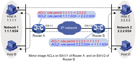
To make sure that SAs can be set up and the traffic protected by IPsec can be processed correctly at the remote peer, on the remote peer, create a mirror image ACL rule for each ACL rule created at the local peer. As shown in Figure 3, ACL rules on Router B are mirror images of the rules on Router A. This makes sure that SAs can be created successfully for the traffic between Host A and Host C and the traffic between Network 1 and Network 2.
If the ACL rules on peers do not form mirror images of each other, SAs can be set up only when both of the following requirements are met:
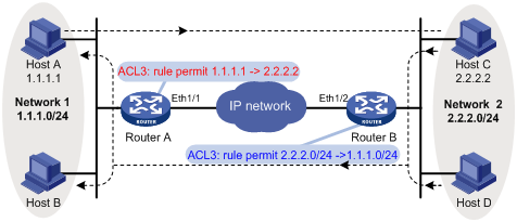
· The range specified by an ACL rule on one peer is covered by its counterpart ACL rule on the other peer. As shown in Figure 4, the range specified by the ACL rule configured on Router A is covered by its counterpart on Router B.
· The peer with the narrower rule initiates SA negotiation. If a wider ACL rule is used by the SA initiator, the negotiation request might be rejected because the matching traffic is beyond the scope of the responder. As shown in Figure 4, the SA negotiation initiated by Host A to Host C is accepted, but the SA negotiations from Host C to Host B or from Host D to Host A is rejected.
Figure 4 Non-mirror image ACLs
Protection modes
Data flows can be protected in the following modes:
· Standard mode—One tunnel protects one data flow. The data flow permitted by an ACL rule is protected by one tunnel that is established solely for it.
· Aggregation mode—One tunnel protects all data flows permitted by all the rules of an ACL. This mode is configurable only in IPsec policies that use IKE negotiation.
· Per-host mode—One tunnel protects one host-to-host data flow. One host-to-host data flow is identified by one ACL rule and protected by one tunnel established solely for it. This mode is configurable only in IPsec policies that use IKE negotiation.
For more information about ACL configuration, see ACL and QoS Configuration Guide.
To use IPsec in combination with QoS, make sure that IPsec's ACL classification rules match the QoS classification rules. If the rules do not match, QoS might classify the packets of one IPsec SA to different queues, causing packets to be sent out of order. When the anti-replay function is enabled, IPsec discards the packets beyond the anti-replay window in the inbound direction, resulting in packet loss. For more information about QoS classification rules, see ACL and QoS Configuration Guide.
Configuring an IPsec transform set
An IPsec transform set, part of an IPsec policy, defines the security parameters for IPsec SA negotiation, including the security protocol, and the encryption and authentication algorithms.
You can configure up to 10000 IPsec transform sets in the system.
To configure an IPsec transform set:
|
Step |
Command |
Remarks |
|
1. Enter system view. |
system-view |
N/A |
|
2. Create an IPsec transform set and enter its view. |
ipsec transform-set transform-set-name |
By default, no IPsec transform set exists. |
|
3. Specify the security protocol for the IPsec transform set. |
transform { ah | ah-esp | esp } |
Optional. ESP by default. |
|
4. Specify the security algorithms. |
· Specify the encryption algorithm for ESP: · Specify the authentication algorithm for ESP: · Specify the authentication algorithm for AH: |
Configure at least one command. You configure security algorithms for a security protocol only after you specify the security protocol in the IPsec transform set. For example, you can specify the ESP-specific security algorithms only when you select ESP as the security protocol. ESP supports three IP packet protection schemes: encryption only, authentication only, or both encryption and authentication. In FIPS mode: · ESP does not support DES, 3DES, or MD5. It uses AES-128 for encryption and SHA-1 for authentication by default. · AH does not support MD5 authentication, and it uses SHA-1 for authentication. · You must specify both an encryption algorithm and an authentication algorithm. In non-FIPS mode: · ESP uses DES for encryption and MD5 for authentication by default. · AH uses MD5 for authentication by default. |
|
5. Specify the IP packet encapsulation mode for the IPsec transform set. |
encapsulation-mode { transport | tunnel } |
Optional. Tunnel mode by default. Transport mode applies only when the source and destination IP addresses of data flows match those of the IPsec tunnel. |
Changes to an IPsec transform set affect only SAs negotiated after the changes. To apply the changes to existing SAs, execute the reset ipsec sa command to clear the SAs so that they can be set up using the updated parameters.
Configuring an IPsec policy
IPsec policies define which IPsec transform sets should be used to protect which data flows. An IPsec policy is uniquely identified by its name and sequence number.
To configure an IPsec policy that uses IKE, use one of the following methods:
· Directly configure it by configuring the parameters in IPsec policy view.
· Configure it by referencing an existing IPsec policy template with the parameters to be negotiated configured. A device referencing an IPsec policy that is configured in this way cannot initiate SA negotiation, but it can respond to a negotiation request. The parameters not defined in the template are determined by the initiator. This method applies to scenarios where the remote end's information, such as the IP address, is unknown.
Before you configure an IPsec policy that uses IKE, complete the following tasks:
· Configure the ACLs and the IPsec transform sets for the IPsec policy.
· Configure the IKE peer. For more information about IKE peer configuration, see Configuring IKE.
The parameters for the local and remote ends must match.
Directly configuring an IPsec policy that uses IKE
|
Step |
Command |
Remark |
|
1. Enter system view. |
system-view |
N/A |
|
2. Create an IPsec policy that uses IKE and enter its view. |
ipsec policy policy-name seq-number isakmp |
By default, no IPsec policy exists. |
|
3. Configure an IPsec connection name. |
connection-name name |
Optional. By default, no IPsec connection name is configured. |
|
4. Assign an ACL to the IPsec policy. |
security acl acl-number [ aggregation | per-host ] |
By default, an IPsec policy references no ACL. |
|
5. Assign IPsec transform sets to the IPsec policy. |
transform-set transform-set-name&<1-6> |
By default, an IPsec policy references no IPsec transform set. |
|
6. Specify an IKE peer for the IPsec policy. |
ike-peer peer-name |
N/A |
|
7. Set the SA lifetime. |
sa duration { time-based seconds | traffic-based kilobytes } |
Optional. By default, the global SA lifetime is used. |
|
8. Set the anti-replay information synchronization intervals in IPsec stateful failover mode. |
synchronization anti-replay-interval inbound inbound-number outbound outbound-number |
Optional. By default, the inbound anti-replay window information is synchronized whenever 1000 packets are received, and the outbound anti-replay sequence number is synchronized whenever 100000 packets are sent. Support for this feature depends on the device model. For more information, see About the H3C Access Controllers Configuration Guides. |
|
9. Enable the IPsec policy. |
policy enable |
Optional. Enabled by default. |
|
10. Return to system view. |
quit |
N/A |
|
11. Set the global SA lifetime. |
ipsec sa global-duration { time-based seconds | traffic-based kilobytes } |
Optional. 3600 seconds for time-based SA lifetime by default. 1843200 kilobytes for traffic-based SA lifetime by default. |
Configuring an IPsec policy that uses IKE by referencing an IPsec policy template
The parameters configurable for an IPsec policy template are the same as those you configure when directly configuring an IPsec policy that uses IKE.
· Required configuration: The IPsec transform sets and IKE peer.
· Optional configuration: The ACL. Unlike the direct configuration, ACL configuration to be referenced by an IPsec policy is optional. The responder without ACL configuration accepts the initiator's ACL configuration.
To configure an IPsec policy that uses IKE by referencing an IPsec policy template:
|
Step |
Command |
Remark |
|
1. Enter system view. |
system-view |
N/A |
|
2. Create an IPsec policy template and enter its view. |
ipsec policy-template template-name seq-number |
By default, no IPsec policy template exists. |
|
3. Specify the ACL for the IPsec policy to reference. |
security acl acl-number |
Optional. By default, an IPsec policy references no ACL. |
|
4. Specify the IPsec transform sets for the IPsec policy to reference. |
transform-set transform-set-name&<1-6> |
By default, an IPsec policy references no IPsec transform set. |
|
5. Specify the IKE peer for the IPsec policy to reference. |
ike-peer peer-name |
N/A |
|
6. Configure the SA lifetime. |
sa duration { time-based seconds | traffic-based kilobytes } |
Optional. By default, the global SA lifetime settings are used. |
|
7. Set the anti-replay information synchronization intervals in IPsec stateful failover mode. |
synchronization anti-replay-interval inbound inbound-number outbound outbound-number |
Optional. By default, the inbound anti-replay window information is synchronized whenever 1000 packets are received, and the outbound anti-replay sequence number is synchronized whenever 100000 packets are sent. Support for this feature depends on the device model. For more information, see About the H3C Access Controllers Configuration Guides. |
|
8. Enable the IPsec policy. |
policy enable |
Optional. Enabled by default. |
|
9. Return to system view. |
quit |
N/A |
|
10. Configure the global SA lifetime. |
ipsec sa global-duration { time-based seconds | traffic-based kilobytes } |
Optional. By default, time-based SA lifetime is 3600 seconds and traffic-based SA lifetime is 1843200 kilobytes. |
|
11. Create an IPsec policy by referencing an IPsec policy template. |
ipsec policy policy-name seq-number isakmp template template-name |
By default, no IPsec policy exists. |
An IPsec policy can reference only one ACL. If you specify an ACL for an IPsec policy multiple times, the most recent configuration takes effect.
With SAs to be established through IKE negotiation, an IPsec policy can reference up to six IPsec transform sets. During negotiation, IKE searches for a fully matched IPsec transform set at the two ends of the expected IPsec tunnel. If no match is found, no SA can be set up and the packets expecting to be protected are dropped.
An SA uses the global lifetime settings when it is not configured with lifetime settings in IPsec policy view. When negotiating to set up SAs, IKE uses the local lifetime settings or those proposed by the peer, whichever are smaller.
You can set both the time-based SA lifetime and the traffic-based SA lifetime. Once the time-based lifetime or traffic-based lifetime of an SA elapses, the SA is aged.
You cannot modify an IPsec policy created by referencing an IPsec policy template in IPsec policy view. You can perform the modifications in IPsec policy template view.
You cannot directly modify the creation mode (direct creation or template-based creation) of an IPsec policy. To do so, delete the IPsec policy, and then re-create the IPsec policy in the desired mode.
Applying an IPsec policy group to an interface
An IPsec policy group is a collection of IPsec policies with the same name but different sequence numbers. In an IPsec policy group, an IPsec policy with a smaller sequence number has a higher priority.
You can apply an IPsec policy group to an interface to protect certain data flows. To cancel the IPsec protection, remove the application of the IPsec policy group.
For each packet to be sent out an IPsec protected interface, the system looks through the IPsec policies in the IPsec policy group in ascending order of sequence numbers. If an IPsec policy matches the packet, the system uses the IPsec policy to protect the packet. If no match is found, the system sends the packet out without IPsec protection.
An interface can reference only one IPsec policy group. An IKE-based IPsec policy can be applied to more than one interface. A manually created IPsec policy can be applied to only one interface.
To apply an IPsec policy group to an interface:
|
Step |
Command |
|
1. Enter system view. |
system-view |
|
2. Enter interface view. |
interface interface-type interface-number |
|
3. Apply an IPsec policy group to the interface. |
ipsec policy policy-name |
Configuring the IPsec anti-replay function
The IPsec anti-replay function protects networks against anti-replay attacks by using a sliding window mechanism called anti-replay window. This function checks the sequence number of each received IPsec packet against the current IPsec packet sequence number range of the sliding window. If the sequence number is not in the current sequence number range, the packet is considered a replayed packet and is discarded.
IPsec packet de-encapsulation involves complicated calculation. De-encapsulation of replayed packets not only makes no sense, but also consumes large amounts of resources and degrades performance, resulting in DoS. IPsec anti-replay checking, when enabled, is performed before the de-encapsulation process, reducing resource waste.
In some cases, however, the sequence numbers of some normal service data packets might be out of the current sequence number range, and the IPsec anti-replay function might drop them as well, affecting the normal communications. If this happens, disable IPsec anti-replay checking or adjust the size of the anti-replay window as required.
IPsec anti-replay checking does not affect manually created IPsec SAs. According to the IPsec protocol, only IPsec SAs negotiated by IKE support anti-replay checking.
|
|
IMPORTANT: · IPsec anti-replay checking is enabled by default. Do not disable it unless it needs to be disabled. · A wider anti-replay window results in higher resource cost and more system performance degradation, which is against the original intention of the IPsec anti-replay function. Specify an anti-replay window size that is as small as possible. |
To configure IPsec anti-replay checking:
|
Step |
Command |
Remarks |
|
1. Enter system view. |
system-view |
N/A |
|
2. Enable IPsec anti-replay checking. |
ipsec anti-replay check |
Optional. Enabled by default. |
|
3. Set the size of the IPsec anti-replay window. |
ipsec anti-replay window width |
Optional. 32 by default. |
Enabling invalid SPI recovery
When the security gateway at one end of an IPsec tunnel loses its SAs due to rebooting or any other reason, its peer security gateway might not know the problem and sends IPsec packets to it. These packets will be discarded by the receiver because the receiver cannot find appropriate SAs for them, resulting in a traffic blackhole. The problem persists till the old SAs on the sender are aged out and new SAs are established between the two peers. To prevent such service interruption, configure the invalid SPI recovery feature.
The invalid SPI recovery feature allows the receiver to send an INVALID SPI NOTIFY message to tell the sender the invalid SPIs. Upon receiving the message, the sender immediately deletes the corresponding SAs. The subsequent traffic triggers the two peers to set up new SAs for data transmission.
Because attackers might exploit INVALID SPI NOTIFY messages to attack the IPsec packet sender (DoS attack), the invalid SPI recovery feature is disabled by default, making the receiver discard packets with invalid SPIs.
To enable invalid SPI recovery:
|
Step |
Command |
Remarks |
|
1. Enter system view. |
system-view |
N/A |
|
2. Enable invalid SPI recovery. |
ipsec invalid-spi-recovery enable |
Optional. Disabled by default. |
Configuring IPsec stateful failover
In an IPsec stateful failover scenario, these restrictions apply:
· VRRP must operate in the standard protocol mode.
· IPsec stateful failover supports only the active/standby failover mode.
· RSA signature authentication is not supported in IKE negotiation.
· The keepalive mechanism for IKE to maintain the link status of IKE SAs is not supported.
Support for this feature depends on the device model. For more information, see About the H3C Access Controllers Configuration Guides.
Configuration prerequisites
Before you configure IPsec stateful failover, complete the tasks in this section on the two devices.
1. Configure stateful failover.
¡ Configure the devices to operate in the active/standby mode.
¡ Specify the interfaces between the devices as failover interfaces for transferring state negotiation messages and backing up IPsec service data.
For more information about stateful failover, see High Availability Configuration Guide.
2. Configure VRRP.
¡ On each device, configure a VRRP group for the uplink interface and a VRRP group for the downlink interface, and assign virtual IP addresses to the groups.
¡ Set the priorities of the devices in the groups, making sure that one of the devices is the master in both VRRP groups.
¡ Configure the devices to operate in the same mode (preemption mode or non-preemptive mode) in both VRRP groups. To deploy the preemption mode, set the preemption delay of the backup device to 0 so the backup device can immediately take over when the priority of the master comes down, and set the preemption delay of the backup to a bigger value such as 255 seconds so the master has enough time to synchronize IPsec service data with the backup device after it recovers.
For more information about VRRP, see High Availability Configuration Guide.
3. Configure IPsec and IKE.
¡ Create and configure the same IKE peers on the two devices. The local gateway addresses of the IKE peers must be the virtual IP address of the uplink VRRP group.
¡ Create and configure the same IPsec policies or IPsec profiles that use IKE on the two devices.
¡ Apply the IPsec policies or IPsec profiles to the uplink interfaces on the two devices. If you change the virtual IP address after applying the IPsec policy to an interface, be sure to re-apply the IPsec policy to the interface.
Configuration procedure
To implement IPsec stateful failover on two devices, you must enable IPsec stateful failover on both devices.
To configure IPsec stateful failover on a device:
|
Step |
Command |
Remarks |
|
1. Enter system view. |
system-view |
N/A |
|
2. Enable IPsec stateful failover. |
ipsec synchronization enable |
By default, IPsec stateful failover is enabled. |
Displaying and maintaining IPsec
|
Task |
Command |
Remarks |
|
Display IPsec policy information. |
display ipsec policy [ brief | name policy-name [ seq-number ] ] [ | { begin | exclude | include } regular-expression ] |
Available in any view. |
|
Display IPsec policy template information. |
display ipsec policy-template [ brief | name template-name [ seq-number ] ] [ | { begin | exclude | include } regular-expression ] |
Available in any view. |
|
Display IPsec transform set information. |
display ipsec transform-set [ transform-set-name ] [ | { begin | exclude | include } regular-expression ] |
Available in any view. |
|
Display IPsec SA information. |
display ipsec sa [ active | brief | policy policy-name [ seq-number ] | remote ip-address | standby ] [ | { begin | exclude | include } regular-expression ] |
Available in any view. Support for the active and standby keywords depends on the device model. For more information, see About the H3C Access Controllers Command References. |
|
Display IPsec packet statistics. |
display ipsec statistics [ tunnel-id integer ] [ | { begin | exclude | include } regular-expression ] |
Available in any view. |
|
Display IPsec tunnel information. |
display ipsec tunnel [ active | standby ] [ | { begin | exclude | include } regular-expression ] |
Available in any view. Support for the active and standby keywords depends on the device model. For more information, see About the H3C Access Controllers Command References. |
|
Clear SAs. |
reset ipsec sa [ active | parameters dest-address protocol spi | policy policy-name [ seq-number ] | remote ip-address | standby ] |
Available in user view. Support for the active and standby keywords depends on the device model. For more information, see About the H3C Access Controllers Command References. |
|
Clear IPsec statistics. |
reset ipsec statistics |
Available in user view. |
IPsec configuration examples
Configuration example for IPsec between AC and AP
For more information, see WLAN Configuration Guide.
IPsec stateful failover for LWAPP protection configuration example
Network requirements
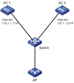
A company uses ACs and APs to construct its internal network. IPsec and reliability are required between ACs and APs.
Configure the ACs as follows:
· Assign the ACs to the VLAN to which the AP belongs.
· Configure stateful failover between AC 1 and AC 2. The ACs send heartbeat packets to each other through the switch.
· Set up an IPsec tunnel between AC 1 and the AP and an IPsec tunnel between AC 2 and the AP, and set up connections based on the IPsec tunnels.
Figure 5 Network diagram
Configuring AC 1
# Configure an IP address for VLAN-interface 1.
<AC1> system-view
[AC1] interface Vlan-interface 1
[AC1-Vlan-interface1] ip address 133.1.1.1 16
[AC1-Vlan-interface1] quit
# Enable stateful failover and set the stateful failover heartbeat interval.
[AC1] hot-backup enable
[AC1] hot-backup hellointerval 100
# Set the IKE SA keepalive interval.
[AC1] ike sa keepalive-timer interval 20
# Set the IKE SA keepalive timeout.
[AC1] ike sa keepalive-timer timeout 60
# Enable invalid SPI recovery.
[AC1] ipsec invalid-spi-recovery enable
# Create an IPsec transform set named tran1.
[AC1] ipsec transform-set tran1
# Configure the IPsec transform set to use security protocol ESP, authentication algorithm SHA-1, and encryption algorithm AES-CBC-128.
[AC1-ipsec-transform-set-tran1] esp authentication-algorithm sha1
[AC1-ipsec-transform-set-tran1] esp encryption-algorithm aes-cbc-128
[AC1-ipsec-transform-set-tran1] quit
# Create IKE proposal 1.
[AC1] ike proposal 1
# Specify encryption algorithm AES-CBC-128 and DH group 2 for IKE proposal 1.
[AC1-ike-proposal-1] encryption-algorithm aes-cbc 128
[AC1-ike-proposal-1] dh group2
[AC1-ike-proposal-1] quit
# Create a DPD named dpd.
[AC1] ike dpd dpd
[AC1-ike-dpd-dpd] quit
# Create an IKE peer named peer1.
[AC1] ike peer peer1
# Apply dpd to IKE peer peer1.
[AC1-ike-peer-peer1] dpd dpd
# Apply IKE proposal 1 to IKE peer peer1.
[AC1-ike-peer-peer1] proposal 1
# Configure a plaintext pre-shared key 123456 for IKE negotiation.
[AC1-ike-peer-peer1] pre-shared-key simple 123456
# Specify the IP address of the remote IKE peer as 133.1.1.33.
[AC1-ike-peer-peer1] remote-address 133.1.1.33
[AC1-ike-peer-peer1] quit
# Create an IPsec policy template named pt with the sequence number 1.
[AC1] ipsec policy-template pt 1
# Reference the IPsec transform set tran1 for the IPsec policy template.
[AC1-ipsec-policy-template-pt-1] transform-set tran1
# Specify the IKE peer peer1 for the IPsec policy template.
[AC1-ipsec-policy-template-pt-1] ike-peer peer1
[AC1-ipsec-policy-template-pt-1] quit
# Create an IPsec policy named map with the sequence number 1 by referencing IPsec policy template pt.
[AC1] ipsec policy map 1 isakmp template pt
# Apply the IPsec policy to VLAN-interface 1.
[AC1] interface vlan-interface 1
[AC1-Vlan-interface1] ipsec policy map
[AC1-Vlan-interface1] quit
# Create an AP template named ap, specify the AP model and AP serial number, specify the IP address of the backup AC, and configure the connection priority for the AP.
[AC1] wlan ap ap model MSM460-WW
[AC1-wlan-ap-ap] serial-id CN2AD330S8
[AC1-wlan-ap-ap] backup-ac ip 133.1.1.2
[AC1-wlan-ap-ap] priority level 7
# Create and enter the provision view for the AP.
[AC1-wlan-ap-ap] provision
# Configure the IPsec pre-shared key as plaintext 123456 for the AP.
[AC1-wlan-ap-ap-prvs] tunnel encryption ipsec pre-shared-key simple 123456
# Enable IPsec encryption for the AP data tunnel.
[AC1-wlan-ap-ap-prvs] data-tunnel encryption enable
# After the AP comes online, save the AP configuration to the AP's configuration file.
[AC1-wlan-ap-ap-prvs] save wlan ap provision name ap
[AC1-wlan-ap-ap-prvs] quit
[AC1-wlan-ap-ap] quit
[AC1] quit
# Reboot the AP.
<AC1> reset wlan ap name ap
This command will reset all master connection AP's.
Do you want to continue [Y/N]:y
Configuring AC 2
# Configure an IP address for VLAN-interface 1.
<AC2> system-view
[AC2] interface vlan-interface 1
[AC2-Vlan-interface1] ip address 133.1.1.2 16
[AC2-Vlan-interface1] quit
# Enable stateful failover and set the stateful failover heartbeat interval.
[AC2] hot-backup enable
[AC2] hot-backup hellointerval 100
# Set the IKE SA keepalive interval.
[AC2] ike sa keepalive-timer interval 20
# Set the IKE SA keepalive timeout.
[AC2] ike sa keepalive-timer timeout 60
# Enable invalid SPI recovery.
[AC2] ipsec invalid-spi-recovery enable
# Create an IPsec transform set named tran1.
[AC2] ipsec transform-set tran1
# Configure the IPsec transform set to use security protocol ESP, authentication algorithm SHA-1, and encryption algorithm AES-CBC-128.
[AC2-ipsec-transform-set-tran1] esp authentication-algorithm sha1
[AC2-ipsec-transform-set-tran1] esp encryption-algorithm aes-cbc-128
[AC2-ipsec-transform-set-tran1] quit
# Create IKE proposal 1.
[AC2] ike proposal 1
# Specify encryption algorithm AES-CBC-128 and DH group 2 for IKE proposal 1.
[AC2-ike-proposal-1] encryption-algorithm aes-cbc 128
[AC2-ike-proposal-1] dh group2
[AC2-ike-proposal-1] quit
# Create a DPD named dpd.
[AC2] ike dpd dpd
[AC2-ike-dpd-dpd] quit
# Create an IKE peer named peer1.
[AC2] ike peer peer1
# Apply dpd to IKE peer peer1.
[AC2-ike-peer-peer1] dpd dpd
# Apply IKE proposal 1 to IKE peer peer1.
[AC1-ike-peer-peer1] proposal 1
# Configure a plaintext pre-shared key 123456 for IKE negotiation.
[AC2-ike-peer-peer1] pre-shared-key simple 123456
# Specify the IP address of the remote IKE peer as 133.1.1.33.
[AC2-ike-peer-peer1] remote-address 133.1.1.33
[AC2-ike-peer-peer1] quit
# Create an IPsec policy template named pt with the sequence number 1.
[AC2] ipsec policy-template pt 1
# Reference the IPsec transform set tran1 for the IPsec policy template.
[AC2-ipsec-policy-template-pt-1] transform-set tran1
# Specify the IKE peer peer1 for the IPsec policy template.
[AC2-ipsec-policy-template-pt-1] ike-peer peer1
[AC2-ipsec-policy-template-pt-1] quit
# Create an IPsec policy with named map with the sequence number 1 by referencing IPsec policy template pt.
[AC2] ipsec policy map 1 isakmp template pt
# Apply the IPsec policy to VLAN-interface 1.
[AC2] interface vlan-interface 1
[AC2-Vlan-interface1] ipsec policy map
[AC2-Vlan-interface1] quit
# Create an AP template named ap , specify the AP model and AP serial number, specify the IP address of the backup AC, and configure the connection priority for the AP.
[AC2] wlan ap ap model MSM460-WW
[AC2-wlan-ap-ap] serial-id CN2AD330S8
[AC2-wlan-ap-ap] backup-ac ip 133.1.1.1
[AC2-wlan-ap-ap] priority level 1
[AC2-wlan-ap-ap] quit
Verifying the configuration
# Execute the display wlan ap all command on each AC to display the AP information.
<AC1> display wlan ap all
Total Number of APs configured : 1
Total Number of configured APs connected : 1
Total Number of auto APs connected : 0
AP Profiles
State : I = Idle, J = Join, JA = JoinAck, IL = ImageLoad
C = Config, R = Run, KU = KeyUpdate, KC = KeyCfm
---------------------------------------------------------------------------
AP Name State Model Serial-ID
---------------------------------------------------------------------------
ap R/M MSM460-WW CN2AD330S8
---------------------------------------------------------------------------
<AC1>
<AC2>display wlan ap all
Total Number of APs configured : 1
Total Number of configured APs connected : 1
Total Number of auto APs connected : 0
AP Profiles
State : I = Idle, J = Join, JA = JoinAck, IL = ImageLoad
C = Config, R = Run, KU = KeyUpdate, KC = KeyCfm
---------------------------------------------------------------------------
AP Name State Model Serial-ID
---------------------------------------------------------------------------
ap R/B MSM460-WW CN2AD330S8
---------------------------------------------------------------------------
<AC2>
# Execute the display ipsec sa command on each AC to display information about IPsec SAs.
<AC1> display ipsec sa
===============================
Interface: Vlan-interface1
path MTU: 1500
===============================
-----------------------------
IPsec policy name: "pt"
sequence number: 1
mode: template
-----------------------------
connection id: 7
encapsulation mode: tunnel
perfect forward secrecy:
tunnel:
local address: 133.1.1.1
remote address: 133.1.1.33
flow:
sour addr: 133.1.1.1/255.255.255.255 port: 12223 protocol: UDP
dest addr: 133.1.1.33/255.255.255.255 port: 0 protocol: UDP
[inbound ESP SAs]
spi: 220165574 (0x0d1f75c6)
proposal: ESP-ENCRYPT-AES-128 ESP-AUTH-SHA1
sa duration (kilobytes/sec): 1843200/3600
sa remaining duration (kilobytes/sec): 1843177/3261
max received sequence-number: 126
anti-replay check enable: Y
anti-replay window size: 32
udp encapsulation used for nat traversal: N
status: --
[outbound ESP SAs]
spi: 620434955 (0x24fb160b)
proposal: ESP-ENCRYPT-AES-128 ESP-AUTH-SHA1
sa duration (kilobytes/sec): 1843200/3600
sa remaining duration (kilobytes/sec): 1843192/3261
max received sequence-number: 127
udp encapsulation used for nat traversal: N
status: --
-----------------------------
IPsec policy name: "pt"
sequence number: 1
mode: template
-----------------------------
connection id: 8
encapsulation mode: tunnel
perfect forward secrecy:
tunnel:
local address: 133.1.1.1
remote address: 133.1.1.33
flow:
sour addr: 133.1.1.1/255.255.255.255 port: 12222 protocol: UDP
dest addr: 133.1.1.33/255.255.255.255 port: 0 protocol: UDP
[inbound ESP SAs]
spi: 2106938486 (0x7d955476)
proposal: ESP-ENCRYPT-AES-128 ESP-AUTH-SHA1
sa duration (kilobytes/sec): 1843200/3600
sa remaining duration (kilobytes/sec): 1843194/3262
max received sequence-number: 111
anti-replay check enable: Y
anti-replay window size: 32
udp encapsulation used for nat traversal: N
status: --
[outbound ESP SAs]
spi: 1822532692 (0x6ca1a454)
proposal: ESP-ENCRYPT-AES-128 ESP-AUTH-SHA1
sa duration (kilobytes/sec): 1843200/3600
sa remaining duration (kilobytes/sec): 1843200/3262
max received sequence-number: 1
udp encapsulation used for nat traversal: N
status: --
<AC1>
<AC2> display ipsec sa
===============================
Interface: Vlan-interface1
path MTU: 1500
===============================
-----------------------------
IPsec policy name: "pt"
sequence number: 1
mode: template
-----------------------------
connection id: 6
encapsulation mode: tunnel
perfect forward secrecy:
tunnel:
local address: 133.1.1.2
remote address: 133.1.1.33
flow:
sour addr: 133.1.1.2/255.255.255.255 port: 12223 protocol: UDP
dest addr: 133.1.1.33/255.255.255.255 port: 0 protocol: UDP
[inbound ESP SAs]
spi: 1636801638 (0x618f9c66)
proposal: ESP-ENCRYPT-AES-128 ESP-AUTH-SHA1
sa duration (kilobytes/sec): 1843200/3600
sa remaining duration (kilobytes/sec): 1843159/2980
max received sequence-number: 206
anti-replay check enable: Y
anti-replay window size: 32
udp encapsulation used for nat traversal: N
status: --
[outbound ESP SAs]
spi: 1048421470 (0x3e7da45e)
proposal: ESP-ENCRYPT-AES-128 ESP-AUTH-SHA1
sa duration (kilobytes/sec): 1843200/3600
sa remaining duration (kilobytes/sec): 1843189/2980
max received sequence-number: 207
udp encapsulation used for nat traversal: N
status: --
-----------------------------
IPsec policy name: "pt"
sequence number: 1
mode: template
-----------------------------
connection id: 7
encapsulation mode: tunnel
perfect forward secrecy:
tunnel:
local address: 133.1.1.2
remote address: 133.1.1.33
flow:
sour addr: 133.1.1.2/255.255.255.255 port: 12222 protocol: UDP
dest addr: 133.1.1.33/255.255.255.255 port: 0 protocol: UDP
[inbound ESP SAs]
spi: 1751951131 (0x686ca71b)
proposal: ESP-ENCRYPT-AES-128 ESP-AUTH-SHA1
sa duration (kilobytes/sec): 1843200/3600
sa remaining duration (kilobytes/sec): 1843190/2981
max received sequence-number: 205
anti-replay check enable: Y
anti-replay window size: 32
udp encapsulation used for nat traversal: N
status: --
[outbound ESP SAs]
spi: 2945451878 (0xaf900766)
proposal: ESP-ENCRYPT-AES-128 ESP-AUTH-SHA1
sa duration (kilobytes/sec): 1843200/3600
sa remaining duration (kilobytes/sec): 1843200/2981
max received sequence-number: 1
udp encapsulation used for nat traversal: N
status: --
<AC2>
# Execute the display ike sa command to display information about IKE SAs.
<AC1> display ike sa
total phase-1 SAs: 1
connection-id peer flag phase doi status
-----------------------------------------------------------------------
60 133.1.1.33 RD 1 IPSEC --
61 133.1.1.33 RD 2 IPSEC --
62 133.1.1.33 RD 2 IPSEC --
flag meaning
RD--READY ST--STAYALIVE RL--REPLACED FD--FADING TO--TIMEOUT
<AC1>
<AC2> display ike sa
total phase-1 SAs: 1
connection-id peer flag phase doi status
-----------------------------------------------------------------------
117 133.1.1.33 RD 1 IPSEC --
120 133.1.1.33 RD 2 IPSEC --
121 133.1.1.33 RD 2 IPSEC --
flag meaning
RD--READY ST--STAYALIVE RL--REPLACED FD--FADING TO--TIMEOUT
<AC2>
After the IKE negotiation succeeds and IPsec SAs are successfully established, LWAPP tunneled packets between the AP and the ACs are encrypted by IPsec.
Configuring an IKE-based IPsec tunnel for IPv4 packets (WX2540E/WAC360/WAC361)
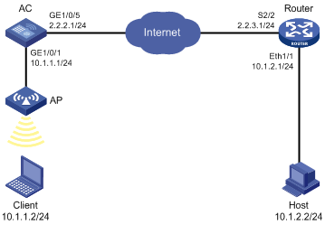
Network requirements
As shown in Figure 6, establish an IPsec tunnel between the AC and the router to protect data flows between subnet 10.1.1.0/24 and subnet 10.1.2.0/24.
Configure the IPsec tunnel as follows:
· Specify the encapsulation mode as tunnel, the security protocol as ESP, the encryption algorithm as DES, and the authentication algorithm as SHA1-HMAC-96.
· Set up SAs through IKE negotiation.
Configuration procedure
1. Configure the AC:
# Configure an IPv4 advanced ACL to identify data flows from subnet 10.1.1.0/24 to subnet 10.1.2.0/24.
<AC> system-view
[AC] acl number 3101
[AC-acl-adv-3101] rule permit ip source 10.1.1.0 0.0.0.255 destination 10.1.2.0 0.0.0.255
[AC-acl-adv-3101] quit
# Configure a static route to the host.
[AC] ip route-static 10.1.2.0 255.255.255.0 gigabitethernet 1/0/5
# Create an IPsec transform set named tran1.
[AC] ipsec transform-set tran1
# Specify the encapsulation mode as tunnel.
[AC-ipsec-transform-set-tran1] encapsulation-mode tunnel
# Specify the security protocol as ESP.
[AC-ipsec-transform-set-tran1] transform esp
# Specify the ESP encryption and authentication algorithms.
[AC-ipsec-transform-set-tran1] esp encryption-algorithm des
[AC-ipsec-transform-set-tran1] esp authentication-algorithm sha1
[AC-ipsec-transform-set-tran1] quit
# Configure an IKE peer named peer. Specify the pre-shared key as abcde and the remote address as 2.2.3.1.
[AC] ike peer peer
[AC-ike-peer-peer] pre-shared-key abcde
[AC-ike-peer-peer] remote-address 2.2.3.1
[AC-ike-peer-peer] quit
# Create an IKE-based IPsec policy named map1 and set the sequence number to 10.
[AC] ipsec policy map1 10 isakmp
# Apply IPsec transform set tran1.
[AC-ipsec-policy-isakmp-map1-10] transform-set tran1
# Apply ACL 3101.
[AC-ipsec-policy-isakmp-map1-10] security acl 3101
# Apply IKE peer peer.
[AC-ipsec-policy-isakmp-map1-10] ike-peer peer
[AC-ipsec-policy-isakmp-map1-10] quit
# Apply IPsec policy map1 to interface GigabitEthernet 1/0/5.
[AC] interface gigabitethernet 1/0/5
[AC-GigabitEthernet1/0/5] ip address 2.2.2.1 255.255.255.0
[AC-GigabitEthernet1/0/5] ipsec policy map1
2. Configure the router:
# Configure an IPv4 advanced ACL to identify data flows from subnet 10.1.2.0/24 to subnet 10.1.1.0/24.
<Router> system-view
[Router] acl number 3101
[Router-acl-adv-3101] rule permit ip source 10.1.2.0 0.0.0.255 destination 10.1.1.0 0.0.0.255
[Router-acl-adv-3101] quit
# Configure a static route to the client.
[Router] ip route-static 10.1.1.0 255.255.255.0 serial 2/2
# Create an IPsec transform set named tran1.
[Router] ipsec transform-set tran1
# Specify the encapsulation mode as tunnel.
[Router-ipsec-transform-set-tran1] encapsulation-mode tunnel
# Specify the security protocol as ESP.
[Router-ipsec- transform-set -tran1] transform esp
# Specify the ESP encryption and authentication algorithms.
[Router-ipsec-transform-set-tran1] esp encryption-algorithm des
[Router-ipsec-transform-set-tran1] esp authentication-algorithm sha1
[Router-ipsec-transform-set-tran1] quit
# Configure an IKE peer named peer. Specify the pre-shared key as abcde and the remote address as 2.2.2.1.
[Router] ike peer peer
[Router-ike-peer-peer] pre-shared-key abcde
[Router-ike-peer-peer] remote-address 2.2.2.1
[Router-ike-peer-peer] quit
# Create an IKE-based IPsec policy named use1 and set the sequence number to 10.
[Router] ipsec policy use1 10 isakmp
# Apply ACL 3101.
[Router-ipsec-policy-isakmp-use1-10] security acl 3101
# Apply IPsec transform set tran1.
[Router-ipsec-policy-isakmp-use1-10] transform-set tran1
# Apply IKE peer peer.
[Router-ipsec-policy-isakmp-use1-10] ike-peer peer
[Router-ipsec-policy-isakmp-use1-10] quit
# Apply IPsec policy use1 to interface serial interface serial 2/2.
[Router] interface serial 2/2
[Router-Serial2/2] ip address 2.2.3.1 255.255.255.0
[Router-Serial2/2] ipsec policy use1
Verifying the configuration
# Initiate a connection from subnet 10.1.1.0/24 to subnet 10.1.2.0/24 to trigger IKE negotiation. After IPsec SAs are successfully negotiated by IKE, traffic between the two subnets is IPsec-protected.
# Use the display ipsec sa command to display IPsec SAs on the AC and the router. This example uses the AC to verify the configuration.
<AC> dis ips sa
===============================
Interface: GigabitEthernet1/0/5
path MTU: 1500
===============================
-----------------------------
IPsec policy name: "azure"
sequence number: 1
acl version: ACL4
mode: isakmp
-----------------------------
connection id: 7
encapsulation mode: tunnel
perfect forward secrecy:
tunnel:
local address: 2.2.2.1
remote address: 2.2.3.1
flow:
sour addr: 10.1.1.0/255.255.255.0 port: 0 protocol: IP
dest addr: 10.1.2.0/255.255.255.0 port: 0 protocol: IP
[inbound ESP SAs]
spi: 1863686736 (0x6f159a50)
proposal: ESP-ENCRYPT-AES-256 ESP-AUTH-SHA1
sa duration (kilobytes/sec): 102400000/3600
sa remaining duration (kilobytes/sec): 102399999/3309
max received sequence-number: 5
anti-replay check enable: Y
anti-replay window size: 32
udp encapsulation used for nat traversal: N
[outbound ESP SAs]
spi: 286589122 (0x111500c2)
proposal: ESP-ENCRYPT-AES-256 ESP-AUTH-SHA1
sa duration (kilobytes/sec): 102400000/3600
sa remaining duration (kilobytes/sec): 102400000/3309
max sent sequence-number: 1
udp encapsulation used for nat traversal: N
-----------------------------
IPsec policy name: "use1"
sequence number: 1
acl version: ACL4
mode: isakmp
-----------------------------
connection id: 8
encapsulation mode: tunnel
perfect forward secrecy:
tunnel:
local address: 221.12.4.173
remote address: 139.217.1.171
flow:
sour addr: 10.1.2.0/255.255.255.0 port: 0 protocol: IP
dest addr: 10.1.1.0/255.255.255.0 port: 0 protocol: IP
[inbound ESP SAs]
spi: 2027433762 (0x78d82f22)
proposal: ESP-ENCRYPT-AES-256 ESP-AUTH-SHA1
sa duration (kilobytes/sec): 102400000/3600
sa remaining duration (kilobytes/sec): 102399999/3308
max received sequence-number: 5
anti-replay check enable: Y
anti-replay window size: 32
udp encapsulation used for nat traversal: N
[outbound ESP SAs]
spi: 1617444686 (0x60683f4e)
proposal: ESP-ENCRYPT-AES-256 ESP-AUTH-SHA1
sa duration (kilobytes/sec): 102400000/3600
sa remaining duration (kilobytes/sec): 102400000/3308
max sent sequence-number: 1
udp encapsulation used for nat traversal: N
-----------------------------
IPsec policy name: "azure"
sequence number: 1
acl version: ACL4
mode: isakmp
-----------------------------
connection id: 9
encapsulation mode: tunnel
perfect forward secrecy:
tunnel:
local address: 2.2.3.1
remote address: 2.2.2.1
flow:
sour addr: 10.1.2.0/255.255.255.0 port: 0 protocol: IP
dest addr: 10.1.1.0/255.255.255.0 port: 0 protocol: IP
[inbound ESP SAs]
spi: 3550949781 (0xd3a73195)
proposal: ESP-ENCRYPT-AES-256 ESP-AUTH-SHA1
sa duration (kilobytes/sec): 102400000/3600
sa remaining duration (kilobytes/sec): 102399999/3306
max received sequence-number: 5
anti-replay check enable: Y
anti-replay window size: 32
udp encapsulation used for nat traversal: N
[outbound ESP SAs]
spi: 4069753926 (0xf2938446)
proposal: ESP-ENCRYPT-AES-256 ESP-AUTH-SHA1
sa duration (kilobytes/sec): 102400000/3600
sa remaining duration (kilobytes/sec): 102400000/3306
max sent sequence-number: 1
udp encapsulation used for nat traversal: N
Configuring IKE
Overview
Built on a framework defined by the Internet Security Association and Key Management Protocol (ISAKMP), Internet Key Exchange (IKE) provides automatic key negotiation and SA establishment services for IPsec, simplifying the application, management, configuration and maintenance of IPsec dramatically.
Instead of transmitting keys directly across a network, IKE peers transmit keying materials between them, and calculate shared keys. Even if a third party captures all exchanged data for calculating the keys, it cannot calculate the keys.
|
|
NOTE: Unless otherwise specified, IKE in this chapter refers to IKEv1. |
IKE security mechanism
IKE has a series of self-protection mechanisms and supports secure identity authentication, key distribution, and IPsec SA establishment on insecure networks.
Data authentication
Data authentication involves two concepts:
· Identity authentication—Mutual identity authentication between peers. Two authentication methods are available: pre-shared key authentication and PKI-based digital signature authentication (RSA signature).
· Identity protection—Encrypts the identity information with the generated keys before sending the information.
DH
The DH algorithm is a public key algorithm. With this algorithm, two peers can exchange keying material, and then use the material to calculate the shared keys. Due to the decryption complexity, a third party cannot decrypt the keys even after intercepting all keying materials.
IKE operation
IKE negotiates keys and establishes SAs for IPsec in two phases:
1. Phase 1—The two peers establish an ISAKMP SA, a secure, authenticated channel for communication. In this phase, two modes are available: main mode and aggressive mode.
2. Phase 2—Using the ISAKMP SA established in phase 1, the two peers negotiate to establish IPsec SAs.
Figure 7 IKE exchange process in main mode
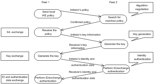
As shown in Figure 7, the main mode of IKE negotiation in phase 1 involves three pairs of messages:
· SA exchange—Used for negotiating the security policy.
· Key exchange—Used for exchanging the DH public value and other values like the random number. Key data is generated in this stage.
· ID and authentication data exchange—Used for identity authentication and authentication of data exchanged in phase 1.
The main difference between the main mode and the aggressive mode is that the aggressive mode does not provide identity protection and exchanges only three messages, rather than three pairs. The main mode provides identity protection, but it is slower.
IKE functions
IKE provides the following functions for IPsec:
· Automatically negotiates IPsec parameters such as the keys.
· Performs DH exchange when establishing an SA, making sure that each SA has a key independent of other keys.
· Automatically negotiates SAs when the sequence number in the AH or ESP header overflows, making sure that IPsec provides the anti-replay service correctly by using the sequence number.
· Provides end-to-end dynamic authentication.
· Identity authentication and management of peers influence IPsec deployment. A large-scale IPsec deployment needs the support of CAs or other institutes that manage identity data centrally.
Relationship between IKE and IPsec
Figure 8 Relationship between IKE and IPsec
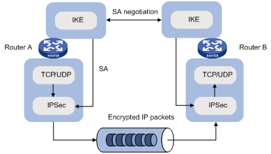
Figure 8 illustrates the relationship between IKE and IPsec:
· IKE is an application layer protocol using UDP and functions as the signaling protocol of IPsec.
· IKE negotiates SAs for IPsec and delivers negotiated parameters and generated keys to IPsec.
· IPsec uses the SAs set up through IKE negotiation for encryption and authentication of IP packets.
Protocols and standards
· RFC 2408, Internet Security Association and Key Management Protocol (ISAKMP)
· RFC 2409, The Internet Key Exchange (IKE)
· RFC 2412, The OAKLEY Key Determination Protocol
Configuration task list for IKE
Determine the following parameters prior to IKE configuration:
· The strength of the algorithms for IKE negotiation (the security protection level), including the identity authentication method, encryption algorithm, authentication algorithm, and DH group. Different algorithms provide different levels of protection. A stronger algorithm means more resistance to decryption of protected data but requires more resources. Generally, the longer the key, the stronger the algorithm.
· The pre-shared key or the PKI domain the certificate belongs to. For more information about PKI configuration, see "Configuring PKI."
To configure IKE:
|
Task |
Remarks |
|
Optional. |
|
|
Optional. Required if you want to specify an IKE proposal for an IKE peer to reference. |
|
|
Required. |
|
|
Optional. |
|
|
Optional. |
|
|
Optional. |
|
|
Optional. |
Configuring a name for the local security gateway
If the IKE negotiation peer uses the security gateway name as its ID to initiate IKE negotiation (the id-type name or id-type user-fqdn command is configured on the initiator), configure the ike local-name command in system view or the local-name command in IKE peer view on the local device. If you configure both commands, the name configured by in IKE peer view is used.
To configure a name for the local security gateway:
|
Step |
Command |
Remarks |
|
1. Enter system view. |
system-view |
N/A |
|
2. Configure a name for the local security gateway. |
ike local-name name |
Optional. By default, the device name is used as the name of the local security gateway. |
Configuring an IKE proposal
An IKE proposal defines a set of attributes describing how IKE negotiation should take place. You might create multiple IKE proposals with different preferences. The preference of an IKE proposal is represented by its sequence number. The lower the sequence number, the higher the preference.
Two peers must have at least one matching IKE proposal for successful IKE negotiation. During IKE negotiation, the initiator sends its IKE proposals to the peer, and the peer searches its own IKE proposals for a match. The search starts from the IKE proposal with the lowest sequence number and proceeds in the ascending order of sequence number until a match is found or all the IKE proposals are found mismatching. The matching IKE proposals are used to establish the secure tunnel.
The two matching IKE proposals have the same encryption algorithm, authentication method, authentication algorithm, and DH group. The SA lifetime takes the SA lifetime with a smaller value of the two.
By default, there is an IKE proposal, which has the lowest preference and uses the default encryption algorithm, authentication method, authentication algorithm, DH group, and ISAKMP SA lifetime.
When IPsec SAs are traffic expired:
· In FIPS mode, both the IPsec SAs and the corresponding IKE SAs are renegotiated.
· In non-FIPS mode, only the IPsec SAs are renegotiated.
To configure an IKE proposal:
|
Step |
Command |
Remarks |
|
1. Enter system view. |
system-view |
N/A |
|
2. Create an IKE proposal and enter its view. |
ike proposal proposal-number |
N/A |
|
3. Specify an encryption algorithm for the IKE proposal. |
encryption-algorithm { 3des-cbc | aes-cbc [ key-length ] | des-cbc } |
Optional. In FIPS mode, DES-CBC or 3DES-CBC are not supported, and the IKE proposal uses 128-bit AES-CBC for encryption by default. In non-FIPS mode, the IKE proposal uses 56-bit DES-CBC for encryption by default. |
|
4. Specify an authentication method for the IKE proposal. |
authentication-method { pre-share | rsa-signature } |
Optional. Pre-shared key by default. |
|
5. Specify an authentication algorithm for the IKE proposal. |
authentication-algorithm { md5 | sha | sha256 } |
Optional. In non-FIPS mode, the default authentication algorithm is SHA1. In FIPS mode, the default authentication algorithm is SHA256. In FIPS mode, MD5 is not supported. |
|
6. Specify a DH group for key negotiation in phase 1. |
dh { group1 | group2 | group5 | group14 } |
Optional. In FIPS mode, only group14, the 2048-bit Diffie-Hellman group can be used. In non-FIPS mode, the default group is group1, the 768-bit Diffie-Hellman group. |
|
7. Set the ISAKMP SA lifetime for the IKE proposal. |
Optional. 86400 seconds by default. Before an ISAKMP SA expires, IKE negotiates a new SA to replace it. DH calculation in IKE negotiation takes time, especially on low-end devices. To prevent SA updates from influencing normal communication, set the lifetime greater than 10 minutes. |
Configuring an IKE peer
For an IPsec policy that uses IKE, you must configure an IKE peer by performing the following tasks:
· Specify the IKE negotiation mode for the local end to use in IKE negotiation phase 1. If you obtain the IP address of the remote end dynamically and use pre-shared key authentication, H3C recommends setting the IKE negotiation mode of the local end to aggressive. When acting as the IKE negotiation responder, the local end uses the IKE negotiation mode of the remote end.
· Specify the IKE proposals for the local end to use when acting as the IKE negotiation initiator. When acting as the responder, the local end uses the IKE proposals configured in system view for negotiation.
· Configure a pre-shared key for pre-shared key authentication or a PKI domain for digital signature authentication.
· Specify the ID type for the local end to use in IKE negotiation phase 1. With pre-shared key authentication, the ID type must be IP address for main mode IKE negotiation. It can be IP address, FQDN, or user FQDN for aggressive mode IKE negotiation.
· Specify the name or IP address of the local security gateway. You perform this task only when you want to specify a special address, a loopback interface address, for example, as the local security gateway address.
· Specify the name or IP address of the remote security gateway. For the local end to initiate IKE negotiation, you must specify the name or IP address of the remote security gateway on the local end so the local end can find the remote end.
· Enable NAT traversal. If there is NAT gateway on the path for tunneling, you must configure NAT traversal at the two ends of the IPsec tunnel, because one end might use a public address while the other end uses a private address.
· Specify the DPD detector for the IKE peer.
To configure an IKE peer:
|
Step |
Command |
Remarks |
|
1. Enter system view. |
system-view |
N/A |
|
2. Create an IKE peer and enter IKE peer view. |
ike peer peer-name |
N/A |
|
3. Specify the IKE negotiation mode for phase 1. |
exchange-mode { aggressive | main } |
Optional. The default is main. In FIPS mode, the aggressive mode is not supported. |
|
4. Specify the IKE proposals for the IKE peer to reference. |
proposal proposal-number&<1-6> |
Optional. By default, an IKE peer references no IKE proposals, and, when initiating IKE negotiation, it uses the IKE proposals configured in system view. If the IKE negotiation mode in phase 1 is aggressive, only the first IKE proposal specified for the IKE peer takes effect. |
|
5. Configure a pre-shared key for pre-shared key authentication or specify a PKI domain for digital signature authentication. |
· To configure a pre-shared key: · To specify a PKI domain: |
Configure either command according to the authentication method for the IKE proposal. In FIPS mode, the simple keyword is not supported. You can configure a ciphertext pre-shared key by using the cipher key option or a plaintext pre-shared key in interactive mode. The key must contain at least eight characters comprising digits, uppercase and lowercase letters, and special characters. |
|
6. Select the ID type for IKE negotiation phase 1. |
id-type { ip | name | user-fqdn } |
Optional. By default, the ID type is IP. |
|
7. Configure a name for the local security gateway. |
local-name name |
Optional. By default, no name is configured for the local security gateway in IKE peer view, and the security gateway name configured by using the ike local-name command is used. |
|
8. Specify the name of the remote security gateway. |
remote-name name |
Optional. The remote gateway name configured with remote-name command on the local gateway must be identical to the local name configured with the local-name command on the peer. |
|
9. Enable the NAT traversal function for IPsec/IKE. |
nat traversal |
Required when a NAT gateway is present in the VPN tunnel constructed by IPsec/IKE. Disabled by default. |
|
10. Configure an IP address for the local gateway. |
local-address ip-address |
Optional. By default, it is the primary IP address of the interface referencing the security policy. |
|
11. Specify the IP addresses of the remote gateway. |
remote-address { hostname [ dynamic ] | low-ip-address [ high-ip-address ] } |
Optional. The remote IP address configured with the remote-address command on the local gateway must be identical to the local IP address configured with the local-address command on the peer. |
|
12. Set the subnet types of the two ends. |
· Set the subnet type of the local end: · Set the subnet type of the peer end: |
Optional. The default subnet type is single-subnet. Use these two commands only when the device is working together with a NetScreen device. |
|
13. Apply a DPD detector to the IKE peer. |
dpd dpd-name |
Optional. No DPD detector is applied to an IKE peer by default. For more information about DPD configuration, see "Configuring a DPD detector." |
|
|
NOTE: After modifying the configuration of an IPsec IKE peer, execute the reset ipsec sa and reset ike sa commands to clear existing IPsec and IKE SAs. Otherwise, SA re-negotiation will fail. |
Setting keepalive timers
IKE maintains the link status of an ISAKMP SA by keepalive packets. Generally, if the peer is configured with the keepalive timeout, you must configure the keepalive packet transmission interval on the local end. If the peer receives no keepalive packet during the timeout interval, the ISAKMP SA is tagged with the TIMEOUT tag (if it does not have the tag), or deleted along with the IPsec SAs it negotiated (when it has the tag already).
The keepalive timeout configured at the local end must be longer than the keepalive interval configured at the remote end. Since it seldom occurs that more than three consecutive packets are lost on a network, you can configure the keepalive timeout to be three times of the keepalive interval.
To set the keepalive timers:
|
Step |
Command |
Remarks |
|
1. Enter system view. |
system-view |
N/A |
|
2. Set the ISAKMP SA keepalive interval. |
ike sa keepalive-timer interval seconds |
No keepalive packet is sent by default. |
|
3. Set the ISAKMP SA keepalive timeout. |
ike sa keepalive-timer timeout seconds |
No keepalive packet is sent by default. |
Setting the NAT keepalive timer
If IPsec traffic needs to pass through NAT security gateways, you must configure the NAT traversal function. If no packet travels across an IPsec tunnel in a certain period of time, the NAT mapping might get aged and be deleted. This disables the tunnel beyond the NAT gateway from transmitting data to the intended end. To prevent NAT mappings from being aged, an ISAKMP SA behind the NAT security gateway sends NAT keepalive packets to its peer at a certain interval to keep the NAT session alive.
To set the NAT keepalive timer:
|
Step |
Command |
Remarks |
|
1. Enter system view. |
system-view |
N/A |
|
2. Set the NAT keepalive interval. |
ike sa nat-keepalive-timer interval seconds |
20 seconds by default. |
Configuring a DPD detector
DPD irregularly detects dead IKE peers. It works as follows:
1. When the local end sends an IPsec packet, it checks the time the last IPsec packet was received from the peer.
2. If the time interval exceeds the DPD interval, it sends a DPD hello to the peer.
3. If the local end receives no DPD acknowledgement within the DPD packet retransmission interval, it retransmits the DPD hello.
4. If the local end still receives no DPD acknowledgement after having made the maximum number of retransmission attempts (two by default), it considers the peer already dead, and clears the IKE SA and the IPsec SAs based on the IKE SA.
DPD enables an IKE entity to check the liveliness of its peer only when necessary. It generates less traffic than the keepalive mechanism, which exchanges messages periodically.
To configure a DPD detector:
|
Step |
Command |
Remarks |
|
1. Enter system view. |
system-view |
N/A |
|
2. Create a DPD detector and enter its view. |
ike dpd dpd-name |
N/A |
|
3. Set the DPD interval. |
interval-time interval-time |
Optional. 10 seconds by default. |
|
4. Set the DPD packet retransmission interval. |
time-out time-out |
Optional. 5 seconds by default. |
Disabling next payload field checking
The Next payload field is in the generic payload header of the last payload of the IKE negotiation message (the message includes multiple payloads). According to the protocol, this field must be 0 if the payload is the last payload of the packet. However, it might be set to other values on some brands of devices. For interoperability, disable the checking of this field.
To disable Next payload field checking:
|
Step |
Command |
Remark |
|
1. Enter system view. |
system-view |
N/A |
|
2. Disable Next payload field checking. |
ike next-payload check disabled |
Enabled by default. |
Displaying and maintaining IKE
|
Task |
Command |
Remarks |
|
Display IKE DPD information. |
display ike dpd [ dpd-name ] [ | { begin | exclude | include } regular-expression ] |
Available in any view. |
|
Display IKE peer information. |
display ike peer [ peer-name ] [ | { begin | exclude | include } regular-expression ] |
Available in any view. |
|
Display IKE SA information. |
display ike sa [ active | standby | verbose [ connection-id connection-id | remote-address remote-address ] ] [ | { begin | exclude | include } regular-expression ] |
Available in any view. |
|
Display IKE proposal information. |
display ike proposal [ | { begin | exclude | include } regular-expression ] |
Available in any view. |
|
Clear SAs established by IKE. |
reset ike sa [ connection-id | active | standby ] |
Available in user view. |
IKE configuration examples
For more information, see WLAN Configuration Guide.
Troubleshooting IKE
When you configure parameters to establish an IPsec tunnel, enable IKE error debugging to locate configuration problems:
<AC> debugging ike error
Proposal mismatch
Symptom
The proposals mismatch.
Analysis
The following is the debugging information:
got NOTIFY of type NO_PROPOSAL_CHOSEN
Or
drop message from A.B.C.D due to notification type NO_PROPOSAL_CHOSEN
The two parties in the negotiation have no matched proposals.
Solution
For the negotiation in phase 1, look up the IKE proposals for a match.
For the negotiation in phase 2, verify that the parameters of the IPsec policies applied on the interfaces are matched, and that the referred IPsec transform sets have a match in protocol, encryption and authentication algorithms.
Failing to establish an IPsec tunnel
Symptom
The expected IPsec tunnel cannot be established.
Analysis
Sometimes this might happen if an IPsec tunnel cannot be established or there is no way to communicate in the presence of an IPsec tunnel in an unstable network.
If ACLs of both parties are configured correctly, and proposals are also matched, the problem is usually caused by the reboot of one router after the IPsec tunnel is established.
Solution
· Use the display ike sa command to verify that both parties have established an SA in phase 1.
· Use the display ipsec sa policy command to verify that the IPsec policy on the interface has established IPsec SA.
· If the two commands show that one party has an SA, but the other does not, use the reset ipsec sa command to clear the IPsec SA that has no corresponding SA, use the reset ike sa command to clear the IKE SA that has no corresponding IKE SA, and then trigger SA re-negotiation.