- Table of Contents
-
- 07-Security Configuration Guide
- 00-Preface
- 01-Security Overview
- 02-AAA Configuration
- 03-802.1X Configuration
- 04-MAC Authentication Configuration
- 05-Portal Configuration
- 06-Port Security Configuration
- 07-User Profile Configuration
- 08-Password Control Configuration
- 09-Public Key Configuration
- 10-PKI Configuration
- 11-SSH Configuration
- 12-SSL Configuration
- 13-SSL VPN Configuration
- 14-TCP Attack Protection Configuration
- 15-ARP Attack Protection Configuration
- 16-IPsec Configuration
- 17-ALG Configuration
- 18-Firewall Configuration
- 19-Session Management Configuration
- 20-Web Filtering Configuration
- 21-User Isolation Configuration
- 22-Source IP Address Verification Configuration
- 23-FIPS Configuration
- 24-Protocol Packet Rate Limit Configuration
- 25-Attack detection and protection configuration
- Related Documents
-
| Title | Size | Download |
|---|---|---|
| 21-User Isolation Configuration | 83.80 KB |
Configuring VLAN-based user isolation
Configuring SSID-based user isolation
Displaying and maintaining user isolation
User isolation configuration example
Configuring user isolation
User isolation includes the following types:
· VLAN-based user isolation—Isolates users in the same VLAN from accessing each other at Layer 2.
· SSID-based user isolation—Isolates users using the same SSID from accessing each other at Layer 2.
VLAN-based user isolation
VLAN-based user isolation allows users to access the network, and at the same time, it isolates users from accessing each other at Layer 2 for security purposes.
When VLAN-based user isolation is enabled, an AC isolates packets from the same VLAN in the following ways:
· When an AC receives unicast, broadcast, or multicast packets from a wireless user to another wireless user, the AC determines whether to isolate the two users based on the permitted MAC address list.
· When an AC receives unicast packets from a wireless user to a wired user, the AC determines whether to isolate the two users based on the permitted MAC address list. However, the AC permits all broadcast and multicast packets from a wireless user to a wired user.
· When an AC receives unicast packets from a wired user to another wired user, the AC determines whether to isolate the two users based on the permitted MAC address list. However, the AC permits all broadcast and multicast packets from a wired user to another wired user.
· When an AC receives unicast packets from a wired user to a wireless user, the AC determines whether to isolate the two users based on the permitted MAC address list. The user-isolation permit broadcast command setting determines whether the AC permits broadcast or multicast packets (from a wired user to a wireless user).
Whether to allow unicast traffic among users in the same VLAN is also determined by the user-isolation permit unicast command. If this command is used, the AC allows the unicast traffic among users in the same VLAN regardless of whether the users' MAC addresses are in the permitted MAC address list.
For correct communication between users and the gateway, add the MAC address of the gateway to the permitted MAC address list.
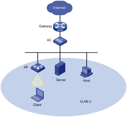
As shown in Figure 1, the wireless client, the wired server, and the wired host in VLAN 2 access the Internet through the same gateway. When VLAN-based user isolation is enabled on the AC, the following rules apply:
· If you add only the MAC address of the gateway to the permitted MAC address list, the client, server, and host are isolated at Layer 2. They can access the Internet.
· If you add only the MAC address of the client to the permitted MAC address list, the client and the server, and the client and the host, can access each other at Layer 2, but the server and the host cannot.
· If you add the MAC addresses of the gateway, the server, and the client to the permitted MAC address list, the client, the server, and the host can access one another at Layer 2. They also can access the Internet.
SSID-based user isolation
For security purposes and accounting accuracy, enable SSID-based user isolation. It disables wireless users that use the same SSID from accessing each other at Layer 2.
When SSID-based user isolation is enabled on the AC, all the wireless users using the same SSID are disabled from forwarding Layer 2 unicast or broadcast packets to each other.
Configuring VLAN-based user isolation
|
Step |
Command |
Remarks |
|
1. Enter system view. |
system-view |
N/A |
|
2. Enable user isolation for the specified VLANs. |
user-isolation vlan vlan-list enable |
By default, user isolation is disabled. |
|
3. Specify permitted MAC addresses for the specified VLANs. |
user-isolation vlan vlan-list permit-mac mac-list |
Optional. Up to 16 permitted MAC addresses can be configured for a VLAN. To avoid network disruption caused by user isolation, add the MAC address of the gateway to the permitted MAC address list, and then enable user isolation. |
|
4. Permit broadcast and multicast packets from a wired user to a wireless user. |
user-isolation permit broadcast |
Optional. By default, broadcast and multicast packets from a wired user to a wireless user are permitted. |
|
5. Permit unicast packets among users in the same VLAN. |
user-isolation permit unicast |
Optional. By default, the AC determines whether to isolate unicast packets of users in a user isolation-enabled VLAN based on the permitted MAC address list. |
Configuring SSID-based user isolation
|
Step |
Command |
Remarks |
|
1. Enter system view. |
system-view |
N/A |
|
2. Configure WLAN service template. |
wlan service-template service-template-number { clear | crypto } |
N/A |
|
3. Enable SSID-based user isolation. |
user-isolation enable |
Optional. By default, SSID-based user isolation is disabled. |
Displaying and maintaining user isolation
|
Task |
Command |
Remarks |
|
Display user isolation statistics. |
display user-isolation statistics [ vlan vlan-id ] [ | { begin | exclude | include } regular-expression ] |
Available in any view. |
|
Clear user isolation statistics. |
reset user-isolation statistics [ vlan vlan-id ] |
Available in user view. |
User isolation configuration example
Network requirements
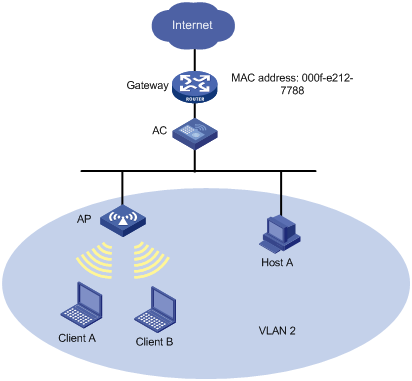
As shown in Figure 2, configure user isolation on the AC, so Client A, Client B, and Host A in VLAN 2 can access the Internet, but they cannot access one another at Layer 2.
Configuration procedure
1. Configure the AC:
# Configure the AP so that a connection can be established between the AC and AP. (Details not shown.)
For information about establishing the connection, see WLAN Configuration Guide.
<AC> system-view
# Add the MAC address of the gateway to the permitted MAC address list of VLAN 2 so that Client A, Client B, and Host A in VLAN 2 can access the Internet.
[AC] user-isolation vlan 2 permit-mac 000f-e212-7788
# Enable user isolation for VLAN 2 so that users in VLAN 2 cannot access each other at Layer 2.
[AC] user-isolation vlan 2 enable
2. Verify the configuration.
Client A, Client B, and Host A in VLAN 2 can access the Internet, but they cannot access one another at Layer 2.