- Table of Contents
-
- 07-Security Configuration Guide
- 00-Preface
- 01-Security Overview
- 02-AAA Configuration
- 03-802.1X Configuration
- 04-MAC Authentication Configuration
- 05-Portal Configuration
- 06-Port Security Configuration
- 07-User Profile Configuration
- 08-Password Control Configuration
- 09-Public Key Configuration
- 10-PKI Configuration
- 11-SSH Configuration
- 12-SSL Configuration
- 13-SSL VPN Configuration
- 14-TCP Attack Protection Configuration
- 15-ARP Attack Protection Configuration
- 16-IPsec Configuration
- 17-ALG Configuration
- 18-Firewall Configuration
- 19-Session Management Configuration
- 20-Web Filtering Configuration
- 21-User Isolation Configuration
- 22-Source IP Address Verification Configuration
- 23-FIPS Configuration
- 24-Protocol Packet Rate Limit Configuration
- 25-Attack detection and protection configuration
- Related Documents
-
| Title | Size | Download |
|---|---|---|
| 05-Portal Configuration | 1.46 MB |
Configuring portal authentication
Portal system using the local portal server
Layer 3 portal authentication process
MAC-based quick portal authentication
Portal configuration task list
Specifying a portal server for Layer 3 portal authentication
Configuring the local portal server
Customizing authentication pages
Configuring the local portal server
Enabling Layer 3 portal authentication
Controlling access of portal users
Configuring a portal-free rule
Configuring a portal-forbidden rule
Configuring the greylist feature
Configuring an authentication source subnet
Setting the maximum number of online portal users
Specifying a portal authentication domain
Configuring Layer 3 portal authentication to support Web proxy
Configuring WeChat authentication
Configuring a redirection URL for a user-requested URL
Configuring RADIUS related attributes
Specifying the NAS ID value carried in a RADIUS request
Specifying NAS-Port-Type for an interface
Specifying the NAS-Port-ID for an interface
Specifying a NAS ID profile for an interface
Specifying a source IP address for outgoing portal packets
Configuring MAC-based quick portal authentication
Configuring portal stateful failover
Associating SSID, AP, portal server, authentication domain and URL
Specifying an autoredirection URL for authenticated portal users
Configuring the NAS IP parameter in the redirection URL
Specifying the listening UDP port for portal packets
Configuring portal detection functions
Configuring online Layer 3 portal user detection
Configuring the portal server detection function
Configuring portal user information synchronization
Enabling forced logoff for user SSID switching
Enabling logging for portal packets
Specifying the parameters to be carried in the redirection URL
Configuring the format of the MAC addresses in the redirection URL
Configuring the control mode for portal user packets
Enabling host identity check through DHCP snooping entries or IP-MAC bindings
Allowing only users with DHCP-assigned IP addresses to pass portal authentication
Sending error codes for authentication failures
Enabling the local forwarding mode for authenticated portal users
Configuring portal safe-redirect
Configuring online behavior logging for portal users
Configuring support of HTTPS redirection for portal authentication
Excluding an attribute from portal protocol packets
Displaying and maintaining portal
Configuring IPv4 direct portal authentication
Configuring re-DHCP portal authentication
Configuring direct portal authentication with extended functions
Configuring re-DHCP portal authentication with extended functions
Configuring portal stateful failover
Configuring portal server detection and portal user information synchronization
Configuring direct portal authentication using local portal server
Configuring portal stateful failover with local portal servers
Configuring MAC-based quick portal authentication
Configuring IPv6 direct portal authentication
Inconsistent keys on the access device and the portal server
Incorrect server port number on the access device
Configuring portal authentication
Overview
With portal authentication, an access device redirects all users to the portal authentication page. All users can access the free services provided on the portal website. However, to access the Internet, a user must pass portal authentication.
A user can access a known portal website and enter a username and password for authentication. This authentication mode is called active authentication. There is another authentication mode, forced authentication, in which the access device forces a user who is trying to access the Internet through HTTP to log on to a portal website for authentication.
The portal feature provides the flexibility for ISPs to manage services. A portal website can, for example, present advertisements and deliver community and personalized services. In this way, broadband network providers, equipment vendors, and content service providers form an industrial ecological system.
Extended portal functions
By forcing patching and anti-virus policies, extended portal functions help users to defend against viruses. Portal authentication supports the following extended functions:
· Security check—Works after identity authentication succeeds to check whether the required anti-virus software, virus definition file, and operating system patches are installed, and whether there is any unauthorized software installed on the user host.
· Resource access restriction—Allows users passing identity authentication to access only network resources in the quarantined area, such as the anti-virus server and the patch server. Only users passing both identity authentication and security check can access restricted network resources.
Portal system components
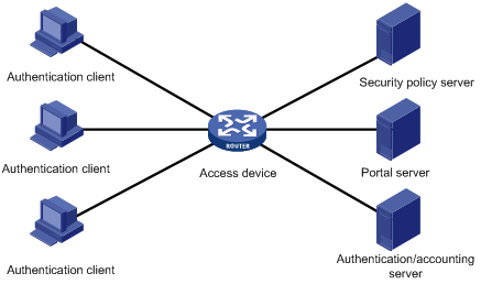
As shown in Figure 1, a typical portal system has these basic components:
· Authentication client
· Access device
· Portal server
· Authentication/accounting server
· Security policy server
Figure 1 Portal system components
Authentication client
An authentication client is an entity seeking access to network resources. It is typically an end-user terminal such as a PC. A client can use a browser or portal client software for portal authentication. Client security check is implemented through communications between the client and the security policy server.
To implement security check, the client must be the H3C iNode client.
Access device
Access devices control user access. An access device can be a switch or router that provides the following functions:
· Redirecting all HTTP requests from unauthenticated users to the portal server.
· Interacting with the portal server, the security policy server, and the authentication/accounting server for identity authentication, security check, and accounting.
· Allowing users who have passed identity authentication and security check to access granted Internet resources.
Portal server
A portal server listens to authentication requests from authentication clients and exchanges client authentication information with the access device. It provides free portal services and pushes Web authentication pages to users.
A portal server can be an entity independent of the access device or an entity embedded in the access device. In this document, the term "portal server" refers to an independent portal server, and the term "local portal server" refers to an embedded portal server.
Authentication/accounting server
An authentication/accounting server implements user authentication and accounting through interaction with the access device.
Only a RADIUS server can serve as the remote authentication/accounting server in a portal system.
Security policy server
A security policy server interacts with authentication clients and access devices for security check and resource authorization.
The components of a portal system interact as follows:
1. When an unauthenticated user enters a website address in the browser's address bar to access the Internet, the system creates an HTTP request and sends it to the access device. The access device then redirects the HTTP request to the portal server's Web authentication homepage. For extended portal functions, authentication clients must run the portal client software.
2. On the authentication homepage/authentication dialog box, the user enters and submits the authentication information, which the portal server then transfers to the access device.
3. Upon receipt of the authentication information, the access device communicates with the authentication/accounting server for authentication and accounting.
4. After successful authentication, the access device checks whether there is a corresponding security policy for the user. If not, it allows the user to access the Internet. Otherwise, the client communicates with the access device and the security policy server for security check. If the client passes the security check, the security policy server authorizes the user to access the Internet resources.
|
|
NOTE: Portal authentication supports NAT traversal whether it is initiated by a Web client or an H3C iNode client. When the portal authentication client is on a private network, but the portal server is on a public network and the access device is enabled with NAT, network address translations performed on the access device do not affect portal authentication. However, in such a case, H3C recommends using an interface's public IP address as the source address of outgoing portal packets. |
Portal system using the local portal server
In addition to using a separate device as the portal server, a portal system can also use the local portal server function of the access device to authenticate Web users directly. In this case, the portal system consists of only three components: authentication client, access device, and authentication/accounting server, as shown in Figure 2.
Figure 2 Portal system using the local portal server
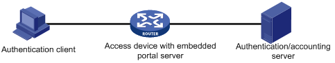
No security policy server is needed for local portal service because the portal system using the local portal server does not support extended portal functions.
The local portal server function of the access device implements only some simple portal server functions. It only allows users to log on and log off through the Web interface. It cannot take the place of an independent portal server.
Protocols used for interaction between the client and local portal server
You can use HTTP and HTTPS for interaction between an authentication client and an access device providing the local portal server function. If you use HTTP, there are potential security problems because HTTP packets are transferred in plain text. If you use HTTPS, secure data transmission is ensured because HTTPS packets are transferred in cipher text based on SSL.
Authentication page customization support
The local portal server function allows you to customize authentication pages. You can customize authentication pages by editing the corresponding HTML files, and then compress and save the files to the storage medium of the device. A set of customized authentication pages consists of the following authentication pages:
· Logon page
· Logon success page
· Online page
· Logoff success page
· Logon failure page
· System busy page
A local portal server pushes a corresponding authentication page at each authentication phase. If you do not customize the authentication pages, the local portal server pushes the default authentication pages. For information about authentication page customization rules, see "Customizing authentication pages."
Portal authentication modes
Portal authentication may work at Layer 2 or Layer 3 of the OSI model. The device supports only Layer 3 portal authentication.
You can enable Layer 3 authentication on an access device's Layer 3 interfaces that connect authentication clients. Portal authentication performed on a Layer 3 interface can be direct authentication, re-DHCP authentication, or cross-subnet authentication. In direct authentication and re-DHCP authentication, no Layer 3 forwarding devices exist between the authentication client and the access device. In cross-subnet authentication, Layer 3 forwarding devices may exist between the authentication client and the access device.
Direct authentication
Before authentication, a user manually configures a public IP address or directly obtains a public IP address through DHCP, and can access only the portal server and predefined free websites. After passing authentication, the user can access the network resources. The process of direct authentication is simpler than that of re-DHCP authentication.
Re-DHCP authentication
Before authentication, a user gets a private IP address through DHCP and can access only the portal server and predefined free websites. After passing authentication, the user is allocated a public IP address and can access the network resources. No public IP address is allocated to those who fail authentication. This solves the IP address planning and allocation problem. For example, a service provider can allocate public IP addresses to broadband users only when they access networks beyond the residential community network.
The local portal server does not support re-DHCP portal authentication. IPv6 portal authentication does not support the re-DHCP authentication mode.
Cross-subnet authentication
Cross-subnet authentication is similar to direct authentication, but it allows Layer 3 forwarding devices to be present between the authentication client and the access device.
In direct authentication, re-DHCP authentication, and cross-subnet authentication, the client's IP address is used for client identification. After a client passes authentication, the access device generates an ACL for the client based on the client's IP address to permit packets from the client to go through the access port. Because no Layer 3 devices are present between the authentication clients and the access device in direct authentication and re-DHCP authentication, the access device can directly learn the clients' MAC addresses, and can enhance the capability of controlling packet forwarding by also using the learned MAC addresses.
Portal support for EAP
Only Layer 3 portal authentication that uses a remote portal server supports EAP authentication.
Authentication by using the username and password is less secure. Digital certificate authentication is usually used to ensure higher security.
The Extensible Authentication Protocol (EAP) supports several digital certificate-based authentication methods, for example, EAP-TLS. Working together with EAP, portal authentication can implement digital certificate-based user authentication.
Figure 3 Portal support for EAP working flow diagram
![]()
As shown in Figure 3, the authentication client and the portal server exchange EAP authentication packets. The portal server and the access device exchange portal authentication packets that carry the EAP-Message attributes. The access device and the RADIUS server exchange RADIUS packets that carry the EAP-Message attributes. The RADIUS server that supports the EAP server function processes the EAP packets encapsulated in the EAP-Message attributes, and provides the EAP authentication result. During the whole EAP authentication process, the access device does not process the packets that carry the EAP-Message attributes, but only transports them between the portal server and the RADIUS server. Therefore, no additional configuration is needed on the access device.
|
|
NOTE: To use portal authentication that supports EAP, the portal server and client must be the H3C IMC portal server and the H3C iNode portal client. |
Layer 3 portal authentication process
Direct authentication and cross-subnet authentication share the same authentication process. Re-DHCP authentication has a different process because of the presence of two address allocation procedures.
Direct authentication/cross-subnet authentication process (with CHAP/PAP authentication)
Figure 4 Direct authentication/cross-subnet authentication process
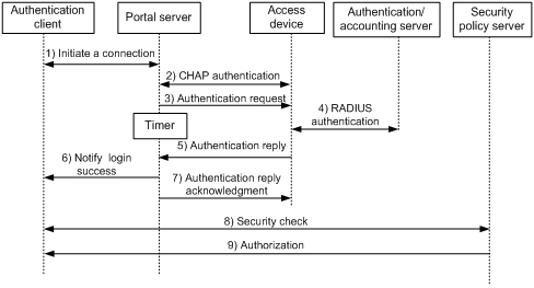
The direct authentication/cross-subnet authentication process is as follows:
1. An authentication client initiates authentication by sending an HTTP request. When the HTTP packet arrives at the access device, the access device allows it to pass if it is destined for the portal server or a predefined free website, or redirects it to the portal server if it is destined for other websites. The portal server pushes a Web authentication page to the user, and the user enters the username and password.
2. The portal server and the access device exchange CHAP messages. This step is skipped for PAP authentication.
3. The portal server assembles the username and password into an authentication request message, and it sends the message to the access device. Meanwhile, the portal server starts a timer to wait for an authentication acknowledgment message.
4. The access device and the RADIUS server exchange RADIUS packets to authenticate the user.
5. The access device sends an authentication reply to the portal server.
6. The portal server sends an authentication success message to the authentication client to notify it of logon success.
7. The portal server sends an authentication reply acknowledgment message to the access device.
With extended portal functions, the process includes additional steps:
8. The security policy server exchanges security check information with the authentication client to check whether the authentication client meets the security requirements.
9. Based on the security check result, the security policy server authorizes the user to access certain resources, and sends the authorization information to the access device. The access device then controls access of the user based on the authorization information.
Re-DHCP authentication process (with CHAP/PAP authentication)
Figure 5 Re-DHCP authentication process
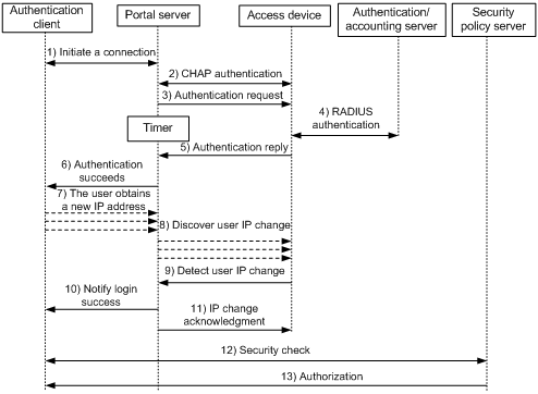
The re-DHCP authentication process is as follows:
Step 1 through step 6 are the same as those in the direct authentication/cross-subnet authentication process.
7. After receiving the authentication success message, the authentication client obtains a new public IP address through DHCP and notifies the portal server that it now has a public IP address.
8. The portal server notifies the access device that the authentication client has obtained a new public IP address.
9. Detecting the change of the IP address by examining ARP packets received, the access device notifies the portal server of the change.
10. The portal server notifies the authentication client of logon success.
11. The portal server sends a user IP address change acknowledgment message to the access device.
With extended portal functions, the process includes additional steps:
12. The security policy server exchanges security check information with the authentication client to check whether the authentication client meets the security requirements.
13. Based on the security check result, the security policy server authorizes the user to access certain resources, and sends the authorization information to the access device. The access device then controls access of the user based on the authorization information.
Authentication process with the local portal server
Figure 6 Authentication process with the local portal server
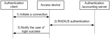
With the local portal server, the direct/cross-subnet authentication process is as follows:
1. A portal client initiates authentication by sending an HTTP request. When the HTTP packet arrives at an access device using the local portal server, it is redirected to the local portal server, which then pushes a Web authentication page for the user to enter the username and password. The listening IP address of the local portal server is the IP address of a Layer 3 interface on the access device that can communicate with the portal authentication client.
2. The access device and the RADIUS server exchange RADIUS packets to authenticate the user.
3. If the user passes authentication, the local portal server pushes a logon success page to the authentication client, informing the user of the authentication (logon) success.
Portal support for EAP authentication process
Figure 7 Portal support for EAP authentication process
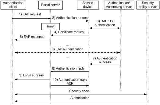
All portal authentication modes share the same EAP authentication steps. The following example uses direct portal authentication to show the EAP authentication process:
1. The authentication client sends an EAP Request/Identity message to the portal server to initiate an EAP authentication process.
2. The portal server sends a portal authentication request to the access device, and starts a timer to wait for the portal authentication reply. The portal authentication request contains several EAP-Message attributes, which are used to encapsulate the EAP packet sent from the authentication client and carry the certificate information of the client.
3. After the access device receives the portal authentication request, it constructs a RADIUS authentication request and sends the request to the RADIUS server. The EAP-Message attributes in the RADIUS authentication request are those carried in the received portal authentication request.
4. The access device sends a certificate request to the portal server according to the reply received from the RADIUS server. The certificate request also contains several EAP-Message attributes, which are used to transfer the certificate information of the RADIUS server. The EAP-Message attributes in the certificate request are those carried in the RADIUS authentication reply.
5. After receiving the certificate request, the portal server sends an EAP authentication reply to the authentication client, carrying the EAP-Message attribute values.
6. The authentication client sends another EAP request to continue the EAP authentication with the RADIUS server, during which there may be several portal authentication requests. The subsequent authentication processes are the same as that initiated by the first EAP request, except that the EAP request types vary with the EAP authentication phases.
7. After the authentication client passes the EAP authentication, the RADIUS server sends an authentication reply to the access device. This reply carries the EAP-Success message in the EAP-Message attribute.
8. The access device sends an authentication reply to the portal server. This reply carries the EAP-Success message in the EAP-Message attribute.
9. The portal server notifies the authentication client of the authentication success.
10. The portal server sends an authentication reply acknowledgment to the access device.
The remaining steps are for extended portal authentication. For more information about the steps, see the portal authentication process with CHAP/PAP authentication.
MAC-based quick portal authentication
Support for this feature depends on the device model. For more information, see About the H3C Access Controllers Configuration Guides.
Typically, users must provide username and password for portal authentication each time they access the network. Users who access the network frequently may want to pass authentication without entering username and password. To meet such requirements, portal supports a MAC-based quick authentication scheme, which is also referred to as MAC-triggered authentication.
With MAC-triggered authentication, the access device obtains the source MAC address of a user. When the network traffic of the user is below the specified threshold (1024 bytes for example), the access device allows the user to access the network without portal authentication. When the user's network traffic reaches the threshold, the access device triggers portal authentication for the user. The authentication procedure is as follows:
1. The access device sends a MAC binding query to the MAC binding server.
2. When the MAC binding server receives the query, it checks whether the MAC address is bound with a portal user account.
¡ If yes, the MAC binding server obtains the account information of the portal user, and sends the username and password of the user to the access device to initiate portal authentication. The user can pass portal authentication without entering the username and password.
¡ If not, the MAC binding server notifies the access device to perform normal portal authentication for the user. The access device redirects the subsequent HTTP packet of the user to the portal server, which provides a portal authentication page for the user. The user must enter the username and password to pass portal authentication.
MAC-triggered authentication provides a quick, effective portal authentication for users whose MAC addresses have been bound with portal user accounts on the MAC binding servers.
A MAC binding server is required for MAC-triggered authentication. The MAC-to-account bindings of portal users are recorded on the MAC binding server.
A MAC binding server performs the following functions:
· Records bindings between endpoints (identified by MAC addresses) and user accounts. The bindings facilitate user auditing.
Endpoint-to-account bindings are added to the endpoint device list of the MAC binding server in the following ways:
¡ The MAC binding server automatically learns and records the binding between an endpoint and an account. The binding does not update automatically. The endpoint is bound only to the first account that passes authentication on the endpoint, no matter how many accounts pass authentication later. To unbind the endpoint and the account, you need to delete the binding from the endpoint device list.
¡ A user manually adds endpoint-to-account bindings on the user self-service center. This method allows multiple endpoints to be bound to an account.
· Records bindings between endpoints (identified by MAC addresses) and manufacturer/device type/operating system information. The bindings facilitate endpoint auditing.
The MAC binding server automatically obtains the manufacturer, device type, and operating system information of an endpoint. The binding between the endpoint and the information obtained the first time is saved in the endpoint device list. When a user initiates authentication on the endpoint, the MAC binding server compares the current information of the endpoint with the recorded information. If inconsistency occurs, the MAC binding server logs the endpoint information conflict.
· Provides quick enabling/disabling of MAC-triggered authentication.
If MAC-triggered authentication for endpoints is enabled on the MAC binding server, you can quickly enable or disable MAC-triggered authentication for specific endpoints in the endpoint device list.
On an HP IMC portal server, you can configure the fast authentication on smart terminals function to implement MAC-triggered authentication. For more information about the configuration procedure, see the configuration manuals for the IMC portal server.
Portal stateful failover
Support for this feature depends on the device model. For more information, see About the H3C Access Controllers Configuration Guides.
Overview
Stateful failover supports hot backup of services on two devices. Stateful failover can be configured on key devices to avoid service interruptions caused by single point failures. When operating correctly, the two devices synchronize service information. If one device fails, the other device takes over the services.
To implement stateful failover, specify an stateful failover interface on each device and connect the two stateful failover interfaces through a failover link, or specify a dedicated VLAN (called the backup VLAN) on each device for stateful failover packets. When both a failover link and a backup VLAN are configured, add the physical ports at the two ends of the failover link to the backup VLAN. For more information about the stateful failover feature, see High Availability Configuration Guide.
Figure 8 Network diagram for portal stateful failover configuration
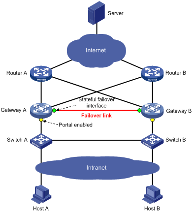
As shown in Figure 8, users have to pass portal authentication to access the Internet. To avoid portal service interruption caused by single point failures, deploy two access devices (Gateway A and Gateway B) and configure the portal stateful failover function so that they back up the portal online user information of each other through the failover link. If either one (Gateway A or Gateway B) fails, the other can guarantee the normal data communication of the online portal users and perform portal authentication for new portal users.
Basic concepts
1. Device states:
¡ Independence—A stable running status of a device when it does not establish the failover link with the other device.
¡ Synchronization—A stable running status of a device when it establishes the failover link with the other device successfully and is ready for data backup.
2. User modes:
¡ Stand-alone—Indicates that the user data is stored on the local device only. Currently, the local device is in independence state or it is in synchronization state, but it has not synchronized the user data to the peer device yet.
¡ Primary—Indicates that the user logs in from the local device, and the user data is generated on the local device. The local device is in synchronization state and ready for receiving and processing packets from the server.
¡ Secondary—Indicates that the user logs in from the peer device, and the user data is synchronized from the peer device to the local device. The local device is in synchronization state. It only receives and processes the synchronization messages and does not process packets from the server.
Portal configuration task list
To configure Layer 3 portal authentication:
Configuration prerequisites
Although the portal feature provides a solution for user identity authentication and security check, the portal feature cannot implement this solution by itself. RADIUS authentication must be configured on the access device to cooperate with the portal feature to complete user authentication.
The prerequisites for portal authentication configuration are as follows:
· The portal server and the RADIUS server have been installed and configured properly. Local portal authentication requires no independent portal server be installed.
· With re-DHCP authentication, the IP address check function of the DHCP relay agent is enabled on the access device, and the DHCP server is installed and configured properly.
· The portal client, access device, and servers can reach each other.
· With RADIUS authentication, usernames and passwords of the users are configured on the RADIUS server, and the RADIUS client configurations are performed on the access device. For information about RADIUS client configuration, see "Configuring AAA."
· To implement extended portal functions, install and configure IMC EAD, and make sure that the ACLs configured on the access device correspond to those specified for the resources in the quarantined area and for the restricted resources on the security policy server. For information about security policy server configuration on the access device, see "Configuring AAA."
For installation and configuration about the security policy server, see IMC EAD Security Policy Help.
The ACL for resources in the quarantined area and that for restricted resources correspond to isolation ACL and security ACL on the security policy server.
You can modify the authorized ACLs on the access device. However, your changes take effect only for portal users logging on after the modification.
Specifying a portal server for Layer 3 portal authentication
Perform this task to specify portal server parameters for Layer 3 portal authentication, including the portal server IP address, shared encryption key, server port, and the URL address for Web authentication. According to the networking environment, you can configure a remote portal server or a local portal server as needed.
· To configure a remote portal server, specify the IP address of the remote portal server.
· To use the local portal server of the access device, specify the IP address of a Layer 3 interface on the device as the portal server's IP address. The specified interface must be reachable to the client.
Follow these guidelines when you specify a portal server for Layer 3 authentication:
· The specified parameters of a portal server can be modified or deleted only if the portal server is not referenced on any interface.
· For local portal server configuration, the keywords key, port, server-type, and url are usually not required and, if configured, do not take effect. When using local portal servers for stateful failover in wireless environments, however, the keyword url is required and the address format must be http://ip-address/portal/logon.htm or https://ip-address/portal/logon.htm. Which address format is used depends the protocol type (HTTP or HTTPS, configured by the portal local-server command) supported by the local portal servers. The ip-address is the virtual IP address of the VRRP group to which the downlink belongs.
· When a local portal server is used, the re-DHCP portal authentication mode (redhcp) can be configured but, if configured, does not take effect.
· You can enable both IPv4 portal authentication and IPv6 portal authentication if a CMCC portal server is used. For IPv6 portal authentication to operate properly, you must specify both an IPv4 portal server and an IPv6 portal server. The IPv4 portal server is used for portal authentication, and the IPv6 portal server is used for redirecting HTTP requests from IPv6 portal users.
· The maximum number of portal servers that you can specify on the access device depends on the device model. For more information, see About the H3C Access Controllers Command References.
To specify a portal server for Layer 3 authentication:
|
Step |
Command |
Remarks |
|
1. Enter system view. |
system-view |
N/A |
|
2. Specify a portal server and configure related parameters. |
By default, no portal server is specified. Support for the ipv6 keyword and the server-type { cmcc | imc } option depends on the device model. For more information, see About the H3C Access Controllers Command References. The portal server name and URL string cannot contain any of the following characters: question mark (?), angle brackets (<>), backward slash (\), double quotation mark ("), single quotation mark ('), percent sign (%), ampersand (&), and pound sign (#). |
Configuring the local portal server
Configuring a local portal server is required only for local portal authentication. During local portal authentication, the local portal server pushes authentication pages to users. You can define the authentication pages for users. Otherwise, the default authentication pages are used during the authentication process.
In a wireless network, you can bind an SSID to a set of authentication pages. The system selects authentication pages for a user in this order: the authentication pages bound with the SSID of the user, the user-defined default authentication pages, and the system default authentication pages.
Customizing authentication pages
Customized authentication pages exist in the form of HTML files. You can compress them, and then save them in the storage medium of the access device.
A set of authentication pages includes six main authentication pages and their page elements.
The six main authentication pages are the logon page, the logon success page, the logon failure page, the online page, the system busy page, and the logoff success page.
The page elements refer to the files that the authentication pages reference, for example, back.jpg for page Logon.htm. Each main authentication page can reference multiple page elements. If you define only some of the main authentication pages, the system uses the default authentication pages for the undefined ones.
For the local portal server to operate correctly and steadily, use the following rules when customizing authentication pages:
File name rules
The names of the main authentication page files cannot be changed. You can define the names of the files other than the main authentication page files. File names and directory names are case-insensitive.
Table 1 Main authentication page file names
|
Main authentication page |
File name |
|
Logon page |
logon.htm |
|
Logon success page |
logonSuccess.htm |
|
Logon failure page |
logonFail.htm |
|
Online page Pushed after the user gets online for online notification |
online.htm |
|
System busy page Pushed when the system is busy or the user is in the logon process |
busy.htm |
|
Logoff success page |
logoffSuccess.htm |
Page request rules
The local portal server supports only Get and Post requests.
· Get requests—Used to get the static files in the authentication pages and allow no recursion. For example, if file Logon.htm includes contents that perform Get action on file ca.htm, file ca.htm cannot include any reference to file Logon.htm.
· Post requests—Used when users submit username and password pairs, log on the system, and log off the system.
Post request attribute rules
1. Observe the following requirements when editing a form of an authentication page:
¡ An authentication page can have multiple forms, but there must be one and only one form whose action is logon.cgi. Otherwise, user information cannot be sent to the local portal server.
¡ The username attribute is fixed as PtUser. The password attribute is fixed as PtPwd.
¡ Attribute PtButton is required to indicate the action that the user requests, either Logon or Logoff.
¡ A logon Post request must contain PtUser, PtPwd, and PtButton attributes.
¡ A logoff Post request must contain the PtButton attribute.
2. Authentication pages logon.htm and logonFail.htm must contain the logon Post request.
The following example shows part of the script in page logon.htm.
<form action=logon.cgi method = post >
<p>User name:<input type="text" name = "PtUser" style="width:160px;height:22px" maxlength=64>
<p>Password :<input type="password" name = "PtPwd" style="width:160px;height:22px" maxlength=32>
<p><input type=SUBMIT value="Logon" name = "PtButton" style="width:60px;" onclick="form.action=form.action+location.search;>
</form>
3. Authentication pages logonSuccess.htm and online.htm must contain the logoff Post request.
The following example shows part of the script in page online.htm.
<form action=logon.cgi method = post >
<p><input type=SUBMIT value="Logoff" name="PtButton" style="width:60px;">
</form>
Page file compression and saving rules
· A set of authentication page files must be compressed into a standard zip file. The name of a zip file can contain only letters, numerals, and underscores. The zip file of the default authentication pages must be saved with name defaultfile.zip.
· The set of authentication pages must be located in the root directory of the zip file.
· You can transfer zip files to the device through FTP or TFTP. You must save the default authentication pages file in the root directory of the device. You can save other authentication files in the root directory or the portal directory under the root directory of the device.
Examples of zip files on the device:
<Sysname> dir
Directory of flash:/portal/
0 -rw- 1405 Feb 28 2008 15:53:31 ssid2.zip
1 -rw- 1405 Feb 28 2008 15:53:20 ssid1.zip
2 -rw- 1405 Feb 28 2008 15:53:39 ssid3.zip
3 -rw- 1405 Feb 28 2008 15:53:44 ssid4.zip
2540 KB total (1319 KB free)
File size and content rules
The following size and content requirements for authentication pages allows the system to push customized authentication pages smoothly:
· The size of the zip file of each set of authentication pages, including the main authentication pages and the page elements, must be no more than 500 KB.
· The size of a single page, including the main authentication page and its page elements, must be no more than 50 KB before being compressed.
· Page elements can contain only static contents such as HTML, JS, CSS, and pictures.
Logging off a user who closes the logon success or online page
After a user passes authentication, the system pushes the logon success page named logonSuccess.htm. If the user initiates another authentication through the logon page, the system pushes the online page named online.htm. You can configure the device to forcibly log off the user when the user closes either of these two pages. To do so, add the following contents in logonSuccess.htm and online.htm:
1. Reference to JS file pt_private.js.
2. Function pt_unload(), which is used to trigger page unloading.
3. Function pt_submit(), the event handler function for Form.
4. Function pt_init(), which is for triggering page loading.
The following is a script example with the added contents highlighted in gray:
<html>
<head>
<script type="text/javascript" language="javascript" src="pt_private.js"></script>
</head>
<body onload="pt_init();" onbeforeunload="return pt_unload();">
... ...
<form action=logon.cgi method = post onsubmit="pt_submit()">
... ...
</body>
</html>
If a user refreshes the logon success or online page, or jumps to another website from either of the pages, the device also logs off the user.
Only Microsoft IE, Mozilla Firefox, and Apple Safari browsers support the device to log off the user when the user closes the logon success or online page. Google Chrome, Opera, and other browsers do not support this function.
Make sure the browser of an authentication client permits pop-ups or permits pop-ups from the access device. Otherwise, the user cannot log off by closing the logon success or online page, and can only click Cancel to return back to the logon success or online page.
Redirecting authenticated users to a specific webpage
To make the device automatically redirect authenticated users to a specific webpage, do the following in logon.htm and logonSuccess.htm:
1. In logon.htm, set the target attribute of Form to blank.
See the contents in gray:
<form method=post action=logon.cgi target="blank">
2. Add the function for page loading pt_init() to logonSucceess.htm.
See the contents in gray:
<html>
<head>
<title>LogonSuccessed</title>
<script type="text/javascript" language="javascript" src="pt_private.js"></script>
</head>
<body onload="pt_init();" onbeforeunload="return pt_unload();">
... ...
</body>
</html>
|
|
NOTE: H3C recommends using Microsoft IE 6.0 or later on the authentication clients. |
Configuring the local portal server
To make the local portal server take effect, specify the protocol to be used for communication between the portal client and local portal server.
Configuration prerequisites
To configure the local portal server to support HTTPS, complete the following configurations first:
· Configure PKI policies, obtain the CA certificate, and apply for a local certificate. For more information, see "Configuring PKI."
· Configure the SSL server policy, and specify the PKI domain to be used, which is configured in the above step. For more information, see "Configuring SSL."
When you specify the protocol for the local portal server to support, the local portal server loads the default authentication page file, which is supposed to be saved in the root directory of the device. Therefore, to make sure the local portal server uses the user-defined default authentication pages, you must edit and save them properly or else the system default authentication pages are used.
Configuration procedure
To configure the local portal server:
|
Step |
Command |
Remarks |
|
1. Enter system view. |
system-view |
N/A |
|
2. Configure the protocol type for the local portal server to support and load the default authentication page file. |
portal local-server { http | https server-policy policy-name } |
By default, the local portal server does not support any protocol. |
|
3. Configure a binding between one or more SSIDs and an authentication page file. |
portal local-server bind ssid ssidname&<1-10> file filename |
Optional. By default, no binding is configured. The file to be bound to the SSIDs must exist. |
|
4. Configure the welcome banner of the default authentication pages of the local portal server. |
portal server banner banner-string |
Optional. No welcome banner by default. |
In Layer 3 cross-subnet portal authentication mode, an AC cannot obtain the SSID of a client associated with an AP. In this case, the system does not support binding SSIDs to an authentication page file. For more information about SSID, see WLAN Configuration Guide.
Enabling Layer 3 portal authentication
You must first enable portal authentication on an access interface before it can perform portal authentication for connected clients.
Configuration guidelines
· The destination port number that the access device uses for sending unsolicited packets to the portal server must be the same as the port number that the remote portal server actually uses.
· The portal server and its parameters can be deleted or modified only when the portal server is not referenced by any interface.
· Cross-subnet authentication mode (portal server server-name method layer3) does not require Layer 3 forwarding devices between the access device and the authentication clients. However, if Layer 3 forwarding devices exist between the authentication client and the access device, you must select the cross-subnet portal authentication mode.
· In re-DHCP authentication mode, a client can use a public IP address to send packets before passing portal authentication. However, responses to the packets are restricted.
· An IPv6 portal server does not support the re-DHCP portal authentication mode.
· You can enable both an IPv4 portal server and an IPv6 portal server for Layer 3 portal authentication on an interface, but you cannot enable two IPv4 or two IPv6 portal servers on the interface.
Configuration prerequisites
Before enabling Layer 3 portal authentication on an interface, make sure that:
· An IP address is configured for the interface.
· The portal server to be referenced on the interface exists.
Configuration procedure
To enable Layer 3 portal authentication:
|
Step |
Command |
Remarks |
|
1. Enter system view. |
system-view |
N/A |
|
2. Enter interface view. |
interface interface-type interface-number |
The interface must be a Layer 3 interface. |
|
3. Enable Layer 3 portal authentication on the interface. |
portal server server-name method { direct | layer3 | redhcp } |
Not enabled by default. If you use a CMCC portal server to authenticate IPv6 portal users, the portal server specified in this command must be an IPv6 CMCC server. |
Controlling access of portal users
Configuring a portal-free rule
A portal-free rule allows specified users to access specified external websites without portal authentication.
The matching items for a portal-free rule include the source and destination IP address, TCP/UDP port number, source MAC address, inbound interface, and VLAN. Packets matching a portal-free rule do not trigger portal authentication, so users sending the packets can directly access the specified external websites.
Configuration guidelines
· If you specify both a VLAN and an interface in a portal-free rule, the interface must belong to the VLAN. Otherwise, the rule does not take effect.
· You cannot configure two or more portal-free rules with the same filtering criteria. Otherwise, the system prompts that the rule already exists.
· Regardless of whether portal authentication is enabled or not, you can only add or remove a portal-free rule. You cannot modify it.
Configuration procedure
To configure a portal-free rule:
|
Step |
Command |
Remarks |
|
1. Enter system view. |
system-view |
N/A |
|
2. Configure a portal-free rule. |
· To configure an IPv4 portal-free rule: · To configure an IPv6 portal-free rule: |
Configure at least one command. Support for the tcp, udp, and wlan ssid keywords in the command depends on the device model. Support for IPv6 portal-free rules depends on the device model. For more information, see About the H3C Access Controllers Configuration Guides. |
Configuring a portal-forbidden rule
Support for this feature depends on the device model. For more information, see About the H3C Access Controllers Configuration Guides.
A portal forbidden rule can deny users' access to some specific resources. It contains such criteria as IP address, domain name, TCP port number, or UDP port number. Any packet that matches the rule cannot be forwarded.
To configure a portal-forbidden rule:
|
Command |
|
|
1. Enter system view. |
system-view |
|
2. Configure a portal-forbidden rule. |
portal forbidden-rule rule-number [ source wlan ssid ssid-name [ hotspot hotspot-name ] ] destination { ip { hostname | ip-address [ mask { mask-length | netmask } ] } | { { tcp | udp } port-number } } * |
Configuring the greylist feature
To perform no accounting on user traffic destined for specific websites, configure the greylist feature. When the greylist feature is enabled, the device does not send statistics on user traffic that matches greylist rules to the AAA server for accounting.
To configure the greylist feature:
|
Step |
Command |
Remarks |
|
1. Enter system view. |
system-view |
N/A |
|
2. Enter interface view. |
interface interface-type interface-number |
N/A |
|
3. Enable the greylist feature. |
portal grey-rule enable |
By default, the greylist feature is disabled. |
|
4. Return to system view. |
quit |
N/A |
|
5. Configure a greylist rule. |
portal grey-rule rule-number [ source { ip ip-address [ mask { mask-length | mask } ] | wlan ssid ssid-name [ hotspot hotspot-name ] } * ] destination { domain domain-name | ip ip-address [ mask { mask-length | mask } ] | tcp tcp-port-number | udp udp-port-number } * |
By default, no greylist rules are configured. |
Configuring an authentication source subnet
By configuring authentication source subnets, you specify that only HTTP packets from users on the authentication source subnets can trigger portal authentication. If an unauthenticated user is not on any authentication source subnet, the access device discards all the user's HTTP packets that do not match any portal-free rule.
Configuration of authentication source subnets applies to only cross-subnet authentication. In direct authentication mode, the authentication source subnet is 0.0.0.0/0. In re-DHCP authentication mode, the authentication source subnet of an interface is the subnet to which the private IP address of the interface belongs.
To configure an authentication source subnet:
|
Step |
Command |
Remarks |
|
1. Enter system view. |
system-view |
N/A |
|
2. Enter interface view. |
interface interface-type interface-number |
N/A |
|
3. Configure an authentication source subnet. |
portal auth-network { ipv4-network-address { mask-length | mask } | ipv6 ipv6-network-address prefix-length } |
Optional. By default, the authentication source IPv4 and IPv6 subnets are 0.0.0.0/0 and ::/0, respectively, which mean that users from any subnets must pass portal authentication. Support for the IPv6 parameters depends on the device model. For more information, see About the H3C Access Controllers Command References. |
You can configure up to 32 authentication source subnets by executing the portal auth-network command.
Setting the maximum number of online portal users
You can use this feature to control the total number of online portal users in the system.
If the maximum number of online portal you set is less than that of the current online portal users, the limit can be set successfully and does not impact the online portal users, but the system does not allow new portal users to log on until the number drops down below the limit.
To set the maximum number of online portal users allowed in the system:
|
Step |
Command |
Remarks |
|
1. Enter system view. |
system-view |
N/A |
|
2. Set the maximum number of online portal users. |
portal max-user max-number |
The default maximum number of online portal users allowed depends on the device model. For more information, see About the H3C Access Controllers Command References. |
Specifying a portal authentication domain
After you specify an authentication domain for portal users on an interface, the device uses the authentication domain for AAA of all portal users on the interface, ignoring the domain names carried in the usernames. This allows you to specify different authentication domains for different interfaces as needed.
To specify the authentication domain for portal users on an interface:
|
Step |
Command |
Remarks |
|
1. Enter system view. |
system-view |
N/A |
|
2. Enter interface view. |
interface interface-type interface-number |
N/A |
|
3. Specify an authentication domain for portal users on the interface. |
portal domain [ ipv6 ] domain-name |
By default, no authentication domain is specified for portal users. Support for the ipv6 keyword depends on the device model. For more information, see About the H3C Access Controllers Command References. |
The device selects the authentication domain for a portal user on an interface in this order: the authentication domain specified for the interface, the authentication domain carried in the username, and the system default authentication domain. For information about the default authentication domain, see "Configuring AAA."
Configuring Layer 3 portal authentication to support Web proxy
Support for this feature depends on the device model. For more information, see About the H3C Access Controllers Configuration Guides.
By default, only HTTP requests from non-proxy users can trigger Layer 3 portal authentication. Proxied HTTP requests cannot trigger Layer 3 portal authentication, and they are silently dropped. To allow such HTTP requests to trigger portal authentication, configure the port numbers of the Web proxy servers on the device.
Configuration prerequisites
Different clients may have different Web proxy configurations. The following prerequisites must be met for these clients to trigger portal authentication:
|
Web proxy configuration on clients |
Configuration prerequisites |
|
Scenario 1: All or some clients use a Web proxy, and the portal server's IP address is not a proxy exception. |
· If you use an IMC portal server, perform the following configurations on the IMC portal server: ¡ Select NAT as the type of the IP group associated with the portal device. ¡ Specify the proxy server's IP address as the IP address after NAT. ¡ Configure the port group to support NAT · The portal server and the Web proxy server have IP connectivity to each other. |
|
Scenario 2: All or some clients use a Web proxy, and the portal server's IP address is a proxy exception. |
If you use an IMC portal server, configure the IP group and port group to not support NAT. |
|
Scenario 3: All clients use a Web proxy server, but only some clients specify the portal server's IP address as a proxy exception. |
· If you use an IMC portal server, add the client IP addresses to two IP groups according to whether the portal server's IP address is a proxy exception, and then configure the IP groups and the port group according to scenarios 1 and 2. · The portal server and the Web proxy server have IP connectivity to each other. |
Configuration procedure
To configure Layer 3 portal authentication to support a Web proxy:
|
Step |
Command |
Remarks |
|
1. Enter system view. |
system-view |
N/A |
|
2. Add a Web proxy server port number. |
portal web-proxy port port-number |
By default, no Web proxy server port number is configured, and proxied HTTP requests cannot trigger portal authentication. |
If a user's browser uses the WPAD protocol to discover Web proxy servers, add the port numbers of the Web proxy servers on the device, and configure portal-free rules to allow user packets destined for the IP address of the WPAD server to pass without authentication.
If the Web proxy server port 80 is added on the device, clients that do not use a proxy server can trigger portal authentication only when they access a reachable host enabled with the HTTP service.
Authorized ACLs to be assigned to users who have passed portal authentication must contain a rule that permits the Web proxy server's IP address. Otherwise, the users cannot receive heartbeat packets from the remote portal server.
Configuring WeChat authentication
The WeChat authentication feature allows the servers behind the BSLB, such as WeChat and App Store servers, to be accessed by portal users before authentication. After the users follow WeChat official accounts or download Apps, they can initiate portal authentication to access the Internet.
The optimized captive-bypass feature applies only to iOS mobile devices. The device automatically pushes the portal authentication page to iOS mobile devices when they are connected to the network. Users can press the home button to return to the desktop without triggering portal authentication, and the Wi-Fi connection is not terminated.
To configure WeChat authentication:
|
Step |
Command |
Remarks |
|
1. Enter system view. |
system-view |
N/A |
|
2. Specify the domain name that is to be free of portal authentication. |
portal user-url user-url-string free |
By default, no domain name is configured to be free of portal authentication. |
|
3. Configure specific mobile devices to be in silent mode before portal authentication. |
portal silent { android | ios user-agent [ user-agent [ reply-file file-name ] ] } |
By default, no mobile device is configured to be in silent mode. |
|
4. Enable the optimized captive-bypass feature for iOS mobile devices. |
portal silent ios optimize |
Optional. By default, the optimized captive-bypass feature is disabled for iOS mobile devices. |
Configuring a redirection URL for a user-requested URL
Use this feature to redirect users that access different websites to different portal authentication pages.
To configure a redirection URL for a user-requested URL:
|
Step |
Command |
Remarks |
|
1. Enter system view. |
system-view |
N/A |
|
2. Configure a redirection URL for a user-requested URL. |
portal user-url user-url-string redirect-url url-string |
By default, no redirection URLs are configured for user-requested URLs. |
Configuring RADIUS related attributes
Specifying the NAS ID value carried in a RADIUS request
If the device uses a RADIUS server for authentication, authorization, and accounting of portal users, when a portal user logs on from an interface, the device sends a RADIUS request that carries the NAS-Identifier attribute to the RADIUS server. The RADIUS server uses the NAS-Identifier attribute in the RADIUS request to identify the device.
You can specify the NAS-identifier attribute value to be carried in a RADIUS request in system view or interface view. The device prefers the value specified in interface view. If no NAS ID is configured for the interface, the device uses the NAS ID configured in system view.
To specify the NAS ID value carried in a RADIUS request:
|
Step |
Command |
Remarks |
|
1. Enter system view. |
system-view |
N/A |
|
2. Specify the NAS ID value carried in a RADIUS request. |
· In system view: · In interface view: a. interface interface-type interface-number b. portal nas-id nas-id |
By default, the device name configured by the sysname command is used as the NAS ID. For information about the sysname command, see Fundamentals Command Reference. |
Specifying NAS-Port-Type for an interface
NAS-Port-Type is a standard RADIUS attribute for indicating a user access port type. With this attribute specified on an interface, when a portal user logs on from the interface, the device uses the specified NAS-Port-Type value as that in the RADIUS request to be sent to the RADIUS server. If NAS-Port-Type is not specified, the device uses the access port type obtained.
If there are multiple network devices between the Broadband Access Server (the portal authentication access device) and a portal client, the BAS may not be able to obtain a user's correct access port information. For example, for a wireless client using portal authentication, the access port type obtained by the BAS may be the type of the wired port that authenticates the user. To make sure that the BAS delivers the right access port information to the RADIUS server, specify the NAS-Port-Type according to the practical access environment.
To specify the NAS-Port-Type value for an interface:
|
Step |
Command |
Remarks |
|
1. Enter system view. |
system-view |
N/A |
|
2. Enter interface view. |
interface interface-type interface-number |
N/A |
|
3. Specify the NAS-Port-Type value for the interface. |
portal nas-port-type { ethernet | wireless } |
Not configured by default. |
Specifying the NAS-Port-ID for an interface
If the device uses a RADIUS server for authentication, authorization, and accounting of portal users, when a portal user logs on from an interface, the device sends a RADIUS request that carries the NAS-Port-ID attribute to the RADIUS server. The portal server configuration determines the usage of the NAS-Port-ID attribute.
To specify the NAS-Port-ID value carried in a RADIUS request sent from an interface:
|
Step |
Command |
Remarks |
|
1. Enter system view. |
system-view |
N/A |
|
2. Enter interface view. |
interface interface-type interface-number |
N/A |
|
3. Configure the NAS-Port-ID value. |
portal nas-port-id nas-port-id-value |
By default, no NAS-Port-ID value is specified for an interface, and the device uses the information obtained from the physical interface where the portal user accesses as the NAS-Port-ID value in a RADIUS request. |
Specifying a NAS ID profile for an interface
In some networks, user access points are identified by their access VLANs. Network carriers need to use NAS-identifiers to identify user access points. With the NAS ID profile specified on an interface, when a user logs in from the interface, the access device checks the specified profile to obtain the NAS ID that is bound with the access VLAN. The value of this NAS ID is used as the NAS-identifier attribute in the RADIUS packets to be sent to the RADIUS server.
The NAS ID profile defines the binding relationship between VLANs and NAS IDs. A NAS ID-VLAN binding is defined by the nas-id id-value bind vlan vlan-id command, which is described in detail in AAA configuration commands in the Security Command Reference.
If no NAS-ID profile is specified for an interface or no matching binding is found in the specified profile:
· If the NAS ID is configured using the portal nas-id command, the device uses the configured NAS ID as that of the interface.
· If the interface has no NAS ID configured, the device uses the device name as the interface NAS ID.
To configure a NAS ID profile on an interface:
|
Step |
Command |
Remarks |
|
1. Enter system view. |
system-view |
N/A |
|
2. Create a NAS ID profile and enter NAS ID profile view. |
aaa nas-id profile profile-name |
For more information about the command, see Security Command Reference. |
|
3. Bind a NAS ID with a VLAN. |
nas-id nas-identifier bind vlan vlan-id |
For more information about the command, see Security Command Reference. |
|
4. Return to system view. |
quit |
N/A |
|
5. Enter interface view. |
interface interface-type interface-number |
N/A |
|
6. Specify a NAS ID profile for the interface. |
portal nas-id-profile profile-name |
By default, an interface is specified with no NAS ID profile. |
Specifying a source IP address for outgoing portal packets
After you specify a source IP address for outgoing portal packets on an interface, the IP address is used as the source IP address of packets that the access device sends to the portal server, and the destination IP address of packets that the portal server sends to the access device.
To specify a source IP address for outgoing portal packets:
|
Step |
Command |
Remarks |
|
1. Enter system view. |
system-view |
N/A |
|
2. Enter interface view. |
interface interface-type interface-number |
N/A |
|
3. Specify a source IP address for outgoing portal packets. |
portal nas-ip { ipv4-address | ipv6 ipv6-address } |
Optional. By default, no source IP address is specified, and the IP address of the user logon interface is used as the source IP address of outgoing portal packets. Support for the IPv6 parameters depends on the device model. For more information, see About the H3C Access Controllers Command References. In NAT environments, H3C recommends specifying the interface's public IP address as the source IP address of outgoing portal packets. |
Specifying the device ID
Support for this feature depends on the device model. For more information, see About the H3C Access Controllers Configuration Guides.
Perform this task if a CMCC portal server is used.
After the access device is configured with a device ID, the redirection URL that the access device sends to a portal client carries the wlanacname parameter and an XML value. The XML value becomes the configured device ID. The portal server uses this configured device ID to determine which access device a portal client is using.
To specify the device ID:
|
Step |
Command |
Remarks |
|
1. Enter system view. |
system-view |
N/A |
|
2. Specify the device ID. |
portal device-id id-value |
By default, no device ID is specified for a device. |
Configuring MAC-based quick portal authentication
Support for this feature depends on the device model. For more information, see About the H3C Access Controllers Configuration Guides.
To configure MAC-based quick portal authentication (MAC-triggered authentication), you must complete the following tasks:
· Configure basic Layer 3 portal authentication.
· Specify the IP address and port number of a MAC binding server.
· Enable MAC-triggered authentication on the interface enabled with portal authentication.
· Specify the MAC binding server as a portal server. For configuration information, see "Specifying a portal server for Layer 3 portal authentication."
After MAC-triggered authentication takes effect, the access device checks a user's traffic at a specific interval (specified by the period period-value option). Before the user traffic reaches the threshold (specified by the threshold threshold-value option), the user can access the external network without authentication. When the user traffic reaches the threshold, the device performs MAC-triggered authentication.
To configure MAC-triggered authentication:
|
Step |
Command |
Remarks |
|
1. Enter system view. |
system-view |
N/A |
|
2. Specify a MAC binding server. |
portal mac-trigger server ip ip-address [ port port-number ] |
By default, no MAC binding server is specified. |
|
3. Enter interface view. |
interface interface-type interface-number |
N/A |
|
4. Enable MAC-triggered authentication. |
portal mac-trigger enable [ period period-value ] [ threshold threshold-value ] |
By default, MAC-triggered authentication is disabled. |
|
5. Configure the NAS-Port-Type value carried in RADIUS accounting requests. |
portal mac-trigger nas-port-type value |
Optional. By default, the port link type determines the NAS-Port-Type value. |
|
6. Set the maximum attempts for transmitting a MAC binding query and the transmission interval. |
portal mac-trigger binding-retry retry-times interval interval-value |
Optional. By default, the maximum number of transmission attempts is 3, and the transmission interval is 1 second. |
Configuring portal stateful failover
|
|
CAUTION: · Specifying or changing the device ID of a device will log off all online users on the device. Therefore, perform the configuration only when necessary and, after the configuration, save the configuration and restart the device. · When two devices are running in stateful failover mode (one active, the other standby), do not delete the configured backup source IP addresses. Otherwise, online users on the backup may not be able to receive packets from the server. |
Support for this feature depends on the device model. For more information, see About the H3C Access Controllers Configuration Guides.
To implement stateful failover for portal, configure VRRP for traffic switchover, and perform the following configurations for service backup on each of the two devices that back up each other:
· Specify an interface for backing up portal services, which is referred to as portal service backup interface in this document, and enable portal on the portal service backup interface.
· Specify the portal group to which the portal service backup interface belongs. Be sure to specify the same portal group for the portal service backup interfaces that back up each other on the two devices.
· Specify the device ID. Make sure the device ID of the local device is different from that of the peer device.
· Specify the backup source IP address for outgoing RADIUS packets as the source IP address for RADIUS packets that is configured on the peer device, so that the peer device can receive packets from the server. (This configuration is optional.)
· Specify the backup VLAN, and enable stateful failover on the VLAN interface. For related configuration, see High Availability Configuration Guide.
After the stateful failover state of the two devices changes from independence to synchronization and the portal group takes effect, the two devices start to back up the data of online portal users for each other.
Configuration guidelines
· In stateful failover mode, the device does not support re-DHCP portal authentication on the portal service backup interface.
· In stateful failover mode, if a user on either device is logged out, information about the user on the other device is deleted, too. You can log off a user on the device or on the portal server. For example, you can use the cut connection and portal delete-user commands on the device to log off users.
· The AAA and portal configuration must be consistent on the two devices that back up each other. For example, you must configure the same portal server on the two devices.
Configuration procedure
To configure stateful failover:
|
Step |
Command |
Remarks |
|
1. Enter system view. |
system-view |
N/A |
|
2. Enter interface view. |
interface interface-type interface-number |
N/A |
|
3. Specify the portal group to which the portal service backup interface belongs. |
portal backup-group group-id |
By default, the portal service backup interface does not belong to any portal group. The portal service backup interfaces on the two devices for stateful failover must belong to the same portal group. |
|
4. Return to system view. |
quit |
N/A |
|
5. Specify the device ID in stateful failover mode. |
nas device-id device-id |
By default, the device ID is 1. For more information about the command, see Security Command Reference. |
|
6. Specify a backup source IP address for outgoing RADIUS packets. |
· Approach 1: · Approach 2: a. radius scheme radius-scheme-name b. nas-backup-ip ip-address |
Optional. Use either approach. By default, no backup source IP address is specified. You do not need to specify the backup source IP address if the device uses the virtual IP address of the VRRP group to which the uplink belongs as the source IP address of outgoing RADIUS packets. For more information about the command, see Security Command Reference. |
Associating SSID, AP, portal server, authentication domain and URL
Perform this task to associate an SSID and AP with a portal server, an authentication domain, and an autoredirection URL. A wireless user using the specified SSID and AP uses the specified portal server, authentication domain, and autoredirection URL with specific URL parameters carried for portal authentication.
The associations take effect when the following conditions are met:
· The specified portal server and authentication domain exist.
· A portal-free rule is configured to ensure that the portal server can receive packets from the device.
When a wireless user accesses an external network, the device looks for the portal server and authentication domain associated with the SSID and AP the user uses. If no match is found, the device uses the portal server enabled on the user connected interface, and the authentication domain configured in system view.
After the wireless user passes authentication, the device looks for the associated URL. If no match is found, the device uses the URL configured by using the portal redirect-url command.
To associate an SSID and AP with a portal server, an authentication domain, and an autoredirection URL with specific URL parameters carried:
|
Step |
Command |
Remarks |
|
1. Enter system view. |
system-view |
N/A |
|
2. Associate an SSID and AP name with a portal server, an authentication domain, and an autoredirection URL. |
portal [ ipv6 ] wlan ssid ssid-name [ spot spot-name ] { server server-name [ domain domain-name ] | redirect-url url-value [ wait-time value ] | redirect-url-param { nas-id param-name | nas-ip param-name | user-ip param-name | user-mac param-name [ des-encrypt ] | ap-mac param-name [ des-encrypt ] | ac-name param-name | ssid-name param-name } * } * |
By default, an SSID and AP name are not associated with any portal server, authentication domain, or autoredirection URL with specific URL parameters carried. |
Specifying an autoredirection URL for authenticated portal users
If you specify an autoredirection URL on the access device, after an unauthenticated user passes portal authentication through the portal authentication page, the access device redirects the user to the URL after a specific period of time.
When no autoredirection URL is specified for authenticated portal users, an authenticated user is usually redirected to the URL the user entered in the address bar before portal authentication. However, with local portal authentication, if the URL a user entered in the address bar before portal authentication is more than 255 characters, the user cannot be redirected to the page of the URL after passing portal authentication.
To use this feature for remote Layer 3 portal authentication, the portal server must be an IMC portal server that supports the page auto-redirection function.
To specify an autoredirection URL for authenticated portal users:
|
Step |
Command |
Remarks |
|
1. Enter system view. |
system-view |
N/A |
|
2. Specify an autoredirection URL for authenticated portal users. |
portal redirect-url url-string [ wait-time period ] |
By default, an authenticated user is redirected to the URL the user typed in the address bar before portal authentication. The wait-time period option is effective only on local portal authentication. |
Configuring the NAS IP parameter in the redirection URL
Perform this task to configure the NAS IP to be carried in the redirection URL.
In a MAC-BAC environment, the NAS IP in the redirection URL sent by the BAS AC to a user must be the IP address of the master AC. When receiving a user HTTP request, the portal server uses the NAS IP in the URL to identify the access device and sends portal requests to the access device.
This configuration takes effect only after you configure the redirection URL to carry the NAS IP parameter by using the portal url-param include nas-ip command.
If you execute the portal url-param include nas-ip command, the NAS IP in the redirection URL is the following:
· IP address configured by the portal url-param nas-ip command in this task. For example, if you specify the IP address 10.0.0.1 in this command, the redirection URL is http://10.0.0.20/portal?nasip=10.0.0.1.
· IP address configured by the portal nas-ip command for outgoing portal packets. For more information, see "Specifying a source IP address for outgoing portal packets."
If you do not execute the portal url-param include nas-ip command, the redirection URL does not carry the NAS IP parameter.
To configure the NAS IP parameter in the redirection URL:
|
Step |
Command |
Remarks |
|
1. Enter system view. |
system-view |
N/A |
|
2. Enter interface view. |
interface interface-type interface-number |
N/A |
|
3. Configure the NAS IP parameter in the redirection URL. |
portal url-param nas-ip ip-address |
By default, NAS IP in the redirection URL is not configured. |
Specifying the listening UDP port for portal packets
By default, the listening UDP port for portal packets on the device is 2000. In a MAC-BAC environment, you can modify the listening port on the BAS AC for portal packets from the master AC if port 2000 is used by another application.
To specify the listening UDP port for portal packets:
|
Step |
Command |
Remarks |
|
1. Enter system view. |
system-view |
N/A |
|
2. Specify the listening UDP port for portal packets. |
portal port listen-port |
By default, the listening UDP port for portal packets is 2000. |
Configuring portal detection functions
Configuring online Layer 3 portal user detection
This feature is available only for the direct portal authentication configured on a Layer 3 interface.
With online portal user detection enabled on an interface, the device periodically sends probe packets (ARP requests) to the portal users on the interface to check whether the portal users are still online, to find portal users who get offline without logging off.
· If the device receives a reply from a portal user before sending probe packets to the portal user for the maximum number of times, it considers that the portal user is online and keeps sending probe packets to the portal user.
· If the device receives no reply from a portal user after sending probe packets to the portal user for the maximum number of times, it considers that the portal user is offline, stops sending probe packets to the portal user, and deletes the user.
To configure online Layer 3 portal user detection:
|
Step |
Command |
Remarks |
|
1. Enter system view. |
system-view |
N/A |
|
2. Enter interface view. |
interface interface-type interface-number |
N/A |
|
3. Configure online Layer 3 portal user detection. |
access-user detect type arp retransmit number interval interval |
Not configured by default. In stateful failover mode, the actual interval for sending probe packets is the sum of probe intervals configured on the two devices. |
|
|
NOTE: Adjust the maximum number of transmission attempts and the interval of sending probe packets according to the actual network conditions. |
Configuring the portal server detection function
During portal authentication, if the communication between the access device and portal server is broken, new portal users are not able to log on and the online portal users are not able to log off. To address this problem, the access device needs to be able to detect the reachability changes of the portal server quickly and take corresponding actions to deal with the changes. For example, once detecting that the portal server is unreachable, the access device allows portal users to access network resources without authentication. This function is referred to as portal authentication bypass. It allows for flexible user access control.
With the portal server detection function, the device can detect the status of a specific portal server. The specific configurations include:
1. Detection methods (you can choose either or both)
¡ Probing HTTP connections—The access device periodically sends TCP connection requests to the HTTP service port of the portal servers configured on its interfaces. If the TCP connection with a portal server can be established, the access device considers that the probe succeeds (the HTTP service of the portal server is open and the portal server is reachable). If the TCP connection cannot be established, the access device considers that the probe fails and the portal server is unreachable.
¡ Probing portal heartbeat packets—A portal server that supports the portal heartbeat function (only the IMC portal server supports this function) sends portal heartbeat packets to portal access devices periodically. If an access device receives a portal heartbeat packet or an authentication packet within a probe interval, the access device considers that the probe succeeds and the portal server is reachable. Otherwise, it considers that the probe fails and the portal server is unreachable.
2. Probe parameters
¡ Probe interval—Interval at which probe attempts are made.
¡ Maximum number of probe attempts—Maximum number of consecutive probe attempts allowed. If the number of consecutive probes reaches this value, the access device considers that the portal server is unreachable.
3. Actions to be taken when the server reachability status changes (you can choose one or more)
¡ Sending a trap message—When the status of a portal server changes, the access device sends a trap message to the NMS. The trap message contains the portal server name and the current state of the portal server.
¡ Sending a log—When the status of a portal server changes, the access device sends a log message. The log message indicates the portal server name and the current state and original state of the portal server.
¡ Disabling portal authentication (enabling portal authentication bypass)—When the device detects that a portal server is unreachable, it disables portal authentication on the interfaces that use the portal server (allows all portal users on the interfaces to access network resources). When the device receives from the portal server portal heartbeat packets or authentication packets (such as logon requests and logout requests), it re-enables the portal authentication function.
¡ Redirecting portal users to another portal server—When the detected portal server is unreachable, the device redirects portal users to the redirection URL of the portal server specified by using the redirect-server server-name option.
You can configure any combination of the configuration items described as needed, with respect to the following:
· If both detection methods are specified, a portal server is regarded as unreachable as long as one detection method fails, and an unreachable portal server is regarded as recovered only when both detection methods succeed.
· If multiple actions are specified, the access device executes all the specified actions when the status of a portal server changes.
· The detection function configured for a portal server takes effect on an interface only after you enable portal authentication and reference the portal server on the interface.
· The portal authentication bypass function is not supported on an interface where different portal servers are specified for different SSID-and-AP associations.
To configure the portal server detection function:
|
Step |
Command |
Remarks |
|
1. Enter system view. |
system-view |
N/A |
|
2. Configure the portal server detection function. |
portal server server-name server-detect method { http | portal-heartbeat } * action { log | permit-all | redirect-server server-name | trap } * [ interval interval ] [ retry retries ] |
Not configured by default. The portal server specified in the command must exist and must be an IPv4 portal server. |
The portal heartbeat detection method works only when the portal server supports the portal server heartbeat function. Only the IMC portal server supports the portal server heartbeat function. To implement detection with this method, you also need to configure the portal server heartbeat function on the IMC portal server and make sure that the product of interval and retry is greater than or equal to the portal server heartbeat interval. H3C recommends configuring the interval to be greater than the portal server heartbeat interval configured on the portal server.
Configuring portal user information synchronization
Once the device loses communication with a portal server, the portal user information on the device and that on the portal server may be inconsistent after the communication resumes. To solve this problem, the device provides the portal user information synchronization function. This function is implemented by sending and detecting the portal synchronization packet. The process is as follows:
1. The portal server sends the online user information to the access device in a user synchronization packet at the user heartbeat interval, which is set on the portal server.
2. Upon receiving the user synchronization packet, the access device checks the user information carried in the packet with its own. If the device finds a nonexistent user in the packet, it informs the portal server of the information, and the portal server deletes the user. If the device finds that one of its users does not appear in the user synchronization packets within N consecutive synchronization probe intervals (N is equal to the value of retries configured in the portal server user-sync command), it considers that the user does not exist on the portal server and logs the user off.
To configure the portal user information synchronization function:
|
Step |
Command |
Remarks |
|
1. Enter system view. |
system-view |
N/A |
|
2. Configure the portal user information synchronization function. |
portal server server-name user-sync [ interval interval ] [ retry retries ] |
Not configured by default. The portal server specified in the command must exist and must be an IPv4 portal server. This function can take effect only when the specified portal server is referenced on the interface connecting the users. |
The user information synchronization function requires that a portal server supports the portal user heartbeat function. Only the IMC portal server supports the portal user heartbeat function. To implement the portal user synchronization function, you also need to configure the user heartbeat function on the portal server and make sure that the product of interval and retry is greater than or equal to the portal user heartbeat interval. H3C recommends configuring the interval to be greater than the portal user heartbeat interval configured on the portal server.
For redundant user information on the device—information for users who are considered nonexistent on the portal server, the device deletes the information during the (N+1)th interval, where N is equal to the value of retries configured in the portal server user-sync command.
Logging off portal users
Logging off a user terminates the authentication process for the user or removes the user from the authenticated users list.
To log off portal users:
|
Step |
Command |
Remarks |
|
1. Enter system view. |
system-view |
N/A |
|
2. Log off users. |
portal delete-user { ipv4-address | all | interface interface-type interface-number | ipv6 ipv6-address } |
Support for the IPv6 parameters depends on the device model. For more information, see About the H3C Access Controllers Command References. |
Enabling forced logoff for user SSID switching
This function logs off a wireless portal user after the user switches SSIDs.
To enable forced logoff for user SSID switching:
|
Step |
Command |
Remarks |
|
1. Enter system view. |
system-view |
N/A |
|
2. Enable forced logoff for user SSID switching. |
portal wlan ssid-switch logoff |
By default, a wireless portal user is not logged off after switching SSIDs. |
Enabling logging for portal packets
You can enable logging for portal packets for maintenance purposes, or disable this feature to avoid impact on the system performance.
|
Step |
Command |
Remarks |
|
1. Enter system view. |
system-view |
N/A |
|
2. Enable logging for portal packets. |
portal log packet |
By default, portal packet logging is disabled to avoid impacting system performances. |
Specifying the parameters to be carried in the redirection URL
You can specify the following parameters that the redirection URL carries, and customize the parameter names:
· nas-id—Carries the NAS ID parameter.
· nas-ip—Carries the NAS IP parameter.
· nas-port-id—Carries the NAS port ID parameter.
· user-mac—Carries the user MAC parameter.
· ap-mac—Carries the AP MAC parameter.
· des-encrypt—Specifies DES to encrypt user or AP MAC address in the redirection URL. If you do not specify this keyword, the redirection URL contains plaintext user or AP MAC address.
· user-url—Carries the URL that an authenticated user is redirected to.
· user-ip—Carries the user IP parameter.
· user-vlan—Carries the user VLAN parameter.
· ac-name—Carries the AC name parameter.
· ssid—Carries the SSID parameter.
To specify the parameters to be carried in the redirection URL:
|
Step |
Command |
Remarks |
|
1. Enter system view. |
system-view |
N/A |
|
2. Configure carrying parameters in the redirection URL. |
By default, parameters carried in the redirection URL vary with the server type. · For the CMCC server, the redirection URL carries the user IP (user-ip), AC name (ac-name), and SSID (ssid) parameters. · For the IMC server, the redirection URL carries only the user IP (user-ip) parameter. · For the local portal server, the redirection URL carries the user IP (user-ip), AC name (ac-name), and SSID (ssid) parameters. |
|
|
3. Configure a DES key for the parameter carried in the redirect URL. |
portal url-param des-key { simple | cipher } key |
Optional. By default, the DES key is 12345678. |
|
4. Enter interface view. |
interface interface-type interface-number |
N/A |
|
5. Specify a parameter to be carried in the redirection URL. |
portal url-param include { nas-id | nas-ip | nas-port-id | { user-mac | ap-mac } [ des-encrypt ] | user-url | user-ip | user-vlan | ac-name | ssid } [ param-name param-name ] |
By default, the redirection URL does not carry any parameters. |
Configuring the format of the MAC addresses in the redirection URL
Perform this task to configure the format of the user MAC address or the AP MAC address in the redirection URL.
To configure the MAC address format in the redirection URL:
|
Step |
Command |
Remarks |
|
1. Enter system view. |
system-view |
N/A |
|
2. Enter interface view. |
interface interface-type interface-number |
N/A |
|
3. Configure the format of the MAC addresses in the redirection URL. |
portal url-param { user-mac | ap-mac } format { with-2-hyphen | with-5-hyphen | no-hyphen } { lowercase | uppercase } |
By default, the user MAC address or AP MAC address in the redirection URL uses the six-section format (with-5-hyphen) and uppercase letters. |
Configuring the control mode for portal user packets
The device can control portal user packets based on MAC addresses or based on both IP and MAC addresses.
In MAC control mode, after an IPv4 or IPv6 portal user passes portal authentication on an interface, both IPv4 and IPv6 packets of the user can pass the interface.
In IP+MAC control mode, after an IPv4 portal user passes portal authentication on an interface, only the IPv4 packets of the user can pass the interface. After an IPv6 portal user passes portal authentication on an interface, only the IPv6 packets of the user can pass the interface.
To configure the control mode for portal user packets:
|
Step |
Command |
Remarks |
|
1. Enter system view. |
system-view |
N/A |
|
2. Enter interface view. |
interface interface-type interface-number |
N/A |
|
3. Configure the control mode for portal user packets. |
portal control-mode { mac | ip-mac } |
By default, the control mode is IP+MAC. |
Enabling host identity check through DHCP snooping entries or IP-MAC bindings
Support for this feature depends on the device model. For more information, see About the H3C Access Controllers Configuration Guides.
When the device serves as a Layer 2 device, it might be unable to learn ARP entries. Therefore, the device cannot perform host identity check through ARP entries or IP-MAC binding entries for clients. In this scenario, you can enable host identity check through DHCP snooping entries or IP-MAC binding entries. Only the portal users whose host information exists in the DHCP snooping entries or IP-MAC binding entries are allowed to continue portal authentication. For more information about DHCP snooping entries, see Layer 3 Configuration Guide. For more information about IP-MAC binding entries, see "Configuring source IP address verification."
To enable host identity check through DHCP snooping entries or IP-MAC bindings:
|
Step |
Command |
Remarks |
|
1. Enter system view. |
system-view |
N/A |
|
2. Enable host identity check through DHCP snooping entries or IP-MAC bindings. |
portal host-check { dhcp-snooping | wlan } |
By default, the device performs host identity check through ARP entries. |
Configuring Web redirect
With the Web redirect function configured on an interface, a user's first Web request is redirected to a specific webpage. Then, the user can access network resources. After a specific period of time, if the user sends a Web access request again, the system will push the specified webpage to the user again.
This function can be used, for example, by a hotel or a network carrier to push advertisement pages to customers periodically.
Like portal, the Web redirect function uses the Web request redirection mechanism to push a webpage to users, but it does not authenticate users and therefore no authentication related configuration is needed.
You cannot configure both the portal function and the Web redirect function on an interface.
To configure the Web redirect function:
|
Step |
Command |
Remarks |
|
1. Enter system view. |
system-view |
N/A |
|
2. Enter interface view. |
interface interface-type interface-number |
N/A |
|
3. Configure the Web redirect function on the interface. |
web-redirect url url-string [ interval interval ] |
By default, Web redirect is disabled. After you modify the redirection URL address, online users will not be redirected to the new URL until the current redirection interval expires. Users who access Web for the first time after the modification are redirected to the new URL. |
Allowing only users with DHCP-assigned IP addresses to pass portal authentication
This feature allows only users with DHCP-assigned IP addresses to pass portal authentication. Users with static IP addresses cannot pass portal authentication to come online. Use this feature to ensure that only users with valid IP addresses can access the network.
To allow only users with DHCP-assigned IP addresses to pass portal authentication:
|
Step |
Command |
Remarks |
|
1. Enter system view. |
system-view |
N/A |
|
2. Enter interface view. |
interface interface-type interface-number |
N/A |
|
3. Allow only users with DHCP-assigned IP addresses to pass portal authentication |
portal user-address dhcp-alloc-only |
By default, both users with DHCP-assigned IP addresses and users with static IP addresses can pass portal authentication to come online. |
Sending error codes for authentication failures
The CMCC server requires the device to send error codes that indicate reasons for user authentication failures. Perform this task to meet this requirement if the type of the portal server is CMCC.
To send error codes for authentication failures:
|
Step |
Command |
Remarks |
|
1. Enter system view. |
system-view |
N/A |
|
2. Send error codes for authentication failures. |
portal server server-name include-error-message |
By default, the device does not send error codes for authentication failures. |
Enabling the local forwarding mode for authenticated portal users
When the local forwarding mode is enabled, APs forward traffic of authenticated portal users, instead of sending the traffic to the AC for forwarding. Configure this feature to reduce the burden of the AC.
To enable the local forwarding mode for authenticated portal users:
|
Step |
Command |
Remarks |
|
1. Enter system view. |
system-view |
N/A |
|
2. Enter interface view. |
interface interface-type interface-number |
N/A |
|
3. Enable the local forwarding mode for authenticated portal users. |
portal forwarding-mode local |
By default, APs send traffic of authenticated portal users to the AC, and the AC forwards the traffic. |
Configuring portal safe-redirect
Portal safe-redirect filters HTTP requests by HTTP request method, browser type (in HTTP User Agent), and destination URL, and redirects only the permitted HTTP requests. This reduces the risk that the portal Web server cannot respond to HTTP requests because of overload.
Table 2 Browser types supported by portal safe-redirect
|
Browser type |
Description |
|
Safari |
Apple browser |
|
Chrome |
Google browser |
|
Firefox |
Firefox browser |
|
UC |
UC browser |
|
QQBrowser |
QQ browser |
|
LBBROWSER |
Cheetah browser |
|
TaoBrowser |
Taobao browser |
|
Maxthon |
Maxthon browser |
|
BIDUBrowser |
Baidu browser |
|
MSIE 10.0 |
Microsoft IE 10.0 browser |
|
MSIE 9.0 |
Microsoft IE 9.0 browser |
|
MSIE 8.0 |
Microsoft IE 8.0 browser |
|
MSIE 7.0 |
Microsoft IE 7.0 browser |
|
MSIE 6.0 |
Microsoft IE 6.0 browser |
|
MetaSr |
Sogou browser |
To configure portal safe-redirect:
|
Step |
Command |
Remarks |
|
1. Enter system view. |
system-view |
N/A |
|
2. Enable portal safe-redirect. |
portal safe-redirect enable |
By default, the portal safe-redirect feature is disabled. |
|
3. Specify an HTTP request method permitted by portal safe-redirect. |
portal safe-redirect method { get | post } |
By default, no HTTP request method permitted by portal safe-redirect is specified. HTTP requests with the GET or POST request method are permitted. |
|
4. Specify a browser type permitted by portal safe-redirect. |
portal safe-redirect user-agent user-agent-string |
Optional. By default, no browser types are specified. The device can redirect HTTP requests sent by all supported browsers (see Table 2) after portal safe-redirect is enabled. |
|
5. Configure a URL forbidden by portal safe-redirect. |
portal safe-redirect forbidden-url user-url-string |
Optional. By default, no forbidden URLs are configured. The device can redirect HTTP requests with any URLs. |
Configuring online behavior logging for portal users
This feature enables the device to record online behaviors of portal users and periodically send a specified number of the logs to the log server for auditing purposes.
To configure online behavior logging for portal users:
|
Step |
Command |
Remarks |
|
1. Enter system view. |
system-view |
N/A |
|
2. Enable online behavior logging for portal users. |
portal audit enable |
By default, online behavior logging is disabled for portal users. |
|
3. Set the interval for sending portal user online behavior logs to the log server and the maximum number of the logs to be sent in each interval. |
portal audit { interval interval | count number } * |
By default, the device sends a maximum of 50 portal user online behavior logs to the log server every three seconds. |
Configuring support of HTTPS redirection for portal authentication
Perform this task to enable the device to redirect HTTPS requests from portal users.
To support HTTPS redirection for portal authentication:
|
Step |
Command |
Remarks |
|
1. Enter system view. |
system-view |
N/A |
|
2. Specify an SSL server policy for HTTPS redirection. |
portal https-redirect ssl-server-policy policy-name |
By default, no SSL server policy is specified for HTTPS redirection. The device does not redirect HTTPS requests from portal users. |
Excluding an attribute from portal protocol packets
Support of the portal authentication server for portal protocol attributes varies by the server type. During MAC-trigger authentication, the device and the server cannot communicate if the device sends the portal authentication server a packet that contains an attribute unsupported by the server.
To address this issue, you can configure portal protocol packets to not carry the attributes unsupported by the portal authentication server.
To exclude an attribute from portal protocol packets for a portal authentication server:
|
Step |
Command |
Remarks |
|
1. Enter system view. |
system-view |
N/A |
|
2. Enter interface view. |
portal mac-trigger exclude-attribute attribute-number |
By default, no attributes are excluded from portal protocol packets. |
Displaying and maintaining portal
|
Task |
Command |
Remarks |
|
Display the ACLs on a specific interface. |
display portal acl { all | dynamic | static } interface interface-type interface-number [ | { begin | exclude | include } regular-expression ] |
Available in any view. |
|
Display portal connection statistics on a specific interface or all interfaces. |
display portal connection statistics { all | interface interface-type interface-number } [ | { begin | exclude | include } regular-expression ] |
Available in any view. |
|
Display information about a portal-free rule or all portal-free rules. |
display portal free-rule [ rule-number ] [ | { begin | exclude | include } regular-expression ] |
Available in any view. |
|
Display the portal configuration of a specific interface. |
display portal interface interface-type interface-number [ | { begin | exclude | include } regular-expression ] |
Available in any view. |
|
Display configuration information about the local portal server. |
display portal local-server [ | { begin | exclude | include } regular-expression ] |
Available in any view. |
|
Display information about a specific portal server or all portal servers. |
display portal server [ server-name ] [ | { begin | exclude | include } regular-expression ] |
Available in any view. |
|
Display portal server statistics on a specific interface or all interfaces. |
display portal server statistics { all | interface interface-type interface-number } [ | { begin | exclude | include } regular-expression ] |
Available in any view. |
|
Display TCP spoofing statistics. |
display portal tcp-cheat statistics [ | { begin | exclude | include } regular-expression ] |
Available in any view. |
|
Display information about portal users on a specific interface or all interfaces. |
display portal user { all | interface interface-type interface-number } [ | { begin | exclude | include } regular-expression ] |
Available in any view. |
|
Display information about users redirected by the Web redirect function. |
display web-redirect user [ | { begin | exclude | include } regular-expression ] |
Available in any view. |
|
Clear portal connection statistics on a specific interface or all interfaces. |
reset portal connection statistics {all | interface interface-type interface-number } |
Available in user view. |
|
Clear portal server statistics on a specific interface or all interfaces. |
reset portal server statistics { all | interface interface-type interface-number } |
Available in user view. |
|
Clear TCP spoofing statistics. |
reset portal tcp-cheat statistics |
Available in user view. |
Portal configuration examples
Configuring IPv4 direct portal authentication
Network requirements
As shown in Figure 9, the wireless user (Client) belongs to VLAN 1 and the AP belongs to VLAN 3. The AC performs direct portal authentication for wireless users. Before portal authentication, the wireless user can access only the portal server. After passing portal authentication, the user can access Internet resources.
Use a RADIUS server as the authentication/accounting server.
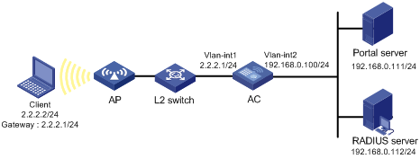
Configuration prerequisites and guidelines
· Configure IP addresses for the client, AC, and servers as shown in Figure 9, and make sure they have IP connectivity between each other.
· Configure the RADIUS server properly to provide authentication/accounting services for users.
Configuring the portal server on IMC 3.60
This section uses IMC PLAT 3.20-R2602P13 and IMC UAM 3.60-E6301.
1. Configure the portal server:
a. Log in to IMC, and then click the Service tab.
b. From the navigation tree, select Portal Service Management > Server to enter the portal server configuration page, as shown in Figure 10.
c. Configure the portal parameters as needed.
This example uses the default values.
d. Click OK.
Figure 10 Portal server configuration
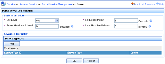
2. Configure an IP address group:
a. From the navigation tree, select Portal Service Management > IP Group to enter the portal IP address group configuration page.
b. Click Add to enter the page shown in Figure 11.
c. Enter the IP group name.
d. Enter the start IP address and end IP address of the IP group.
Make sure that the client's IP address is in the IP group.
e. Select a service group.
By default, the group Ungrouped is used.
f. Select the IP group type Normal.
g. Click OK.
Figure 11 Adding an IP address group

3. Add a portal device:
a. From the navigation tree, select Portal Service Management > Device to enter the portal device configuration page.
b. Click Add to enter the page shown in Figure 12.
c. Enter the device name AC.
d. Enter the IP address of the AC's interface connected to the client.
e. Enter the key, which must be the same as that configured on the access device (AC).
f. Specify whether to enable IP address reallocation.
This example uses direct portal authentication. Therefore, select No from the Reallocate IP list.
g. Set whether to support the portal server heartbeat and user heartbeat functions.
In this example, select No for both Support Server Heartbeat and Support User Heartbeat.
h. Click OK.
Figure 12 Adding a portal device
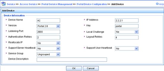
4. Associate the portal device with the IP address group:
a. As shown in Figure 13, click the icon in the Port Group Information Management column of device AC to enter the port group configuration page.
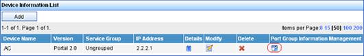
b. On the port group configuration page, click Add to enter the page shown in Figure 14. Perform the following configurations:
c. Enter the port group name.
d. Select the configured IP address group from the IP Group list. The IP address used by the client to access the network must be within this IP address group.
e. Use the default settings for other parameters.
f. Click OK.
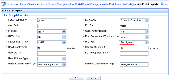
5. From the navigation tree, select Service Parameters > Validate System Configuration to validate the configurations.
Configuring the portal server on IMC 5.0
This section uses IMC PLAT 5.0 (E0101) and IMC UAM 5.0 (E0101).
1. Configure the portal server:
a. Log in to IMC and click the Service tab.
b. From the navigation tree, select User Access Manager > Portal Service Management > Server to enter the portal server configuration page, as shown in Figure 15.
c. Configure the portal server parameters as needed. This example uses the default settings.
d. Click OK.
Figure 15 Portal server configuration
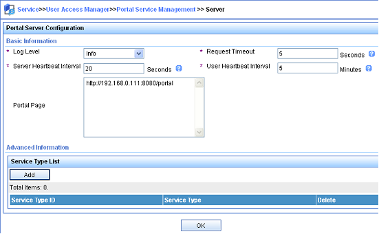
2. Configure the IP address group:
a. From the navigation tree, select User Access Manager > Portal Service Management > IP Group to enter the portal IP address group configuration page.
b. Click Add to enter the page shown in Figure 16.
c. Enter the IP group name.
d. Enter the start IP address and end IP address of the IP group.
Make sure that the client's IP address is in the IP group.
e. Select a service group.
By default, the group Ungrouped is used.
f. Select the IP group type Normal.
g. Click OK.
Figure 16 Adding an IP address group
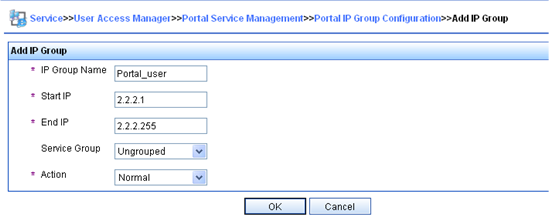
3. Add a portal device:
a. From the navigation tree, select User Access Manager > Portal Service Management > Device to enter the portal device configuration page.
b. Click Add to enter the page shown in Figure 17.
c. Enter the device name AC.
d. Enter the IP address of the router's interface connected to the user.
e. Enter the key, which must be the same as that configured on the access device (AC).
f. Set whether to enable IP address reallocation.
This example uses direct portal authentication. Therefore, select No from the Reallocate IP list.
g. Select whether to support server heartbeat and user heartbeat functions.
In this example, select No for both Support Server Heartbeat and Support User Heartbeat.
h. Click OK.
Figure 17 Adding a portal device
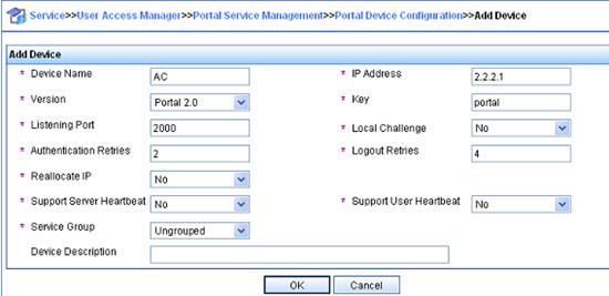
4. Associate the portal device with the IP address group:
a. As shown in Figure 18, click the icon in the Port Group Information Management column of device AC to enter the port group configuration page.
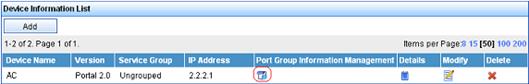
b. On the port group configuration page, click Add to enter the page shown in Figure 19.
c. Enter the port group name.
d. Select the configured IP address group. The client's IP address must be within this IP address group.
e. Use the default settings for other parameters.
f. Click OK.
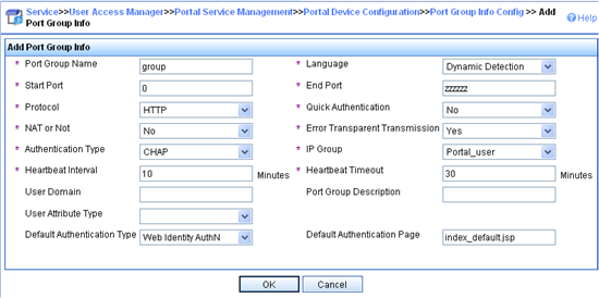
5. From the navigation tree, select User Access Manager > Service Parameters > Validate System Configuration to validate the configurations.
Configuring the AC
1. Configure a RADIUS scheme:
# Create a RADIUS scheme named rs1 and enter its view.
<AC> system-view
[AC] radius scheme rs1
# Configure the server type for the RADIUS scheme. When using the IMC server, you must configure the RADIUS server type as extended.
[AC-radius-rs1] server-type extended
# Specify the primary authentication server and primary accounting server, and configure the keys for communication with the servers.
[AC-radius-rs1] primary authentication 192.168.0.112
[AC-radius-rs1] primary accounting 192.168.0.112
[AC-radius-rs1] key authentication simple radius
[AC-radius-rs1] key accounting simple radius
# Specify that the ISP domain name should not be included in the username sent to the RADIUS server.
[AC-radius-rs1] user-name-format without-domain
[AC-radius-rs1] quit
2. Configure an authentication domain:
# Create an ISP domain named dm1 and enter its view.
[AC] domain dm1
# Configure the ISP domain to use RADIUS scheme rs1.
[AC-isp-dm1] authentication portal radius-scheme rs1
[AC-isp-dm1] authorization portal radius-scheme rs1
[AC-isp-dm1] accounting portal radius-scheme rs1
[AC-isp-dm1] quit
3. Configure portal authentication:
# Configure the portal server as follows:
¡ Name: newpt
¡ IP address: 192.168.0.111
¡ Key: portal (in plaintext)
¡ Port number: 50100
¡ URL: http://192.168.0.111:8080/portal
[AC] portal server newpt ip 192.168.0.111 key simple portal port 50100 url http://192.168.0.111:8080/portal
# Configure a portal-free rule to allow access from the AC to any destinations without portal authentication. This configuration is required only on the AC module.
[AC] portal free-rule 0 source interface bridge-aggregation 1 destination any
# On the interface connected to the client, specify the authentication domain dm1 for portal users and enable portal authentication.
[AC] interface vlan-interface 1
[AC–Vlan-interface1] portal domain dm1
[AC–Vlan-interface1] portal server newpt method direct
[AC–Vlan-interface1] quit
Configuring re-DHCP portal authentication
Network requirements
As shown in Figure 20, the wireless user (Client) belongs to VLAN 10 and AP belongs to VLAN 3.
The AC performs re-DHCP authentication for wireless users. The client obtains an IP address from the DHCP server. Before portal authentication, the DHCP server assigns a private IP address to the client. After the client passes portal authentication, it gets a public IP address from the DHCP server and can access Internet resources.
Use a RADIUS server as the authentication/accounting server. On the IMC, specify the internal subnet as the authentication subnet.
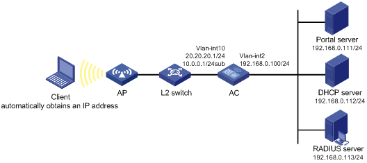
Configuration prerequisites and guidelines
· Configure IP addresses for the AC and servers as shown in Figure 20, and make sure that the client, AC, and servers have IP connectivity between each other.
· Configure the RADIUS server properly to provide authentication/accounting services for users.
Configure a public address pool (20.20.20.0/24, in this example) and a private address pool (10.0.0.0/24, in this example) on the DHCP server. The configuration steps are omitted. For more information about DHCP configuration information, see Layer 3 Configuration Guide.
Configure the AC as a DHCP relay agent and configure a primary IP address (a public IP address) and a secondary IP address (a private IP address) for the portal-enabled interface.
Configuration procedure
1. Configure a RADIUS scheme on the AC:
# Create a RADIUS scheme named rs1, and enter its view.
<AC> system-view
[AC] radius scheme rs1
# Set the server type for the RADIUS scheme. When using the IMC server, you must set the server type to extended.
[AC-radius-rs1] server-type extended
# Specify the primary authentication server and primary accounting server, and configure the keys for communication with the servers.
[AC-radius-rs1] primary authentication 192.168.0.113
[AC-radius-rs1] primary accounting 192.168.0.113
[AC-radius-rs1] key authentication simple radius
[AC-radius-rs1] key accounting simple radius
# Specify that the ISP domain name should not be included in the username sent to the RADIUS server.
[AC-radius-rs1] user-name-format without-domain
[AC-radius-rs1] quit
2. Configure an authentication domain on the AC:
# Create an ISP domain named dm1 and enter its view.
[AC] domain dm1
# Configure the ISP domain to use RADIUS scheme rs1.
[AC-isp-dm1] authentication portal radius-scheme rs1
[AC-isp-dm1] authorization portal radius-scheme rs1
[AC-isp-dm1] accounting portal radius-scheme rs1
[AC-isp-dm1] quit
3. Configure portal authentication on the AC:
# Configure the portal server as follows:
¡ Name: newpt
¡ IP address: 192.168.0.111
¡ Key: portal (in plaintext)
¡ Port number: 50100
¡ URL: http://192.168.0.111:8080/portal
[AC] portal server newpt ip 192.168.0.111 key simple portal port 50100 url http://192.168.0.111:8080/portal
# Configure a portal-free rule to allow access from the AC to any destinations without portal authentication. (Optional. This configuration is required if the AC is a wireless service module in a switch.)
[AC] portal free-rule 0 source interface bridge-aggregation 1 destination any
# Configure the AC as a DHCP relay agent, and enable the invalid address check function.
[AC] dhcp enable
[AC] dhcp relay server-group 0 ip 192.168.0.112
[AC] interface vlan-interface 10
[AC–Vlan-interface10] ip address 20.20.20.1 255.255.255.0
[AC–Vlan-interface10] ip address 10.0.0.1 255.255.255.0 sub
[AC-Vlan-interface10] dhcp select relay
[AC-Vlan-interface10] dhcp relay server-select 0
[AC-Vlan-interface10] dhcp relay address-check enable
# On the interface connected to the client, specify the authentication domain dm1 for portal users, and enable re-DHCP portal authentication.
[AC-Vlan-interface10] portal domain dm1
[AC–Vlan-interface10] portal server newpt method redhcp
[AC–Vlan-interface10] quit
Configuring direct portal authentication with extended functions
Network requirements
As shown in Figure 21, the wireless user (Client) belongs to VLAN 10 and the AP belongs to VLAN 3.
The AC performs direct portal authentication for wireless users. If the client fails security check after it passes identity authentication, the client can access only subnet 192.168.0.0/24. After the client passes security check, the client can access Internet resources.
Use a RADIUS server as the authentication/accounting server.
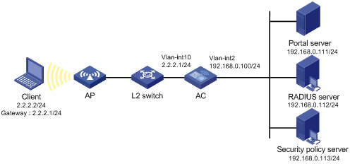
Configuration prerequisites
Configure IP addresses for the client, AC, and servers as shown in Figure 21 and make sure they have IP connectivity between each other.
Configure the RADIUS server properly to provide authentication/accounting services for users.
Configuration procedure
1. Configure a RADIUS scheme on the AC:
# Create a RADIUS scheme named rs1 and enter its view.
<AC> system-view
[AC] radius scheme rs1
# Set the server type for the RADIUS scheme. When using the IMC server, you must set the server type to extended.
[AC-radius-rs1] server-type extended
# Specify the primary authentication server and primary accounting server, and configure the keys for communication with the servers.
[AC-radius-rs1] primary authentication 192.168.0.112
[AC-radius-rs1] primary accounting 192.168.0.112
[AC-radius-rs1] key accounting simple radius
[AC-radius-rs1] key authentication simple radius
[AC-radius-rs1] user-name-format without-domain
# Configure the IP address of the security policy server.
[AC-radius-rs1] security-policy-server 192.168.0.113
[AC-radius-rs1] quit
2. Configure an authentication domain on the AC:
# Create an ISP domain named dm1 and enter its view.
[AC] domain dm1
# Configure the ISP domain to use RADIUS scheme rs1.
[AC-isp-dm1] authentication portal radius-scheme rs1
[AC-isp-dm1] authorization portal radius-scheme rs1
[AC-isp-dm1] accounting portal radius-scheme rs1
[AC-isp-dm1] quit
3. On the AC, configure the ACL (ACL 3000) for resources on subnet 192.168.0.0/24 and the ACL (ACL 3001) for Internet resources.
[AC] acl number 3000
[AC-acl-adv-3000] rule permit ip destination 192.168.0.0 0.0.0.255
[AC-acl-adv-3000] quit
[AC] acl number 3001
[AC-acl-adv-3001] rule permit ip
[AC-acl-adv-3001] quit
Make sure you specify ACL 3000 as the isolation ACL and ACL 3001 as the security ACL on the security policy server.
4. Configure extended portal authentication on the AC:
# Configure the portal server as follows:
¡ Name: newpt
¡ IP address: 192.168.0.111
¡ Key: portal (in plaintext)
¡ Port number: 50100
¡ URL: http://192.168.0.111:8080/portal
[AC] portal server newpt ip 192.168.0.111 key simple portal port 50100 url http://192.168.0.111:8080/portal
# Configure a portal-free rule to allow access from the AC to any destinations without portal authentication. This configuration is required only on the AC module.
[AC] portal free-rule 0 source interface bridge-aggregation 1 destination any
# On the interface connected to the client, specify the authentication domain dm1 for portal users and enable extended portal authentication.
[AC] interface vlan-interface 10
[AC–Vlan-interface10] portal domain dm1
[AC–Vlan-interface10] portal server newpt method direct
[AC–Vlan-interface10] quit
Configuring re-DHCP portal authentication with extended functions
Network requirements
As shown in Figure 22, the wireless user (Client) belongs to VLAN 100 and AP belongs to VLAN 3.
The AC performs extended re-DHCP portal authentication for users. The client obtains an IP address from the DHCP server. Before extended portal authentication, the DHCP server assigns a private IP address to the client. After passing the authentication, the client gets a public IP address.
If the client fails security check after it passes identity authentication, the client can access only subnet 192.168.0.0/24. After the client passes security check, the client can access Internet resources.
Use a RADIUS server as the authentication/accounting server.
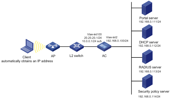
Configuration prerequisites and guidelines
Configure IP addresses for the AC and servers as shown in Figure 22, and make sure the client, AC, and servers have IP connectivity between each other.
· Configure the RADIUS server properly to provide authentication and accounting services for users.
· Configure a public address pool (20.20.20.0/24, in this example) and a private address pool (10.0.0.0/24, in this example) on the DHCP server. (Details not shown.)
· Configure the AC as a DHCP relay agent and configure a primary IP address (a public IP address) and a secondary IP address (a private IP address) for the portal-enabled interface. For DHCP relay configuration information, see Layer 3—IP Services Configuration Guide.
Configuration procedure
1. Configure a RADIUS scheme on the AC:
# Create a RADIUS scheme named rs1 and enter its view.
<AC> system-view
[AC] radius scheme rs1
# Set the server type for the RADIUS scheme. When using the IMC server, set the server type to extended.
[AC-radius-rs1] server-type extended
# Specify the primary authentication server and primary accounting server, and configure the keys for communication with the servers.
[AC-radius-rs1] primary authentication 192.168.0.113
[AC-radius-rs1] primary accounting 192.168.0.113
[AC-radius-rs1] key accounting simple radius
[AC-radius-rs1] key authentication simple radius
[AC-radius-rs1] user-name-format without-domain
# Configure the IP address of the security policy server.
[AC-radius-rs1] security-policy-server 192.168.0.114
[AC-radius-rs1] quit
2. Configure an authentication domain on the AC:
# Create an ISP domain named dm1 and enter its view.
[AC] domain dm1
# Configure the ISP domain to use RADIUS scheme rs1.
[AC-isp-dm1] authentication portal radius-scheme rs1
[AC-isp-dm1] authorization portal radius-scheme rs1
[AC-isp-dm1] accounting portal radius-scheme rs1
[AC-isp-dm1] quit
3. On the AC, configure the ACL (ACL 3000) for resources on subnet 192.168.0.0/24 and the ACL (ACL 3001) for Internet resources.
[AC] acl number 3000
[AC-acl-adv-3000] rule permit ip destination 192.168.0.0 0.0.0.255
[AC-acl-adv-3000] quit
[AC] acl number 3001
[AC-acl-adv-3001] rule permit ip
[AC-acl-adv-3001] quit
Make sure you specify ACL 3000 as the isolation ACL and ACL 3001 as the security ACL on the security policy server.
4. Configure extended portal authentication on the AC:
# Configure the portal server as follows:
¡ Name: newpt
¡ IP address: 192.168.0.111
¡ Key: portal (in plaintext)
¡ Port number: 50100
¡ URL: http://192.168.0.111:8080/portal
[AC] portal server newpt ip 192.168.0.111 key simple portal port 50100 url http://192.168.0.111:8080/portal
# Configure a portal-free rule to allow access from the AC to any destinations without portal authentication. This configuration is required only on the AC module.
[AC] portal free-rule 0 source interface bridge-aggregation 1 destination any
# Configure the AC as a DHCP relay agent, and enable the invalid address check function.
[AC] dhcp enable
[AC] dhcp relay server-group 0 ip 192.168.0.112
[AC] interface vlan-interface 100
[AC–Vlan-interface100] ip address 20.20.20.1 255.255.255.0
[AC–Vlan-interface100] ip address 10.0.0.1 255.255.255.0 sub
[AC-Vlan-interface100] dhcp select relay
[AC-Vlan-interface100] dhcp relay server-select 0
[AC-Vlan-interface100] dhcp relay address-check enable
# On the interface connected to the client, specify the authentication domain dm1 for portal users and enable portal authentication.
[AC–Vlan-interface100] portal domain dm1
[AC–Vlan-interface100] portal server newpt method redhcp
[AC–Vlan-interface100] quit
Configuring portal stateful failover
Network requirements
As shown in Figure 23, a failover link is present between AC 1 and AC 2. Both AC 1 and AC 2 support portal authentication. Configure stateful failover between AC 1 and AC 2 to support portal service backup and use VRRP to implement traffic switchover between the ACs.
· When AC 1 operates correctly, Host accesses AC 1 for portal authentication before accessing the Internet. When AC 1 fails, Host accesses the Internet through AC 2. The VRRP uplink/downlink detection mechanism is used to ensure non-stop traffic forwarding.
· Use the RADIUS server as the authentication/accounting server. In this example, Server takes the responsibilities of the portal server and the RADIUS server.
· AC 1 and AC 2 use the failover link to transmit stateful failover related packets and specify VLAN 8 on the ACs as the VLAN dedicated for stateful failover related packets.
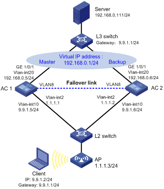
Configuration prerequisites and guidelines
Configure IP addresses for the client, server, and ACs as shown in Figure 23 and make sure they have IP connectivity between each other.
On the authentications server, specify the access device's IP address as the virtual IP address of the VRRP group. For more information about VRRP, see High Availability Configuration Guide.
For information about stateful failover configuration, see High Availability Configuration Guide.
You must use consistent device roles for AC stateful failover and VRRP. If you use an AC as the master for stateful failover, use the AC as the master in a VRRP group, too. Otherwise, in local portal authentication, the access device cannot push authentication pages according to the SSID. If your network cannot meet the requirement, for example, the two ACs are configured for load balancing, related portal-free rules should be configured.
Configuring the portal server on IMC 3.60
This section uses IMC PLAT 3.20-R2602P13 and IMC UAM 3.60-E6301.
1. Configure the portal server:
a. Log in to IMC and click the Service tab.
b. From the navigation tree, select Portal Service Management > Server to enter the portal server configuration page, as shown in Figure 24.
c. Configure the portal server parameters as needed.
This example uses the default values.
d. Click OK.
Figure 24 Portal server configuration

2. Configure an IP address group:
a. From the navigation tree, select Portal Service Management > IP Group to enter the portal IP address group configuration page.
b. Click Add to enter the page shown in Figure 25.
c. Enter the IP group name.
d. Enter the start IP address and end IP address of the IP group. Make sure the client's IP address is in the IP group.
e. Select a service group.
By default, the group Ungrouped is used.
f. Select the IP group type Normal.
g. Click OK.
Figure 25 Adding an IP address group
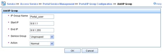
3. Add a portal device:
a. From the navigation tree, select Portal Service Management > Device to enter the portal device configuration page.
b. Click Add to enter the page shown in Figure 26.
c. Enter the device name AC.
d. Specify the virtual IP address of the VRRP group (the portal NAS-IP address specified on the ACs).
e. Enter the key, which must be the same as that configured on the ACs.
f. Set whether to enable IP address reallocation.
This example uses direct portal authentication. Therefore, select No from the Reallocate IP list.
g. Set whether to support the portal server heartbeat and user heartbeat functions.
In this example, select No for both Support Server Heartbeat and Support User Heartbeat.
h. Click OK.
Figure 26 Adding a portal device
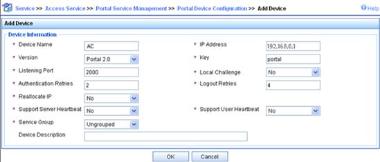
4. Associate the portal device with the IP address group:
a. As shown in Figure 27, click the icon in the Port Group Information Management column of device AC to enter the port group configuration page.
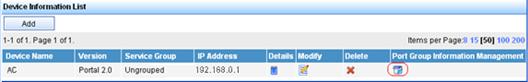
b. On the port group configuration page, click Add to enter the page shown in Figure 28. Perform the following configurations.
c. Enter the port group name.
d. Select the configured IP address group from the IP Group list.
e. The client's IP address must be within this IP address group.
Use the default settings for other parameters.
f. Click OK.

5. From the navigation tree, select Service Parameters > Validate System Configuration to validate the configurations.
Configuring portal server on IMC 5.0
This section uses IMC PLAT 5.0 (E0101) and IMC UAM 5.0 (E0101).
1. Configure the portal server:
a. Log in to IMC and click the Service tab.
b. From the navigation tree, select User Access Manager > Portal Service Management > Server to enter the portal server configuration page, as shown in Figure 29.
c. Configure the portal server parameters as needed. This example uses the default settings.
d. Click OK.
Figure 29 Portal server configuration

2. Configure the IP address group:
a. From the navigation tree, select User Access Manager > Portal Service Management > IP Group to enter the portal IP address group configuration page.
b. Click Add to enter the page shown in Figure 30.
c. Enter the IP group name.
d. Enter the start IP address and end IP address of the IP group.
Make sure that the client's IP address is in the IP group.
e. Select a service group.
By default, the group Ungrouped is used.
f. Select the IP group type Normal.
g. Click OK.
Figure 30 Adding an IP address group
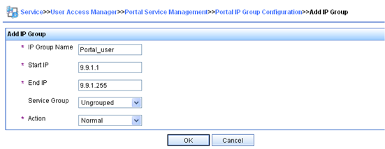
3. Add a portal device:
a. From the navigation tree, select User Access Manager > Portal Service Management > Device to enter the portal device configuration page.
b. Click Add to enter the page shown in Figure 31.
c. Enter the device name AC.
d. Enter the virtual IP address of the VRRP group that holds the portal-enabled interface.
e. Enter the key, which must be the same as that configured on the ACs.
f. Set whether to enable IP address reallocation.
This example uses direct portal authentication. Therefore, select No from the Reallocate IP list.
g. Set whether to support the portal server heartbeat and user heartbeat functions.
In this example, select No for both Support Server Heartbeat and Support User Heartbeat.
h. Click OK.
Figure 31 Adding a portal device
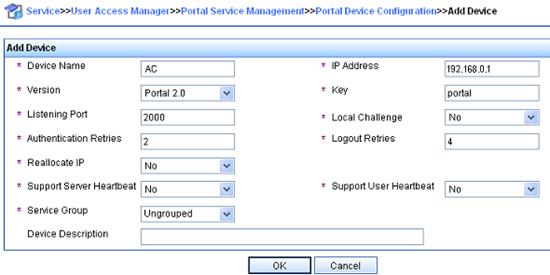
4. Associate the portal device with the IP address group:
a. As shown in Figure 32, click the icon in the Port Group Information Management column of device AC to enter the port group configuration page.
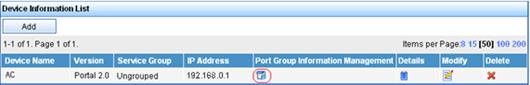
b. On the port group configuration page, click Add to enter the page shown in Figure 33. Perform the following configurations.
c. Enter the port group name.
d. Select the configured IP address group.
The client's IP address must be within this IP address group.
e. Use the default settings for other parameters.
f. Click OK.
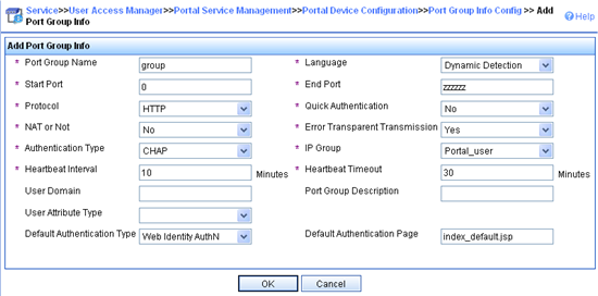
5. From the navigation tree, select User Access Manager > User Access Manager > Service Parameters > Validate System Configuration to validate the configurations.
Configuring AC 1
1. Configure VRRP:
# Create a VRRP group, and configure the virtual IP address of the VRRP group as 192.168.0.1.
<AC1> system-view
[AC1] interface vlan-interface 20
[AC1–Vlan-interface20] vrrp vrid 1 virtual-ip 192.168.0.1
# Set the priority of VLAN-interface 20 in the VRRP group to 200.
[AC1–Vlan-interface20] vrrp vrid 1 priority 200
# On VLAN-interface 20, configure the interface to be tracked as VLAN-interface 10 and reduce the priority of VLAN-interface 20 in the VRRP group by 150 when the interface state of VLAN-interface 10 becomes Down or Removed.
[AC1–Vlan-interface20] vrrp vrid 1 track interface vlan-interface10 reduced 150
[AC1–Vlan-interface20] quit
2. Configure a RADIUS scheme:
# Create RADIUS scheme rs1 and enter its view.
[AC1] radius scheme rs1
# Configure the server type for the RADIUS scheme. When using the IMC server, you must configure the RADIUS server type as extended.
[AC1-radius-rs1] server-type extended
# Specify the primary authentication server and primary accounting server, and configure the keys for communication with the servers.
[AC1-radius-rs1] primary authentication 192.168.0.111
[AC1-radius-rs1] primary accounting 192.168.0.111
[AC1-radius-rs1] key authentication simple expert
[AC1-radius-rs1] key accounting simple expert
# Configure the access device to not carry the ISP domain name in the username sent to the RADIUS server. (Optional, configure the username format as needed.)
[AC1-radius-rs1] user-name-format without-domain
[AC1-radius-rs1] quit
3. Configure an authentication domain:
# Create ISP domain dm1 and enter its view.
[AC1] domain dm1
# Configure AAA methods for the ISP domain.
[AC1-isp-dm1] authentication portal radius-scheme rs1
[AC1-isp-dm1] authorization portal radius-scheme rs1
[AC1-isp-dm1] accounting portal radius-scheme rs1
[AC1-isp-dm1] quit
4. Enable portal authentication on the interface connecting the host:
# Configure a portal server on AC 1. Make sure the IP address, port number and URL match those of the actual portal server.
[AC1] portal server newpt ip 192.168.0.111 key simple portal port 50100 url http://192.168.0.111:8080/portal
# Configure a portal-free rule on AC 1, allowing packets from AC 2 to pass through without portal authentication. This configuration is required only when the roles (master/backup) of the ACs for stateful failover are different from those for VRRP.
[AC1] portal free-rule 0 source interface bridge-aggregation 1 destination any
# On the interface connected to the client, specify the authentication domain dm1 for portal users and enable portal authentication.
[AC1] interface vlan-interface 10
[AC1–Vlan-interface10] portal domain dm1
[AC1–Vlan-interface10] portal server newpt method direct
# Specify the source IP address of outgoing portal packets as 192.168.0.1, the virtual IP address of the VRRP group.
[AC1–Vlan-interface10] portal nas-ip 192.168.0.1
5. Configure portal stateful failover:
# Assign interface VLAN-interface 10 to portal group 1.
[AC1–Vlan-interface10] portal backup-group 1
[AC1–Vlan-interface10] quit
# Set the device ID for AC 1 in stateful failover mode to 1.
[AC1] nas device-id 1
# Specify the source IP address of outgoing RADIUS packets as 192.168.0.1, the virtual IP address of the VRRP group.
[AC1] radius nas-ip 192.168.0.1
|
|
NOTE: Make sure you add the access device with IP address 192.168.0.1 on the RADIUS server. |
6. Configure the WLAN service:
# Specify the backup AC address.
[AC1] wlan backup-ac ip 1.1.1.2
# Enable hot backup.
[AC1] hot-backup enable
# Configure VLAN 8 as the VLAN for AC hot backup.
[AC1] hot-backup vlan 8
[AC1] quit
# Create interface WLAN-ESS 1, and add it to VLAN 10.
[AC1] interface wlan-ess 1
[AC1-WLAN-ESS1] port link-type hybrid
[AC1-WLAN-ESS1] port hybrid vlan 10 untagged
[AC1-WLAN-ESS1] port hybrid pvid vlan 10
[AC1-WLAN-ESS1] quit
# Configure a WLAN service template, and bind the WLAN service template with interface WLAN-ESS 1.
[AC1] wlan service-template 1 clear
[AC1-wlan-st-1] ssid abc
[AC1-wlan-st-1] bind wlan-ess 1
[AC1-wlan-st-1] service-template enable
[AC1-wlan-st-1] quit
# Configure AP on AC 1. (Set the access priority of AP to 7. A higher value represents a higher priority. The default priority value is 4.)
[AC1] wlan ap ap1 model WA3628i-AGN
[AC1-wlan-ap-ap1] serial-id 210235A29G007C000020
[AC1-wlan-ap-ap1] priority level 7
[AC1-wlan-ap-ap1] radio 1
[AC1-wlan-ap-ap1-radio-1] service-template 1
[AC1-wlan-ap-ap1-radio-1] radio enable
[AC1-wlan-ap-ap1-radio-1] quit
[AC1-wlan-ap-ap1] quit
7. Configure the stateful failover function:
# Configure the VLAN for stateful failover as VLAN 8.
[AC1] dhbk vlan 8
# Enable stateful failover and configure it to support the symmetric path.
[AC1] dhbk enable backup-type symmetric-path
Configuring AC 2
1. Configure VRRP:
# Create a VRRP group, and configure the virtual IP address of the VRRP group as 192.168.0.1.
[AC2] system-view
[AC2] interface vlan-interface 20
[AC2–Vlan-interface20] vrrp vrid 1 virtual-ip 192.168.0.1
# Set the priority of VLAN-interface 20 in the VRRP group to 150.
[AC2–Vlan-interface20] vrrp vrid 1 priority 150
[AC2–Vlan-interface20] quit
2. Configure a RADIUS scheme:
# Create RADIUS scheme rs1 and enter its view.
[AC2] radius scheme rs1
# Configure the server type for the RADIUS scheme. When using the IMC server, you must configure the RADIUS server type as extended.
[AC2-radius-rs1] server-type extended
# Specify the primary authentication server and primary accounting server, and configure the keys for communication with the servers.
[AC2-radius-rs1] primary authentication 192.168.0.111
[AC2-radius-rs1] primary accounting 192.168.0.111
[AC2-radius-rs1] key authentication simple expert
[AC2-radius-rs1] key accounting simple expert
# Configure the access device to not carry the ISP domain name in the username sent to the RADIUS server. (Optional. Configure the username format as needed.)
[AC2-radius-rs1] user-name-format without-domain
[AC2-radius-rs1] quit
3. Configure an authentication domain:
# Create ISP domain dm1 and enter its view.
[AC2] domain dm1
# Configure AAA methods for the ISP domain.
[AC2-isp-dm1] authentication portal radius-scheme rs1
[AC2-isp-dm1] authorization portal radius-scheme rs1
[AC2-isp-dm1] accounting portal radius-scheme rs1
[AC2-isp-dm1] quit
4. Enable portal authentication on the interface connecting the host:
# Configure the portal server as needed.
[AC2] portal server newpt ip 192.168.0.111 key simple portal port 50100 url http://192.168.0.111:8080/portal
# Configure a portal-free rule on AC 2, allowing packets from AC 1 to pass through without portal authentication. This configuration is required only when the roles (master/backup) of the ACs for stateful failover are different from those for VRRP.
[AC2] portal free-rule 0 source interface bridge-aggregation 1 destination any
# On the interface connected to the client, specify the authentication domain dm1 for portal users and enable portal authentication.
[AC2] interface vlan-interface 10
[AC2-Vlan-interface10] portal domain dm1
[AC2–Vlan-interface10] portal server newpt method direct
# Specify the source IP address of outgoing portal packets as 192.168.0.1, the virtual IP address of the VRRP group.
[AC2–Vlan-interface10] portal nas-ip 192.168.0.1
5. Configure portal stateful failover:
# Assign interface VLAN-interface 10 to portal group 1.
[AC2–Vlan-interface10] portal backup-group 1
[AC2–Vlan-interface10] quit
# Set the ID of the device in the stateful failover mode to 2.
[AC2] nas device-id 2
# Specify the source IP address of outgoing RADIUS packets as 192.168.0.1, the virtual IP address of the VRRP group.
[AC2] radius nas-backup-ip 192.168.0.1
|
|
NOTE: Make sure that you have added the access device with IP address 192.168.0.1 on the RADIUS server. |
6. Configure the WLAN service:
# Specify the backup AC address.
[AC2] wlan backup-ac ip 1.1.1.1
# Enable hot backup.
[AC2] hot-backup enable
# Configure VLAN 8 as the VLAN for AC hot backup.
[AC2] hot-backup vlan 8
[AC2] quit
# Create interface WLAN-ESS 1, and add it to VLAN 10.
[AC2] interface wlan-ess 1
[AC2-WLAN-ESS1] port link-type hybrid
[AC2-WLAN-ESS1] port hybrid vlan 10 untagged
[AC2-WLAN-ESS1] port hybrid pvid vlan 10
[AC2-WLAN-ESS1] quit
# Configure a WLAN service template, and bind the WLAN service template with interface WLAN-ESS 1.
[AC2] wlan service-template 1 clear
[AC2-wlan-st-1] ssid abc
[AC2-wlan-st-1] bind wlan-ess 1
[AC2-wlan-st-1] service-template enable
[AC2-wlan-st-1] quit
# Configure AP on AC 2, using the default access priority of 4 for the AP.
[AC2] wlan ap ap1 model WA3628i-AGN
[AC2-wlan-ap-ap1] serial-id 210235A29G007C000020
[AC2-wlan-ap-ap1] radio 1
[AC2-wlan-ap-ap1-radio-1] service-template 1
[AC2-wlan-ap-ap1-radio-1] radio enable
[AC2-wlan-ap-ap1-radio-1] quit
[AC2-wlan-ap-ap1] quit
7. Configure stateful failover:
# Configure the VLAN for stateful failover as VLAN 8.
[AC2] dhbk vlan 8
# Enable stateful failover and configure it to support the symmetric path.
[AC2] dhbk enable backup-type symmetric-path
Verifying the configuration
# After the client logs in through AC 1, display the user authentication information by using the display portal user command on AC 1 and AC 2, respectively.
[AC1] display portal user all
Index:3
State:ONLINE
SubState:NONE
ACL:NONE
Work-mode: primary
MAC IP Vlan Interface
---------------------------------------------------------------------
000d-88f8-0eac 9.9.1.2 10 Vlan-interface10
Total 1 user(s) matched, 1 listed.
[AC2] display portal user all
Index:2
State:ONLINE
SubState:NONE
ACL:NONE
Work-mode: secondary
MAC IP Vlan Interface
---------------------------------------------------------------------
000d-88f8-0eac 9.9.1.2 10 Vlan-interface10
Total 1 user(s) matched, 1 listed.
The output shows that the portal information of the client is stored on both AC 1 and AC 2. The user mode is primary on AC 1 and secondary on AC 2, indicating that the client logged in from AC 1 and the client's authentication information has been synchronized to AC 2.
Configuring portal server detection and portal user information synchronization
Network requirements
As shown in Figure 34, a wireless client (in VLAN 10) is connected to the access device (AC) and must pass portal authentication to access the Internet. Use a RADIUS server as the authentication/accounting server.
Detailed requirements are as follows:
· Configure a public IP address for the client or configure the client to obtain a public IP address from the DHCP server. Before passing portal authentication, the client can access only the portal server. After passing portal authentication, the client can access the Internet.
· The access device (AC) can detect whether the portal server is reachable and send trap messages upon state changes. When the portal server is unreachable due to, for example, a connection failure, network device failure, or portal server failure, the access device can disable portal authentication, allowing users to access the Internet without authentication.
· The access device can synchronize portal user information with the portal server periodically.
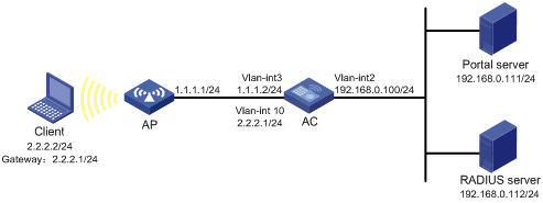
Configuration considerations
· Configure the portal server and enable portal server heartbeat function and the portal user heartbeat function.
· Configure the RADIUS server to implement authentication and accounting.
· Configure direct portal authentication on interface VLAN-interface 10, which is connected to the client.
· Configure the portal server detection function on the access device, so that the access device can detect the status of the portal server by cooperating with the portal server heartbeat function.
· Configure the portal user information synchronization function, so that the access device can synchronize portal user information with the portal server by cooperating with the portal user heartbeat function.
Configuration prerequisites
Configure IP addresses for the client, AP, AC, and servers as shown in Figure 34, and make sure they have IP connectivity between each other.
Configure the RADIUS server properly to provide authentication and accounting services for users.
Configuring the portal server on IMC 3.60
This example assumes that the portal server runs on IMC PLAT 3.20-R2606P13 and IMC UAM 3.60-E6301.
1. Configure the portal server:
a. Log in to IMC and click the Service tab.
b. From the navigation tree, select Portal Service Management > Server to enter the portal server configuration page, as shown in Figure 35.
c. Configure the portal server heartbeat interval and user heartbeat interval.
d. Use default values for other parameters.
e. Click OK.
Figure 35 Portal server configuration
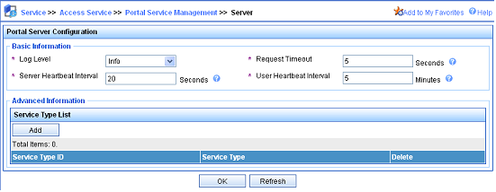
2. Configure the IP address group:
a. From the navigation tree, select Portal Service Management > IP Group to enter the portal IP address group configuration page.
b. Click Add to enter the page shown in Figure 36.
c. Enter the IP group name.
d. Enter the start IP address and end IP address of the IP group.
Make sure that the client's IP address is in the IP group.
e. Select a service group.
By default, the group Ungrouped is used.
f. Select the IP group type Normal.
g. Click OK.
Figure 36 Adding an IP address group
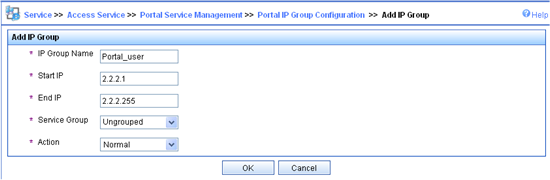
3. Add a portal device:
a. From the navigation tree, select Portal Service Management > Device to enter the portal device configuration page.
b. Click Add to enter the page shown in Figure 37.
c. Enter the device name AC.
d. Enter the IP address of AC's interface connected to the user.
e. Enter the key, which must be the same as that configured on the AC.
f. Set whether to enable IP address reallocation. Direct portal authentication is used in this example, and therefore select No from the Reallocate IP list.
g. Select Yes for both Support Server Heartbeat and Support User Heartbeat.
h. Click OK.
Figure 37 Adding a portal device
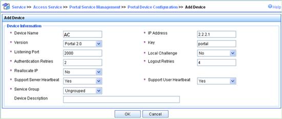
4. Associate the portal device with the IP address group:
a. As shown in Figure 38, click the icon in the Port Group Information Management column of device AC to enter the port group configuration page.
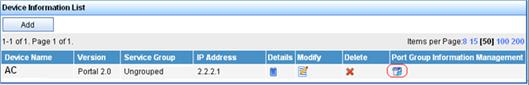
b. On the port group configuration page, click Add to enter the page shown in Figure 39. Perform the following configurations:
c. Enter the port group name.
d. Select the configured IP address group. The client's IP address must be within this IP address group.
e. Use the default settings for other parameters.
f. Click OK.
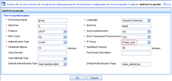
5. From the navigation tree, select Service Parameters > Validate System Configuration to validate the configurations.
Configuring the portal server on IMC 5.0
This section uses IMC PLAT 5.0(E0101) and IMC UAM 5.0(E0101).
1. Configure the portal server:
a. Log in to the IMC management platform and click the Service tab.
b. From the navigation tree, select User Access Manager > Portal Service Management > Server to enter the portal server configuration page, as shown in Figure 40.
c. Configure the portal server heartbeat interval and user heartbeat interval.
d. Use default values for other parameters.
e. Click OK.
Figure 40 Portal server configuration

2. Configure the IP address group:
a. From the navigation tree, select User Access Manager > Portal Service Management > IP Group to enter the portal IP address group configuration page.
b. Click Add to enter the page shown in Figure 41.
c. Enter the IP group name.
d. Enter the start IP address and end IP address of the IP group. Make sure the client's IP address is in the IP group.
e. Select a service group.
By default, the group Ungrouped is used.
f. Select the IP group type Normal.
g. Click OK.
Figure 41 Adding an IP address group
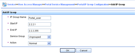
3. Add a portal device:
a. From the navigation tree, select User Access Manager > Portal Service Management > Device to enter the portal device configuration page.
b. Click Add to enter the page shown in Figure 42.
c. Enter the device name AC.
d. Enter the IP address of the AC's interface connected to the user.
e. Enter the key, which must be the same as that configured on the AC.
f. Set whether to enable IP address reallocation.
This example uses direct portal authentication. Therefore, select No from the Reallocate IP list.
g. Select Yes for both Support Server Heartbeat and Support User Heartbeat.
h. Click OK.
Figure 42 Adding a portal device
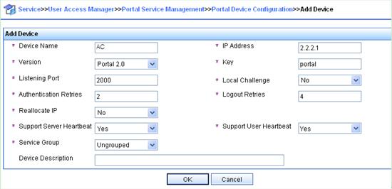
4. Associate the portal device with the IP address group:
a. As shown in Figure 43, click the icon in the Port Group Information Management column of device AC to enter the port group configuration page.
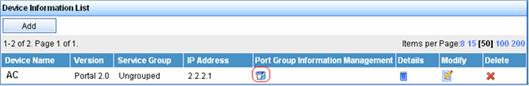
b. On the port group configuration page, click Add to enter the page shown in Figure 44. Perform the following configurations:
c. Enter the port group name.
d. Select the configured IP address group. The IP address used by the user to access the network must be within this IP address group.
e. Use the default settings for other parameters.
f. Click OK.
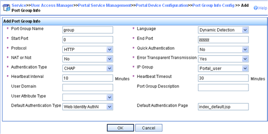
5. From the navigation tree, select User Access Manager > Service Parameters > Validate System Configuration to validate the configurations.
Configuring the AC
1. Configure a RADIUS scheme:
# Create RADIUS scheme rs1 and enter its view.
<AC> system-view
[AC] radius scheme rs1
# Configure the server type for the RADIUS scheme. When using the IMC server, you must configure the RADIUS server type as extended.
[AC-radius-rs1] server-type extended
# Specify the primary authentication server and primary accounting server, and configure the keys for communication with the servers.
[AC-radius-rs1] primary authentication 192.168.0.112
[AC-radius-rs1] primary accounting 192.168.0.112
[AC-radius-rs1] key authentication simple radius
[AC-radius-rs1] key accounting simple radius
# Configure the access device to not carry the ISP domain name in the username sent to the RADIUS server.
[AC-radius-rs1] user-name-format without-domain
[AC-radius-rs1] quit
2. Configure an authentication domain:
# Create ISP domain dm1 and enter its view.
[AC] domain dm1
# Configure AAA methods for the ISP domain.
[AC-isp-dm1] authentication portal radius-scheme rs1
[AC-isp-dm1] authorization portal radius-scheme rs1
[AC-isp-dm1] accounting portal radius-scheme rs1
[AC-isp-dm1] quit
3. Configure portal authentication:
# Configure a portal server on the AC, making sure the IP address, port number and URL match those of the actual portal server.
[AC] portal server newpt ip 192.168.0.111 key simple portal port 50100 url http://192.168.0.111:8080/portal
# Configure a portal-free rule to allow access from the AC to any destinations without portal authentication. This configuration is required only on the AC module.
[AC] portal free-rule 0 source interface bridge-aggregation 1 destination any
# On the interface connected to the client, specify the authentication domain dm1 for portal users and enable portal authentication.
[AC] interface vlan-interface 10
[AC–Vlan-interface10] portal domain dm1
[AC–Vlan-interface10] portal server newpt method direct
[AC–Vlan-interface10] quit
4. Configure the portal server detection function:
# Configure the access device to detect portal server newpt, specifying the detection method as portal heartbeat probe, setting the server probe interval to 40 seconds, and specifying the access device to send a server unreachable trap message and disable portal authentication to permit unauthenticated portal users if two consecutive probes fail.
[AC] portal server newpt server-detect method portal-heartbeat action trap permit-all interval 40 retry 2
|
|
NOTE: The product of interval and retry must be greater than or equal to the portal server heartbeat interval, and H3C recommends configuring the interval as a value greater than the portal server heartbeat interval configured on the portal server. |
5. Configure portal user synchronization:
# Configure the access device to synchronize portal user information with portal server newpt, setting the synchronization probe interval to 600 seconds, and specifying the access device to log off users if the users do not appear in the user synchronization packets sent from the server in two consecutive probe intervals.
[AC] portal server newpt user-sync interval 600 retry 2
|
|
NOTE: The product of interval and retry must be greater than or equal to the portal user heartbeat interval, and H3C recommends configuring the interval as a value greater than the portal user heartbeat interval configured on the portal server. |
Verifying the configuration
Use the following command to view information about the portal server.
<AC> display portal server newpt
Portal server:
1)newpt:
IP : 192.168.0.111
Key : ******
Port : 50100
URL : http://192.168.0.111:8080/portal
Status : Up
The Up state of the portal server indicates that the portal server is reachable. If the AC detects that the portal server is unreachable, you can see the portal server status is Down in the output, and the AC generates a server unreachable trap "portal server newpt lost," and disables portal authentication on the access interface, so the client can access the external network without authentication.
Configuring direct portal authentication using local portal server
Network requirements
As shown in Figure 45, a wireless client is connected to the network through the AP. The client belongs to VLAN 2 and the AP belongs to VLAN 3. The client must pass direct portal authentication to access Internet resources. Before authentication, the client can access only the local portal server.
The AC (access device) uses the local portal server that runs HTTPS to perform direct portal authentication for users. The local portal server can push customized pages according to the SSID of the user logon interface.
Use a RADIUS server as the authentication/accounting server.
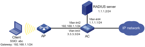
Configuration prerequisites and guidelines
· Configure IP addresses for the client, AC, and server as shown in Figure 45, and make sure they have IP connectivity between each other.
· Configure the RADIUS server properly to provide authentication and accounting services for users.
· Complete the PKI domain configuration, and get the local certificate and the CA certificate. For more configuration information, see "Configuring PKI."
· Configure the SSL server policy access-policy. For more configuration information, see "Configuring SSL."
· Edit the authentication page files to be bound with the client SSID.
· Do not configure the wireless client and the AP to be in the same subnet. Otherwise, after portal authentication is enabled for the subnet, the AP cannot establish a connection with the AC.
Configuration procedure
1. Configure a RADIUS scheme on the AC:
# Create a RADIUS scheme named rs1 and enter its view.
<AC> system-view
[AC] radius scheme rs1
# Set the server type for the RADIUS scheme. When using the IMC server, set the server type to extended.
[AC-radius-rs1] server-type extended
# Specify the primary authentication server and primary accounting server, and configure the keys for communication with the servers.
[AC-radius-rs1] primary authentication 1.1.1.2
[AC-radius-rs1] primary accounting 1.1.1.2
[AC-radius-rs1] key authentication simple radius
[AC-radius-rs1] key accounting simple radius
# Specify that the ISP domain name should not be included in the username sent to the RADIUS server.
[AC-radius-rs1] user-name-format without-domain
[AC-radius-rs1] quit
2. Configure an authentication domain on the AC:
# Create an ISP domain named dm1 and enter its view.
[AC] domain dm1
# Configure the ISP domain to use RADIUS scheme rs1.
[AC-isp-dm1] authentication portal radius-scheme rs1
[AC-isp-dm1] authorization portal radius-scheme rs1
[AC-isp-dm1] accounting portal radius-scheme rs1
[AC-isp-dm1] quit
3. Configure the WLAN service on the AC:
# Create interface WLAN-ESS 1 and add it to VLAN 2.
[AC] interface wlan-ess 1
[AC-WLAN-ESS1] port link-type hybrid
[AC-WLAN-ESS1] port hybrid vlan 2 untagged
[AC-WLAN-ESS1] port hybrid pvid vlan 2
[AC-WLAN-ESS1] quit
# Configure a WLAN service template, and bind the WLAN service template with the WLAN-ESS interface.
[AC] wlan service-template 1 clear
[AC-wlan-st-1] ssid abc
[AC-wlan-st-1] bind wlan-ess 1
[AC-wlan-st-1] authentication-method open-system
[AC-wlan-st-1] service-template enable
[AC-wlan-st-1] quit
# Configure AP on the AC.
[AC] wlan ap ap1 model WA3628i-AGN
[AC-wlan-ap-ap1] serial-id 210235A29G007C000020
[AC-wlan-ap-ap1] radio 1 type dot11an
[AC-wlan-ap-ap1-radio-1] service-template 1
[AC-wlan-ap-ap1-radio-1] radio enable
[AC-wlan-ap-ap1-radio-1] quit
[AC-wlan-ap-ap1] quit
4. Configure portal authentication on the AC:
# Configure the local portal server to support HTTPS and reference the configured SSL server policy access-policy.
[AC] portal local-server https server-policy access-policy
# Bind client SSID abc with the customized authentication page file ssid1.zip, which is saved in directory flash:/portal/ of the AC. This configuration is optional. If you do not configure the binding, the AC pushes the system default authentication pages for users.
[AC] portal local-server bind ssid abc file ssid1.zip
# Configure the local portal server name as newpt and IP address as 192.168.1.1. Other parameters do not need to be configured.
[AC] portal server newpt ip 192.168.1.1
# On VLAN-interface 2, the interface connected to the client, specify the authentication domain dm1 and portal server newpt for portal users and enable direct portal authentication.
[AC] interface vlan-interface 2
[AC–Vlan-interface2] portal domain dm1
[AC–Vlan-interface2] portal server newpt method direct
[AC–Vlan-interface2] quit
Verifying the configuration
# Connect the wireless client to the wireless network whose SSID is abc. (Details not shown.)
# On the client, access subnet 1.1.1.0/24 by using a Web browser.
# Verify that you are redirected to the login page https://192.168.1.1/portal/logon.htm.
# Enter the correct username and password on the page. You will receive an authentication success notification.
# Use the display portal user command on the AC to display information about portal users. (Details not shown.)
Configuring portal stateful failover with local portal servers
Network requirements
As shown in Figure 46, a failover link is present between AC 1 and AC 2. Both AC 1 and AC 2 support portal authentication. Configure stateful failover between AC 1 and AC 2 to support portal service backup and use VRRP to implement traffic switchover between the ACs.
More specifically, the following occurs:
· When AC 1 operates correctly, Client accesses AC 1 for portal authentication before accessing the Internet. When AC 1 fails, Client accesses the Internet through AC 2. Use VRRP uplink/downlink detection mechanism to ensure non-stop traffic forwarding.
· Use the RADIUS server as the authentication/accounting server.
· Use local portal servers on the ACs.
· AC 1 and AC 2 use the failover link to transmit stateful failover related packets. Specify VLAN 10 on the ACs as the VLAN dedicated for stateful failover related packets.
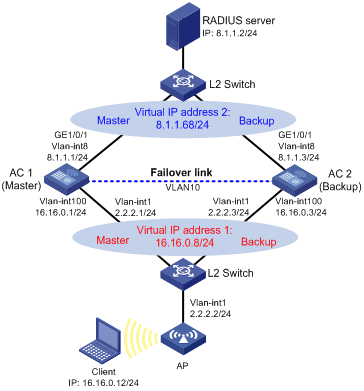
Configuration prerequisites and guidelines
· Configure IP addresses for the server, client, switches, and ACs and make sure they have IP connectivity between each other.
· Make sure the client can access the authentication server through AC 1 and AC 2, respectively.
· Configure VRRP group 1 and VRRP group 2 to implement backup for downstream and upstream links respectively. For more information about VRRP, see High Availability Configuration Guide.
· On the RADIUS server, specify the access device's IP address as the virtual IP address of VRRP group 2.
· For more information about stateful failover, see High Availability Configuration Guide.
· You must use consistent device roles for AC stateful failover and VRRP. If you use an AC as the master for stateful failover, use the AC as the master in a VRRP group, too. Otherwise, in local portal authentication, the access device cannot push the authentication page according to the SSID. If your network cannot meet the requirement, for example, the two ACs are configured for load balancing, related portal-free rules should be configured.
Configuring AC 1
1. Configure VRRP:
# Create VRRP group 1, and configure the virtual IP address of VRRP group 1 as 16.16.0.8.
<AC1> system-view
[AC1] interface vlan-interface 100
[AC1–Vlan-interface100] vrrp vrid 1 virtual-ip 16.16.0.8
# Set the priority of VLAN-interface 100 in VRRP group 1 to 200.
[AC1–Vlan-interface100] vrrp vrid 1 priority 200
# On VLAN-interface 100, configure the interface to be tracked as VLAN-interface 8 and reduce the priority of VLAN-interface 100 in VRRP group 1 by 120 when the interface state of VLAN-interface 8 becomes Down or Removed.
[AC1–Vlan-interface100] vrrp vrid 1 track interface vlan-interface8 reduced 120
[AC1–Vlan-interface100] quit
# Create VRRP group 2, and configure the virtual IP address of VRRP group 2 as 8.1.1.68.
[AC1] interface vlan-interface 8
[AC1–Vlan-interface8] vrrp vrid 2 virtual-ip 8.1.1.68
# Set the priority of VLAN-interface 8 in VRRP group 2 to 200.
[AC1–Vlan-interface8] vrrp vrid 2 priority 200
# On VLAN-interface 8, configure the interface to be tracked as VLAN-interface 100 and reduce the priority of VLAN-interface 8 in VRRP group 2 by 120 when the interface state of VLAN-interface 100 becomes Down or Removed.
[AC1–Vlan-interface8] vrrp vrid 2 track interface vlan-interface100 reduced 120
[AC1–Vlan-interface8] quit
2. Configure a RADIUS scheme:
# Create RADIUS scheme rs1 and enter its view.
[AC1] radius scheme rs1
# Configure the server type for the RADIUS scheme. When using the IMC server, configure the RADIUS server type as extended.
[AC1-radius-rs1] server-type extended
# Specify the primary authentication server and primary accounting server, and configure the keys for communication with the servers.
[AC1-radius-rs1] primary authentication 8.1.1.2
[AC1-radius-rs1] primary accounting 8.1.1.2
[AC1-radius-rs1] key authentication simple expert
[AC1-radius-rs1] key accounting simple expert
# Configure the scheme to remove the ISP domain name in the username sent to the RADIUS server. (By default, the ISP domain name is carried in the username. Configure the username format as needed.)
[AC1-radius-rs1] user-name-format without-domain
[AC1-radius-rs1] quit
3. Configure an authentication domain:
# Create ISP domain dm1 and enter its view.
[AC1] domain dm1
# Configure AAA methods for the ISP domain.
[AC1-isp-dm1] authentication portal radius-scheme rs1
[AC1-isp-dm1] authorization portal radius-scheme rs1
[AC1-isp-dm1] accounting portal radius-scheme rs1
[AC1-isp-dm1] quit
4. Enable portal authentication on the interface connected to the client:
# Configure the portal server, with name configured as local, IP address as 16.16.0.8 (the virtual IP address of VRRP group 1), and URL as http://16.16.0.8/portal/logon.htm.
[AC1] portal server local ip 16.16.0.8 url http://16.16.0.8/portal/logon.htm
# Configure a portal-free rule on AC 1, allowing packets from AC 2 to pass through without portal authentication. This configuration is required only when the roles (master/backup) of the ACs for stateful failover are different from those for VRRP.
[AC1] portal free-rule 0 source interface bridge-aggregation 1 destination any
# Configure the local portal server to support HTTP.
[AC1] portal local-server http
# On the interface connected to the client, specify the authentication domain dm1 for portal users and enable portal authentication.
[AC1] interface vlan-interface 100
[AC1–Vlan-interface100] portal domain dm1
[AC1–Vlan-interface100] portal server local method direct
# Specify the source IP address for outgoing portal packets as 16.16.0.8, the virtual IP address of VRRP group 1.
[AC1–Vlan-interface100] portal nas-ip 16.16.0.8
5. Configure portal stateful failover:
# Assign interface VLAN-interface 100 to portal group 1.
[AC1] interface vlan-interface 100
[AC1–Vlan-interface100] portal backup-group 1
[AC1–Vlan-interface100] quit
# Set the device ID of AC 1 in the stateful failover mode to 1.
[AC1] nas device-id 1
# Configure the source IP address of RADIUS packets to be sent as 8.1.1.68, the virtual IP address of VRRP group 2.
[AC1] radius nas-ip 8.1.1.68
6. Configure the WLAN service:
# Specify the backup AC address.
[AC1] wlan backup-ac ip 2.2.2.3
# Enable hot backup.
[AC1] hot-backup enable
# Configure VLAN 10 as the VLAN for AC hot backup.
[AC1] hot-backup vlan 10
[AC1] quit
# Create interface WLAN-ESS 1, and add it to VLAN 100.
[AC1] interface wlan-ess 1
[AC1-WLAN-ESS1] port link-type hybrid
[AC1-WLAN-ESS1] port hybrid vlan 100 untagged
[AC1-WLAN-ESS1] port hybrid pvid vlan 100
[AC1-WLAN-ESS1] quit
# Configure a WLAN service template, and bind the WLAN service template with interface WLAN-ESS 1.
[AC1] wlan service-template 1 clear
[AC1-wlan-st-1] ssid abc
[AC1-wlan-st-1] bind wlan-ess 1
[AC1-wlan-st-1] service-template enable
[AC1-wlan-st-1] quit
# Configure AP on AC 1.
[AC1] wlan ap ap1 model WA3628i-AGN
[AC1-wlan-ap-ap1] serial-id 210235A29G007C000020
[AC1-wlan-ap-ap1] radio 1
[AC1-wlan-ap-ap1-radio-1] service-template 1
[AC1-wlan-ap-ap1-radio-1] radio enable
[AC1-wlan-ap-ap1-radio-1] quit
[AC1-wlan-ap-ap1] quit
7. Configure the stateful failover function:
# Configure VLAN 10 as the backup VLAN for stateful failover.
[AC1] dhbk vlan 10
# Enable symmetric-path mode stateful failover.
[AC1] dhbk enable backup-type symmetric-path
Configuring AC 2
1. Configure VRRP:
# Create VRRP group 1, and configure the virtual IP address of VRRP group 1 as 16.16.0.8.
<AC2> system-view
[AC2] interface vlan-interface 100
[AC2–Vlan-interface100] vrrp vrid 1 virtual-ip 16.16.0.8
[AC2–Vlan-interface100] quit
# Create VRRP group 2, and configure the virtual IP address of VRRP group 2 as 8.1.1.68.
[AC2] interface vlan-interface 8
[AC2–Vlan-interface8] vrrp vrid 2 virtual-ip 8.1.1.68
[AC2–Vlan-interface8] quit
2. Configure a RADIUS scheme:
# Create RADIUS scheme rs1 and enter its view.
[AC2] radius scheme rs1
# Configure the server type for the RADIUS scheme. When using the IMC server, configure the RADIUS server type as extended.
[AC2-radius-rs1] server-type extended
# Specify the primary authentication server and primary accounting server, and configure the keys for communication with the servers.
[AC2-radius-rs1] primary authentication 8.1.1.2
[AC2-radius-rs1] primary accounting 8.1.1.2
[AC2-radius-rs1] key authentication simple expert
[AC2-radius-rs1] key accounting simple expert
# Configure the scheme to remove the ISP domain name in the username sent to the RADIUS server. (By default, the ISP domain name is carried in the username. Configure the username format as needed.)
[AC2-radius-rs1] user-name-format without-domain
[AC2-radius-rs1] quit
3. Configure an authentication domain:
# Create ISP domain dm1 and enter its view.
[AC2] domain dm1
# Configure AAA methods for the ISP domain.
[AC2-isp-dm1] authentication portal radius-scheme rs1
[AC2-isp-dm1] authorization portal radius-scheme rs1
[AC2-isp-dm1] accounting portal radius-scheme rs1
[AC2-isp-dm1] quit
4. Enable portal authentication on the interface connected to the client:
# Configure the portal server, with name configured as local, IP address as 16.16.0.8 (the virtual IP address of VRRP group 1), and URL as http://16.16.0.8/portal/logon.htm.
[AC2] portal server local ip 16.16.0.8 url http://16.16.0.8/portal/logon.htm
# Configure a portal-free rule on AC 2, allowing packets from AC 1 to pass through without portal authentication. This configuration is required only when the roles (master/backup) of the ACs for stateful failover are different from those for VRRP.
[AC2]portal free-rule 0 source interface bridge-aggregation 1 destination any
# Configure the local portal server to support HTTP.
[AC2]portal local-server http
# On the interface connected to the client, specify the authentication domain dm1 for portal users and enable portal authentication.
[AC2] interface vlan-interface 100
[AC2–Vlan-interface100] portal domain dm1
[AC2–Vlan-interface100] portal server local method direct
# Specify the source IP address for outgoing portal packets as 16.16.0.8, the virtual IP address of VRRP group 1.
[AC2–Vlan-interface100] portal nas-ip 16.16.0.8
5. Configure portal stateful failover:
# Assign interface VLAN-interface 100 to portal group 1.
[AC2] interface vlan-interface 100
[AC2–Vlan-interface100] portal backup-group 1
[AC2–Vlan-interface100] quit
# Set the device ID of AC 2 in the stateful failover mode to 2.
[AC2] nas device-id 2
# Configure the source IP address for outgoing RADIUS packets as 8.1.1.68, the virtual IP address of VRRP group 2.
[AC2] radius nas-ip 8.1.1.68
6. Configure the WLAN service:
# Specify the backup AC IP address.
[AC2] wlan backup-ac ip 2.2.2.1
# Enable hot backup.
[AC2] hot-backup enable
# Configure VLAN 10 as the VLAN for AC hot backup.
[AC2] hot-backup vlan 10
[AC2] quit
# Create interface WLAN-ESS 1, and add it to VLAN 100.
[AC2] interface wlan-ess 1
[AC2-WLAN-ESS1] port link-type hybrid
[AC2-WLAN-ESS1] port hybrid vlan 100 untagged
[AC2-WLAN-ESS1] port hybrid pvid vlan 100
[AC2-WLAN-ESS1] quit
# Configure a WLAN service template, and bind the WLAN service template with interface WLAN-ESS 1.
[AC2] wlan service-template 1 clear
[AC2-wlan-st-1] ssid abc
[AC2-wlan-st-1] bind wlan-ess 1
[AC2-wlan-st-1] service-template enable
[AC2-wlan-st-1] quit
# Configure AP on AC 2, using the default access priority of 4 for the AP.
[AC2] wlan ap ap1 model WA3628i-AGN
[AC2-wlan-ap-ap1] serial-id 210235A29G007C000020
[AC2-wlan-ap-ap1] radio 1
[AC2-wlan-ap-ap1-radio-1] service-template 1
[AC2-wlan-ap-ap1-radio-1] radio enable
[AC2-wlan-ap-ap1-radio-1] quit
[AC2-wlan-ap-ap1] quit
7. Configure the stateful failover function:
# Configure VLAN 10 as the backup VLAN for stateful failover.
[AC2] dhbk vlan 10
# Enable symmetric-path mode stateful failover.
[AC2] dhbk enable backup-type symmetric-path
Verifying the configuration
# After the user client logs in to AC 1, use the display portal user command on AC 1 and AC 2 to view the authentication information of the user.
[AC1] display portal user all
Index:3
State:ONLINE
SubState:NONE
ACL:NONE
Work-mode: primary
MAC IP Vlan Interface
---------------------------------------------------------------------
000d-88f8-0eac 16.16.0.12 100 Vlan-interface100
Total 1 user(s) matched, 1 listed.
[AC2] display portal user all
Index:2
State:ONLINE
SubState:NONE
ACL:NONE
Work-mode: secondary
MAC IP Vlan Interface
---------------------------------------------------------------------
000d-88f8-0eac 16.16.0.12 100 Vlan-interface100
Total 1 user(s) matched, 1 listed.
The output shows that the portal information of the user is stored on both AC 1 and AC 2. The user mode is primary on AC 1 and secondary on AC 2, indicating that the user logged in from AC 1 and the user's authentication information has been synchronized to AC 2.
Configuring MAC-based quick portal authentication
Network requirements
As shown in Figure 47, the wireless user client belongs to VLAN 3, and the AP belongs to VLAN 5.
Detailed requirements are as follows:
· Enable direct portal authentication on the AC.
· The client can access only the portal server before authentication and can access the external network after passing portal authentication.
· When reconnecting to the external network, the authenticated client can pass portal authentication without the username and password.
· Use the RADIUS server as the authentication/authorization server.
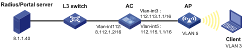
Configuring the AC
1. Configure a RADIUS scheme on the AC:
# Create a RADIUS scheme named rs1, and enter its view.
<AC> system-view
[AC] radius scheme rs1
# Set the server type for the RADIUS scheme. When you use the IMC server, set the server type to extended.
[AC-radius-rs1] server-type extended
# Specify the primary authentication/authorization server, and configure the key for communication with the server.
[AC-radius-rs1] primary authentication 8.1.1.40
[AC-radius-rs1] key authentication simple 123456789
# Specify that the ISP domain name should not be included in the username sent to the RADIUS server.
[AC-radius-rs1] user-name-format without-domain
[AC-radius-rs1] quit
# Specify the NAS IP of the AC for RADIUS.
[AC-radius-rs1] nas-ip 112.113.1.1
[AC-radius-rs1] quit
2. Configure an authentication domain on the AC:
# Configure an ISP domain named dm1, and enter its view.
[AC] domain dm1
# Configure the ISP domain to use RADIUS scheme rs1.
[AC-isp-dm1] authentication portal radius-scheme rs1
[AC-isp-dm1] authorization portal radius-scheme rs1
[AC-isp-dm1] quit
3. Configure portal authentication on the AC:
# Configure the portal server as follows:
¡ Name: 5
¡ IP address: 8.1.1.40
¡ Key: 123456789 (in plaintext)
¡ Port number: 50100
¡ URL: http://8.1.1.40:8080/portal
[AC] portal server 5 ip 8.1.1.40 key simple 123456789 port 50100 url http://8.1.1.40:8080/portal
# Configure a portal-free rule to allow access from the AC to any destinations without portal authentication. This configuration is required only on the AC module.
[AC] portal free-rule 0 source interface bridge-aggregation 1 destination any
# Create VLAN 5 and configure the IP address of VLAN-interface 5 as 112.115.1.1/16.
[AC] vlan 5
[AC-vlan5] quit
[AC] interface vlan 5
[AC-Vlan-interface5] ip address 112.115.1.1 16
[AC-Vlan-interface5] quit
# Create VLAN 3 and configure the IP address of VLAN-interface 3 as 112.113.1.1/16.
[AC] vlan 3
[AC-vlan3] quit
[AC] interface vlan 3
[AC-Vlan-interface3] ip address 112.113.1.1 16
# On the interface connected to the client, specify the authentication domain as dm1 for portal users, and enable direct portal authentication.
[AC–Vlan-interface3] portal domain dm1
[AC–Vlan-interface3] portal server 5 method direct
[AC–Vlan-interface3] quit
# Configure the NAS IP of the AC for portal as 112.113.1.1.
[AC-Vlan-interface3] portal nas-ip 112.113.1.1
[AC–Vlan-interface3] quit
# Specify the IP address of the MAC binding server as 8.1.1.40.
[AC] portal mac-trigger server ip 8.1.1.40
# On the portal authentication-enabled interface, enable MAC-based quick portal authentication.
[AC] interface vlan-interface 3
[AC-Vlan-interface3] portal mac-trigger enable
[AC-Vlan-interface3] quit
Configuring the portal server
This section uses IMC PLAT 5.2 (E0401) and IMC UAM 5.2 (E0402).
1. Configure the portal server:
a. Log in to IMC and click the Service tab.
b. From the navigation tree, select User Access Manager > Portal Service > Server to enter the portal server configuration page, as shown in Figure 48.
The Portal Page field displays http://8.1.1.40:8080/portal, which is the URL of the portal server.
c. Use default values for other parameters.
d. Click OK.
Figure 48 Configuring the portal server
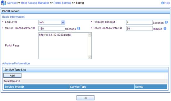
2. Configure the IP address group:
a. From the navigation tree, select User Access Manager > Portal Service > IP Group.
b. Click Add to enter the page shown in Figure 49.
c. Enter the IP group name IP_group.
d. Enter the start IP address 112.113.0.0 and the end IP address 112.113.255.254.
Make sure the client's IP address is in the IP group.
e. Select the service group Ungrouped.
f. Select Normal for Action.
g. Click OK.
Figure 49 Adding an IP address group
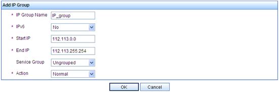
3. Add a portal device:
a. From the navigation tree, select User Access Manager > Portal Service > Device.
b. Click Add to enter the page shown in Figure 50.
c. Enter the device name Portal.
d. Select the IP address 112.113.1.1, which is the IP address of the AC interface that connects to the client.
e. Enter the key 123456789, which must be the same as that configured on the AC.
f. Select No for both Support Server Heartbeat and Support User Heartbeat.
g. Click OK.
Figure 50 Adding a portal device
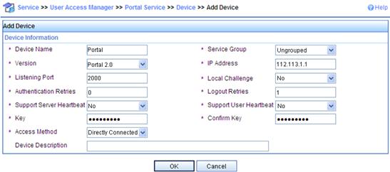
4. Associate the portal device with the IP address group:
a. From the navigation tree, select User Access Manager > Portal Service > Device.
b. As shown in Figure 51, click the icon in the Operation column for device Portal and select Configure Port Group.
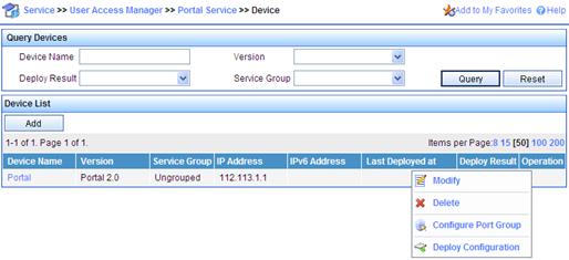
c. On the port group configuration page, click Add to enter the page shown in Figure 52.
d. Enter the port group name hp_portal.
e. Select the configured IP address group IP_group.
The client's IP address must be within this IP address group.
f. Select Supported for Fast Authentication on Smart Terminals.
g. Use default values for other parameters.
h. Click OK.
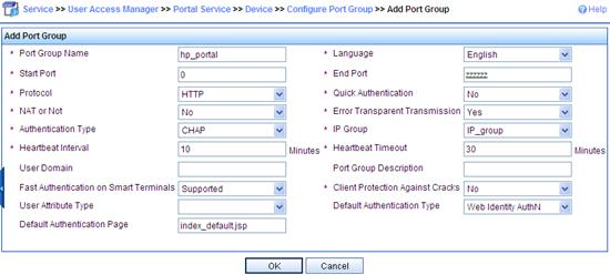
5. Configure an access rule:
a. From the navigation tree, select User Access Manager > Access Rule Management.
b. Click Add to enter the page shown in Figure 53.
c. Enter the access rule name mac-trigger.
d. Use default values for other parameters.
e. Click OK.
Figure 53 Adding an access rule
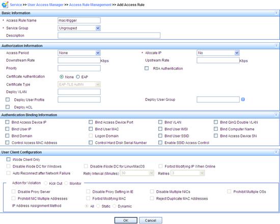
6. Configure fast authentication on smart terminals:
a. From the navigation tree, select User Access Manager > Service Configuration.
b. Click Add to enter the page shown in Figure 54.
c. Enter the service name dot1x.
d. Select mac-trigger for Default Access Rule.
e. Select Portal Fast Authentication on Endpoints.
f. Click OK.
Figure 54 Adding a service configuration
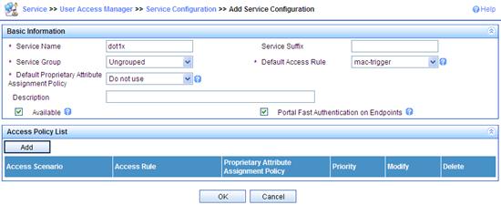
7. Configure the access device:
a. From the navigation tree, select User Access Manager > Access Device Management > Access Device.
b. On the access device configuration page, click Add.
c. Enter and confirm the shared key 123456789.
d. Click Add Manually on the device list.
e. On the Add Access Device Manually window, enter the access device IP address 112.113.1.1 in the Start IP field, and click OK.
Figure 55 Adding an access device
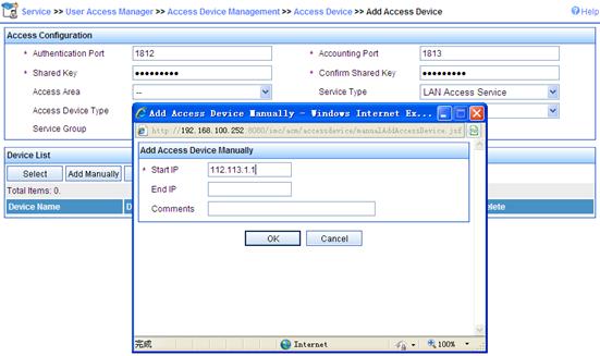
8. Configure the access user:
a. Click the User tab.
b. From the navigation tree, select All Access Users > Ungrouped.
c. Click Add to enter the access user configuration page shown in Figure 56.
d. Enter the user name Portal, the account name dot1x, and the password 123456789.
e. Select 5 for Max. Smart Terminal Bindings for Portal.
You can set this parameter according to actual requirements.
f. Select dot1x in the access service list.
Figure 56 Adding an access user
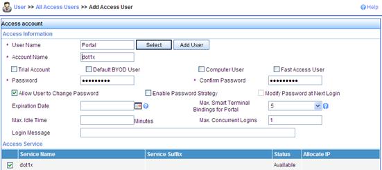
9. Configure HTTP user agent feature identification:
a. Click the Service tab.
b. From the navigation tree, select User Access Manager > Endpoint Identification Management.
c. Click the HTTP User Agent Feature Identification Configuration tab.
The page displays smart terminals in the HTTP User Agent Feature Identification Configuration List. If the list contains no smart terminals, click Add to add devices.
Figure 57 Configuring HTTP user agent feature identification
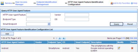
10. Enable BYOD fast authentication:
a. Click the Service tab.
b. From the navigation tree, select User Access Manager > Service Parameters > System Settings.
c. Click BYOD System Settings.
d. Select Yes for Enable Fast Authentication.
e. Use default values for other parameters.
f. Click OK.
Figure 58 Configuring BYOD system settings
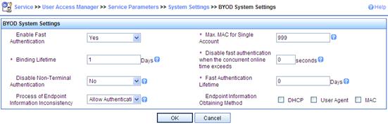
11. From the navigation tree, select User Access Manager > Service Parameters > Validate to validate the configurations.
Verifying the configuration
# Use the client to access an external network, the portal authentication page appears. Enter the username Portal and password 123456789 to log in.
# On the AC, display portal user information.
[AC] display portal user all
Index:2
State:ONLINE
SubState:NONE
ACL:NONE
Work-mode:stand-alone
MAC IP Vlan Interface
----------------------------------------------------------------------------
3ca9-f414-4c20 112.113.0.1 3 Vlan-interface3
Total 1 user(s) matched, 1 listed.
# Disconnect from the external network and then access the network again. The portal authentication page does not appear. On the AC, display portal user information. The output shows that the client has logged in.
[AC] display portal user all
Index:3
State:ONLINE
SubState:NONE
ACL:NONE
Work-mode:stand-alone
MAC IP Vlan Interface
----------------------------------------------------------------------------
3ca9-f414-4c20 112.113.0.1 3 Vlan-interface3
Total 1 user(s) matched, 1 listed.
Configuring IPv6 direct portal authentication
Network requirements
As shown in Figure 59, the wireless user (Client) belongs to VLAN 2 and the AP belongs to VLAN 3. A CMCC portal server is used.
To ensure that the AC can perform direct portal authentication for wireless users, perform the following tasks:
· Assign an IPv4 address to an interface on the AC to exchange portal protocol packets with the IPv4 portal server for IPv6 portal authentication.
· Assign an IPv6 address to an interface on the AC to establish an HTTP connection with the IPv6 portal server for HTTP request redirection.
· Use a RADIUS server as the authentication/accounting server.
Before portal authentication, the wireless user can access only the portal server. After passing portal authentication, the user can access Internet resources.
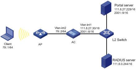
Configuration prerequisites and guidelines
· Configure IP addresses for the client, AC, and servers as shown in Figure 59, and make sure they have IP connectivity between each other.
· Configure the RADIUS server properly to provide authentication/accounting services for users.
Configuration procedure
1. Configure a RADIUS scheme:
# Create a RADIUS scheme named rs1 and enter its view.
<AC> system-view
[AC] radius scheme rs1
# Specify the primary authentication server and primary accounting server, and configure the keys for communication with the servers.
[AC-radius-rs1] primary authentication 111.8.0.244
[AC-radius-rs1] primary accounting 111.8.0.244
[AC-radius-rs1] key authentication simple radius
[AC-radius-rs1] key accounting simple radius
# Specify that the ISP domain name should not be included in the username sent to the RADIUS server.
[AC-radius-rs1] user-name-format without-domain
[AC-radius-rs1] quit
2. Configure an authentication domain:
# Create an ISP domain named dm1 and enter its view.
[AC] domain dm1
# Configure the ISP domain to use RADIUS scheme rs1.
[AC-isp-dm1] authentication portal radius-scheme rs1
[AC-isp-dm1] authorization portal radius-scheme rs1
[AC-isp-dm1] accounting portal radius-scheme rs1
[AC-isp-dm1] quit
# Specify ISP domain dm1 as the default ISP domain. If a user enters the username without the ISP domain name at login, the authentication and accounting methods of the default domain are used for the user.
[AC] domain default enable dm1
3. Configure a WLAN:
# Create WLAN-ESS interface 1 and assign the interface to VLAN 2.
[AC] interface wlan-ess 1
[AC-WLAN-ESS1] port access vlan 2
[AC-WLAN-ESS1] quit
# Create a clear-type WLAN service template numbered 1, set the SSID of the service template to abc, and bind WLAN-ESS interface 1 to this service template.
[AC] wlan service-template 1 clear
[AC-wlan-st-1] ssid abc
[AC-wlan-st-1] bind wlan-ess 1
[AC-wlan-st-1] authentication-method open-system
[AC-wlan-st-1] service-template enable
# Create AP ap1 with model WA3628i-AGN, and set the serial ID of the AP to 210235A29G007C000020.
[AC] wlan ap ap1 model WA3628i-AGN
[AC-wlan-ap-ap1] serial-id 210235A29G007C000020
# Set the radio type to dot11an, map service template 1 to radio 1, and enable radio 1.
[AC-wlan-ap-ap1] radio 1 type dot11an
[AC-wlan-ap-ap1-radio-1] service-template 1
[AC-wlan-ap-ap1-radio-1] radio enable
[AC-wlan-ap-ap1-radio-1] quit
[AC-wlan-ap-ap1] quit
4. Configure portal authentication:
# Configure the IPv4 portal server as follows:
¡ Name: ipv4-srv
¡ IP address: 111.8.27.229
¡ URL: http://111.8.27.229/portal
¡ Server type: CMCC
[AC] portal server ipv4-srv ip 111.8.27.229 url http://111.8.27.229/portal server-type cmcc
# Configure the IPv6 portal server as follows:
¡ Name: ipv6-srv
¡ IP address: 2001::9
¡ URL: http://[2001::9]:8080/portal
¡ Server type: CMCC
[AC] portal server ipv6-web ipv6 2001::9 url http://[2001::9]:8080/portal server-type cmcc
# Configure a portal-free rule to allow access from the AC to any destinations without portal authentication. (Optional. This configuration is required if the AC is a wireless service module in a switch.)
[AC] portal free-rule 0 source interface bridge-aggregation 1 destination any
# On the interface connected to the client, enable direct Layer 3 portal authentication using portal server ipv6-web.
[AC] interface vlan-interface 2
[AC–Vlan-interface2] portal server ipv6-web method direct
[AC–Vlan-interface2] quit
Verifying the configuration
# Connect the wireless client to WLAN abc. (Details not shown.)
# Use a Web browser to access network resources (such as http://[79::12]). All the Web access requests will be redirected to the authentication page http://[2001::9]:8080/portal. After passing the authentication on the authentication page, you can access other network resources.
# Use the display portal user command to display information about the portal user. (Details not shown.)
Troubleshooting portal
Inconsistent keys on the access device and the portal server
Symptom
When a user is forced to access the portal server, the portal server displays a blank webpage, rather than the portal authentication page or an error message.
Analysis
The keys on the access device and those on the portal server are not configured consistently, causing CHAP message exchange failure. As a result, the portal server does not display the authentication page.
Solution
· Use the display portal server command to display the key for the portal server on the access device and view the key for the access device on the portal server.
· Use the portal server command to modify the key on the access device or modify the key for the access device on the portal server to make sure that the keys are consistent.
Incorrect server port number on the access device
Symptom
After a user passes the portal authentication, you cannot force the user to log off by executing the portal delete-user command on the access device, but the user can log off by using the disconnect attribute on the authentication client.
Analysis
When you execute the portal delete-user command on the access device to force the user to log off, the access device actively sends a REQ_LOGOUT message to the portal server. The default listening port of the portal server is 50100. However, if the listening port configured on the access device is not 50100, the destination port of the REQ_LOGOUT message is not the actual listening port on the server, and the portal server cannot receive the REQ_LOGOUT message. As a result, you cannot force the user to log off the portal server.
When the user uses the disconnect attribute on the client to log off, the portal server actively sends a REQ_LOGOUT message to the access device. The source port is 50100 and the destination port of the ACK_LOGOUT message from the access device is the source port of the REQ_LOGOUT message so that the portal server can receive the ACK_LOGOUT message correctly, no matter whether the listening port is configured on the access device. The user can log off the portal server.
Solution
Use the display portal server command to display the listening port of the portal server configured on the access device and use the portal server command in the system view to modify it to make sure that it is the actual listening port of the portal server.