- Table of Contents
-
- 07-Security Configuration Guide
- 00-Preface
- 01-Security Overview
- 02-AAA Configuration
- 03-802.1X Configuration
- 04-MAC Authentication Configuration
- 05-Portal Configuration
- 06-Port Security Configuration
- 07-User Profile Configuration
- 08-Password Control Configuration
- 09-Public Key Configuration
- 10-PKI Configuration
- 11-SSH Configuration
- 12-SSL Configuration
- 13-SSL VPN Configuration
- 14-TCP Attack Protection Configuration
- 15-ARP Attack Protection Configuration
- 16-IPsec Configuration
- 17-ALG Configuration
- 18-Firewall Configuration
- 19-Session Management Configuration
- 20-Web Filtering Configuration
- 21-User Isolation Configuration
- 22-Source IP Address Verification Configuration
- 23-FIPS Configuration
- 24-Protocol Packet Rate Limit Configuration
- 25-Attack detection and protection configuration
- Related Documents
-
| Title | Size | Download |
|---|---|---|
| 17-ALG Configuration | 164.47 KB |
Configuring ALG
The term "router" in this document refers to both routers and routing-capable WX series access controllers.
Support for this feature depends on the device model. For more information, see About the WX Series Access Controllers Configuration Guides.
Application Level Gateway (ALG) processes the payload information of application layer packets to make sure data connections can be established.
NAT typically translates only IP address and port information in packet headers and does not analyze fields in application layer payloads. However, the packet payloads of some protocols may contain IP address or port information, which may cause problems if not translated. For example, an FTP application involves both data connection and control connection, and data connection establishment dynamically depends on the payload information of the control connection.
ALG works with NAT or ASPF to implement the following functions:
· Address translation—Resolves the source IP address, port, protocol type (TCP or UDP), and remote IP address information in packet payloads.
· Data connection detection—Extracts information required for data connection establishment and establishing data connections for data exchange.
· Application layer status checking—Inspects the status of the application layer protocol in packets. Packets with correct states have their status updated and are sent for further processing, whereas packets with incorrect states are dropped.
Support for these functions depends on the application layer protocol.
ALG can process the following protocol packets:
· DNS
· FTP
· H.323, including RAS, H.225, and H.245
· ILS
· MSN
· NBT
· PPTP
· RTSP
· SCCP
· SIP
· SQLNET, a language in Oracle
· TFTP
ALG process
The following example describes the FTP operation of an ALG-enabled router.
As shown in Figure 1, the host on the external network accesses the FTP server on the internal network in passive mode through the ALG-enabled router.
Figure 1 Network diagram for ALG-enabled FTP application in passive mode
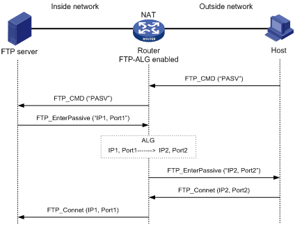
The communication process includes the following steps:
1. Establishing a control connection.
The host sends a TCP connection request to the server. If a TCP connection is established, the server and the host enter the user authentication stage.
2. Authenticating the user.
The host sends the server an authentication request, which contains the FTP commands (user and password) and the contents.
When the request passes through the ALG-enabled device, the commands in the payload of the packet are resolved and used to check whether the protocol state transition is correctly proceeding. If not, the request will be dropped. In this way, ALG protects the server against clients that send packets with state errors or log in to the server with unauthorized user accounts.
An authentication request with the correct state is forwarded by the ALG-enabled device to the server, which authenticates the host according to the information in the packet.
3. Establishing a data connection.
If the host passes the authentication, a data connection is established between it and the server. If the host is accessing the server in passive mode, the server sends the host a PASV response that uses its private network address and port number (IP1, Port1). When the response arrives at the ALG-enabled device, the device resolves the packet and translates the server's private network address and port number into the server's public network address and port number (IP2, Port2) respectively. Then, the device uses the public network address and port number to establish a data connection with the host.
4. Exchanging data.
The host and the FTP server exchange data through the established data connection.
Enabling ALG
|
Step |
Command |
Remarks |
|
1. Enter system view. |
system-view |
N/A |
|
2. Enable ALG. |
alg { all | dns | ftp | h323 | ils | msn | nbt | pptp | qq | rtsp | sccp | sip | sqlnet | tftp } |
Optional. By default, ALG is enabled for all protocols. |
FTP ALG configuration example
The example describes ALG configurations, assuming other required configurations on the server and client have been done.
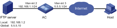
Network requirements
As shown in Figure 2, a company uses the private network segment 192.168.1.0/24, and has four public network addresses: 5.5.5.1, 5.5.5.9, 5.5.5.10, and 5.5.5.11. The company wants to provide FTP services to the outside.
Configure NAT and ALG on the AC so that hosts on the external network can access the FTP server on the internal network.
Configuration procedure
# Configure the address pool and ACL.
<AC> system-view
[AC] nat address-group 1 5.5.5.9 5.5.5.11
[AC] acl number 2001
[AC-acl-basic-2001] rule permit
[AC-acl-basic-2001] quit
# Enable ALG for FTP.
[AC] alg ftp
# Configure NAT.
[AC] interface vlan-interface 3
[AC-Vlan-interface3] nat outbound 2001 address-group 1
# Configure internal FTP server.
[AC-Vlan-interface3] nat server protocol tcp global 5.5.5.10 ftp inside 192.168.1.2 ftp
SIP/H.323 ALG configuration example
H.323 ALG configuration is similar to SIP ALG configuration. This example describes SIP ALG configuration, assuming other required configurations on the server and client have been done.
Network requirements
As shown in Figure 3, a company uses the private network segment 192.168.1.0/24, and has four public network addresses: 5.5.5.1, 5.5.5.9, 5.5.5.10, and 5.5.5.11. SIP UA 1 is on the internal network and SIP UA 2 is on the external network.
Configure NAT and ALG on the AC to enable SIP UA 1 and SIP UA 2 to communicate by using their aliases, and to enable SIP UA 1 to select an IP address from the range 5.5.5.9 to 5.5.5.11 when registering with the SIP server on the external network.
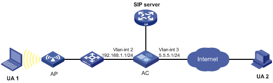
Configuration procedure
# Configure the address pool and ACL.
<AC> system-view
[AC] nat address-group 1 5.5.5.9 5.5.5.11
[AC] acl number 2001
[AC-acl-basic-2001] rule permit source 192.168.1.0 0.0.0.255
[AC-acl-basic-2001] rule deny
[AC-acl-basic-2001] quit
# Enable ALG for SIP.
[AC] alg sip
# Configure NAT.
[AC] interface vlan-interface 3
[AC-Vlan-interface3] nat outbound 2001 address-group 1
NBT ALG configuration example
The example describes ALG configurations, assuming other required configurations on the server and client have been done.
Network requirements
As shown in Figure 4, a company using the private network segment 192.168.1.0/24 wants to provide NBT services to the outside.
Configure NAT and ALG on the AC so that Host A uses 5.5.5.9 as its external IP address, the WINS server uses 5.5.5.10 as its external IP address, and Host B can access the WINS server and Host A by using host names.
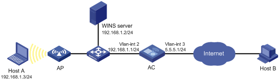
Configuration procedure
# Configure a static NAT entry.
<AC> system-view
[AC] nat static 192.168.1.3 5.5.5.9
# Enable ALG for NBT.
[AC] alg nbt
# Configure NAT.
[AC] interface vlan-interface 3
[AC-Vlan-interface3] nat outbound static
# Configure the internal WINS server.
[AC-Vlan-interface3] nat server protocol udp global 5.5.5.10 137 inside 192.168.1.2 137
[AC-Vlan-interface3] nat server protocol udp global 5.5.5.10 138 inside 192.168.1.2 138
[AC-Vlan-interface3] nat server protocol tcp global 5.5.5.10 139 inside 192.168.1.2 139