- Table of Contents
-
- 07-Security Configuration Guide
- 00-Preface
- 01-Security Overview
- 02-AAA Configuration
- 03-802.1X Configuration
- 04-MAC Authentication Configuration
- 05-Portal Configuration
- 06-Port Security Configuration
- 07-User Profile Configuration
- 08-Password Control Configuration
- 09-Public Key Configuration
- 10-PKI Configuration
- 11-SSH Configuration
- 12-SSL Configuration
- 13-SSL VPN Configuration
- 14-TCP Attack Protection Configuration
- 15-ARP Attack Protection Configuration
- 16-IPsec Configuration
- 17-ALG Configuration
- 18-Firewall Configuration
- 19-Session Management Configuration
- 20-Web Filtering Configuration
- 21-User Isolation Configuration
- 22-Source IP Address Verification Configuration
- 23-FIPS Configuration
- 24-Protocol Packet Rate Limit Configuration
- 25-Attack detection and protection configuration
- Related Documents
-
| Title | Size | Download |
|---|---|---|
| 02-AAA Configuration | 1.70 MB |
AAA configuration considerations and task list
Configuring AAA methods for ISP domains
Configuring ISP domain attributes
Configuring authentication methods for an ISP domain
Configuring authorization methods for an ISP domain
Configuring accounting methods for an ISP domain
Configuring local EAP authentication
Configuring the local EAP authentication server
Configuring a NAS ID-VLAN binding
Displaying and maintaining AAA
HWTACACS authentication and authorization for Telnet users
Local authentication and HWTACACS authorization for Telnet users
LDAP authentication for Telnet users
AAA for portal users by a RADIUS server
Configuring the RADIUS server on IMC 3.6
Configuring the RADIUS server on IMC 5.0
Configuring the portal server on IMC 3.6
Configuring the portal server on IMC 5.0
AAA for 802.1X users by a RADIUS server
Configuring the RADIUS server on IMC 3.6
Configuring the RADIUS server on IMC 5.0
Local EAP authentication and authorization for 802.1X users
RADIUS offload for 802.1X users
Level switching authentication for Telnet users by an HWTACACS server
Local EAP authentication for 802.1X users by an LDAP server
Temporary access control of wireless users
Configuring AAA
Overview
Authentication, Authorization, and Accounting (AAA) provides a uniform framework for implementing network access management. It provides the following security functions:
· Authentication—Identifies users and determines whether a user is valid.
· Authorization—Grants user rights and controls user access to resources and services. For example, a user who has successfully logged in to the device can be granted read and print permissions to the files on the device.
· Accounting—Records all network service usage information, including service type, start time, and traffic. It provides information required for accounting and allows for network security surveillance.
AAA typically uses a client/server model, as shown in Figure 1. The client runs on the network access server (NAS), which is also called the access device. The server maintains user information centrally. In an AAA network, the NAS is a server for users but a client for AAA servers.
Figure 1 AAA application scenario
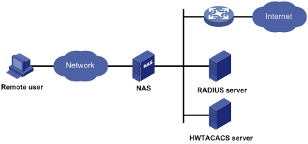
The NAS uses the authentication server to authenticate any user who tries to log in, use network resources, or access other networks. The NAS transparently transmits authentication, authorization, and accounting information between the user and the servers. The RADIUS and HWTACACS protocols define how a NAS and a remote server exchange user information.
The network shown in Figure 1 includes a RADIUS server and an HWTACACS server. You can use different servers to implement different security functions. For example, you can use the HWTACACS server for authentication and authorization, and the RADIUS server for accounting.
You can implement any of the security functions provided by AAA as needed. For example, if your company wants employees to be authenticated before they access specific resources, you would configure an authentication server. If network usage information is needed, you would also configure an accounting server.
AAA can be implemented through multiple protocols. The device supports RADIUS, HWTACACS, and LDAP, and RADIUS is used most often.
RADIUS
Remote Authentication Dial-In User Service (RADIUS) is a distributed information interaction protocol that uses a client/server model. It can protect networks against unauthorized access and is often used in network environments that require both high security and remote user access.
RADIUS uses UDP port 1812 for authentication and UDP port 1813 for accounting.
RADIUS was originally designed for dial-in user access. RADIUS has been extended to support additional access methods, including Ethernet and ADSL. RADIUS provides access authentication, authorization, and accounting services. The accounting function collects and records network resource usage information.
Client/server model
RADIUS clients run on NASs located throughout the network. NASs pass user information to RADIUS servers, and reject or accept user access requests depending on the responses from RADIUS servers.
The RADIUS server runs on the computer or workstation at the network center and maintains information related to user authentication and network access. It receives connection requests, authenticates users, and returns access control information (for example, rejecting or accepting the user access request) to the clients.
The RADIUS server typically maintains the following databases: Users, Clients, and Dictionary, as shown in Figure 2.
Figure 2 RADIUS server databases
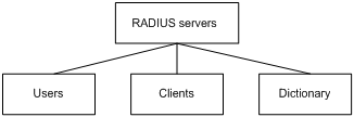
· Users—Stores user information, such as usernames, passwords, applied protocols, and IP addresses.
· Clients—Stores information about RADIUS clients, such as shared keys and IP addresses.
· Dictionary—Stores RADIUS protocol attributes and their values.
Security and authentication mechanisms
The RADIUS client and the RADIUS server use a shared key to authenticate RADIUS packets and encrypt user passwords exchanged between them. For security, this key must be manually configured on the client and the server.
RADIUS servers support multiple authentication protocols, including PPP PAP and CHAP. A RADIUS server can also act as the client of another AAA server to provide authentication proxy services.
Basic RADIUS message exchange process
Figure 3 illustrates the interactions between the host, the RADIUS client, and the RADIUS server.
Figure 3 Basic RADIUS message exchange process
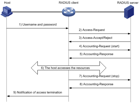
RADIUS uses the following workflow:
1. The host initiates a connection request that includes the user's username and password to the RADIUS client.
2. The RADIUS client sends an authentication request (Access-Request) to the RADIUS server after it received the username and password. The user password is encrypted with the MD5 algorithm and the shared key.
3. The RADIUS server authenticates the username and password. If the authentication succeeds, the server returns an Access-Accept message that includes the user's authorization information. If the authentication fails, the server returns an Access-Reject message.
4. The RADIUS client permits or denies the user according to the returned authentication result. If the result permits the user, the RADIUS client sends a start-accounting request (Accounting-Request) to the RADIUS server.
5. The RADIUS server returns an acknowledgement (Accounting-Response) and starts accounting.
6. The user accesses the network resources.
7. The host requests the RADIUS client to tear down the connection and the RADIUS client sends a stop-accounting request (Accounting-Request) to the RADIUS server.
8. The RADIUS server returns an acknowledgement (Accounting-Response) and stops accounting for the user.
RADIUS packet format
RADIUS uses UDP to transmit messages. To ensure smooth message exchange between the RADIUS server and the client, RADIUS uses a timer management mechanism, a retransmission mechanism, and a backup server mechanism. Figure 4 shows the RADIUS packet format.
Figure 4 RADIUS packet format
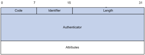
Descriptions of the fields are as follows:
· The Code field (1 byte long) indicates the type of the RADIUS packet.
Table 1 Main values of the Code field
|
Code |
Packet type |
Description |
|
1 |
Access-Request |
From the client to the server. A packet of this type includes user information for the server to authenticate the user. It must contain the User-Name attribute and can optionally contain the attributes of NAS-IP-Address, User-Password, and NAS-Port. |
|
2 |
Access-Accept |
From the server to the client. If all attribute values included in the Access-Request are acceptable, the authentication succeeds, and the server sends an Access-Accept response. |
|
3 |
Access-Reject |
From the server to the client. If any attribute value included in the Access-Request is unacceptable, the authentication fails, and the server sends an Access-Reject response. |
|
4 |
Accounting-Request |
From the client to the server. A packet of this type includes user information for the server to start or stop accounting for the user. The Acct-Status-Type attribute in the packet indicates whether to start or stop accounting. |
|
5 |
Accounting-Response |
From the server to the client. The server sends a packet of this type to notify the client that it has received the Accounting-Request and has successfully recorded the accounting information. |
· The Identifier field (1 byte long) is used to match request packets and response packets and to detect duplicate request packets. Request and response packets of the same type have the same identifier.
· The Length field (2 bytes long) indicates the length of the entire packet, including the Code, Identifier, Length, Authenticator, and Attributes fields. Bytes beyond this length are considered padding and are ignored by the receiver. If the length of a received packet is less than this length, the packet is dropped. The value of this field is in the range 20 to 4096.
· The Authenticator field (16 bytes long) is used to authenticate responses from the RADIUS server and to encrypt user passwords. There are two types of authenticators: request authenticator and response authenticator.
· The Attributes field (variable in length) includes the specified authentication, authorization, and accounting information that defines the configuration details of the request or response. This field may contain multiple attributes, each with three sub-fields:
¡ Type—(1 byte long) Type of the attribute. It is in the range of 1 to 255. Commonly used RADIUS attributes are defined in RFC 2865, RFC 2866, RFC 2867, and RFC 2868. Table 2 shows a list of the attributes. For more information, see "Commonly used standard RADIUS attributes."
¡ Length—(1 byte long) Length of the attribute in bytes, including the Type, Length, and Value sub-fields.
¡ Value—(Up to 253 bytes) Value of the attribute. Its format and content depend on the Type and Length sub-fields.
Table 2 Commonly used RADIUS attributes
|
No. |
Attribute |
No. |
Attribute |
|
1 |
User-Name |
45 |
Acct-Authentic |
|
2 |
User-Password |
46 |
Acct-Session-Time |
|
3 |
CHAP-Password |
47 |
Acct-Input-Packets |
|
4 |
NAS-IP-Address |
48 |
Acct-Output-Packets |
|
5 |
NAS-Port |
49 |
Acct-Terminate-Cause |
|
6 |
Service-Type |
50 |
Acct-Multi-Session-Id |
|
7 |
Framed-Protocol |
51 |
Acct-Link-Count |
|
8 |
Framed-IP-Address |
52 |
Acct-Input-Gigawords |
|
9 |
Framed-IP-Netmask |
53 |
Acct-Output-Gigawords |
|
10 |
Framed-Routing |
54 |
(unassigned) |
|
11 |
Filter-ID |
55 |
Event-Timestamp |
|
12 |
Framed-MTU |
56-59 |
(unassigned) |
|
13 |
Framed-Compression |
60 |
CHAP-Challenge |
|
14 |
Login-IP-Host |
61 |
NAS-Port-Type |
|
15 |
Login-Service |
62 |
Port-Limit |
|
16 |
Login-TCP-Port |
63 |
Login-LAT-Port |
|
17 |
(unassigned) |
64 |
Tunnel-Type |
|
18 |
Reply-Message |
65 |
Tunnel-Medium-Type |
|
19 |
Callback-Number |
66 |
Tunnel-Client-Endpoint |
|
20 |
Callback-ID |
67 |
Tunnel-Server-Endpoint |
|
21 |
(unassigned) |
68 |
Acct-Tunnel-Connection |
|
22 |
Framed-Route |
69 |
Tunnel-Password |
|
23 |
Framed-IPX-Network |
70 |
ARAP-Password |
|
24 |
State |
71 |
ARAP-Features |
|
25 |
Class |
72 |
ARAP-Zone-Access |
|
26 |
Vendor-Specific |
73 |
ARAP-Security |
|
27 |
Session-Timeout |
74 |
ARAP-Security-Data |
|
28 |
Idle-Timeout |
75 |
Password-Retry |
|
29 |
Termination-Action |
76 |
Prompt |
|
30 |
Called-Station-Id |
77 |
Connect-Info |
|
31 |
Calling-Station-Id |
78 |
Configuration-Token |
|
32 |
NAS-Identifier |
79 |
EAP-Message |
|
33 |
Proxy-State |
80 |
Message-Authenticator |
|
34 |
Login-LAT-Service |
81 |
Tunnel-Private-Group-id |
|
35 |
Login-LAT-Node |
82 |
Tunnel-Assignment-id |
|
36 |
Login-LAT-Group |
83 |
Tunnel-Preference |
|
37 |
Framed-AppleTalk-Link |
84 |
ARAP-Challenge-Response |
|
38 |
Framed-AppleTalk-Network |
85 |
Acct-Interim-Interval |
|
39 |
Framed-AppleTalk-Zone |
86 |
Acct-Tunnel-Packets-Lost |
|
40 |
Acct-Status-Type |
87 |
NAS-Port-Id |
|
41 |
Acct-Delay-Time |
88 |
Framed-Pool |
|
42 |
Acct-Input-Octets |
89 |
(unassigned) |
|
43 |
Acct-Output-Octets |
90 |
Tunnel-Client-Auth-id |
|
44 |
Acct-Session-Id |
91 |
Tunnel-Server-Auth-id |
Extended RADIUS attributes
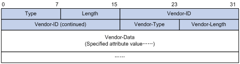
Attribute 26 (Vendor-Specific), an attribute defined in RFC 2865, allows a vendor to define extended attributes to implement functions that the standard RADIUS protocol does not provide.
A vendor can encapsulate multiple sub-attributes as TLVs in attribute 26 to provide extended functions. As shown in Figure 5, a sub-attribute encapsulated in attribute 26 consists of the following parts:
· Vendor-ID—ID of the vendor. Its most significant byte is 0. The other three bytes contains a code that is compliant to RFC 1700. The vendor ID of H3C is 25506. For more information about the proprietary RADIUS sub-attributes of H3C, see "H3C proprietary RADIUS sub-attributes."
· Vendor-Type—Type of the sub-attribute.
· Vendor-Length—Length of the sub-attribute.
· Vendor-Data—Contents of the sub-attribute.
Figure 5 Format of attribute 26
HWTACACS
HWTACACS typically provides AAA services for PPP, VPDN, and terminal users. In a typical HWTACACS scenario, terminal users need to log in to the NAS. Working as the HWTACACS client, the NAS sends users' usernames and passwords to the HWTACACS server for authentication. After passing authentication and obtaining authorized rights, a user logs in to the device and performs operations. The HWTACACS server records the operations that each user performs.
Differences between HWTACACS and RADIUS
HWTACACS and RADIUS have many features in common, including using a client/server model, using shared keys for user information security, and providing flexibility and extensibility. Table 3 lists the primary differences.
Table 3 Primary differences between HWTACACS and RADIUS
|
HWTACACS |
RADIUS |
|
Uses TCP, which provides more reliable network transmission. |
Uses UDP, which provides higher transport efficiency. |
|
Encrypts the entire packet except for the HWTACACS header. |
Encrypts only the user password field in an authentication packet. |
|
Protocol packets are complicated and authorization is independent of authentication. Authentication and authorization can be deployed on different HWTACACS servers. |
Protocol packets are simple and the authorization process is combined with the authentication process. |
|
Supports authorization of configuration commands. Access to commands depends on both the user level and AAA authorization. A user can use only commands that are at, or lower than, the user level and authorized by the HWTACACS server. |
Does not support authorization of configuration commands. Access to commands solely depends on the level of the user. A user can use all the commands at, or lower than, the user level. |
Basic HWTACACS message exchange process
The following example describes how HWTACACS performs user authentication, authorization, and accounting for a Telnet user.
Figure 6 Basic HWTACACS message exchange process for a Telnet user
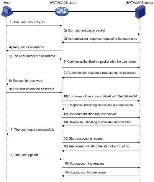
HWTACACS operates using the following workflow:
1. A Telnet user sends an access request to the HWTACACS client.
2. The HWTACACS client sends a start-authentication packet to the HWTACACS server when it receives the request.
3. The HWTACACS server sends back an authentication response to request the username.
4. Upon receiving the response, the HWTACACS client asks the user for the username.
5. The user enters the username.
6. After receiving the username from the user, the HWTACACS client sends the server a continue-authentication packet that includes the username.
7. The HWTACACS server sends back an authentication response to request the login password.
8. Upon receipt of the response, the HWTACACS client prompts the user for the login password.
9. The user enters the password.
10. After receiving the login password, the HWTACACS client sends the HWTACACS server a continue-authentication packet that includes the login password.
11. The HWTACACS server sends back an authentication response to indicate that the user has passed authentication.
12. The HWTACACS client sends the user authorization request packet to the HWTACACS server.
13. The HWTACACS server sends back the authorization response, indicating that the user is now authorized.
14. The HWTACACS client pushes its CLI to the user.
15. The HWTACACS client sends a start-accounting request to the HWTACACS server.
16. The HWTACACS server sends back an accounting response, indicating that it has received the start-accounting request.
17. The user logs off.
18. The HWTACACS client sends a stop-accounting request to the HWTACACS server.
19. The HWTACACS server sends back a stop-accounting response, indicating that the stop-accounting request has been received.
LDAP
Based on TCP/IP, the Lightweight Directory Access Protocol (LDAP) provides standard multi-platform directory service. LDAP was developed on the basis of the X.500 protocol, and improves the read/write interactive access, and browse and search functions of X.500. It is suitable for storing data that is not often changed.
LDAP is typically used to store user information. For example, Microsoft Windows uses Active Directory Server to store user information and user group information for login authentication and authorization.
LDAP directory service
LDAP uses directories to maintain organization, personnel, and resource information. The directories are organized in a tree structure and include entries. An entry is a set of attributes with distinguished names (DNs).
The LDAP directory service is based on a client/server model. All directory information is stored in the LDAP server. Commonly used LDAP server products include Microsoft Active Directory Server, IBM Tivoli Directory Server, and Sun ONE Directory Server.
LDAP authentication and authorization
LDAP defines a set of operations to implement functions. LDAP operations for authentication and authorization are the bind operation and search operation:
· Bind operation—Allows an LDAP client to establish a connection with the LDAP server, obtain the access rights to the LDAP server, and check the validity of user information.
· Search operation—Constructs search conditions and obtains the directory resource information of the LDAP server.
The basic LDAP authentication process is as follows:
1. An LDAP client uses the LDAP server administrator DN to bind with the LDAP server, establishes a connection to the server, and obtains the search rights.
2. The LDAP client, using the username in the authentication information of a user, constructs search conditions to search for the user in the specified root directory of the server, and obtains a user DN list.
3. The LDAP client uses each user DN in the obtained user DN list and the user password to bind with the LDAP server. If a binding succeeds, the user is legal.
The LDAP authorization process is similar to the LDAP authentication process, except that the client obtains the authorization information and the user DN list at step 2 in the workflow.
· If the authorization information meets the authorization requirements, the authorization process ends.
· If the authorization information does not meet the authorization requirements, the client sends an administrator bind request to the LDAP server to obtain search right for authorization information about users on the user DN list.
Basic LDAP message exchange process
The following example illustrates the basic message exchange process during LDAP authentication and authorization for a Telnet user.
Figure 7 Basic message exchange process for LDAP authentication of a Telnet user
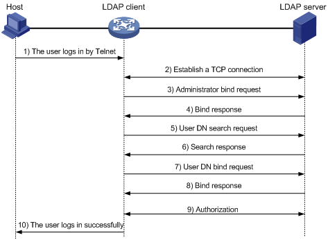
The basic message exchange process during LDAP authentication and authorization is as follows:
1. A Telnet user initiates a connection request and sends the username and password to the LDAP client.
2. After receiving the request, the LDAP client establishes a TCP connection with the LDAP server.
3. To obtain the search right, the LDAP client uses the administrator DN and password to send an administrator bind request to the LDAP server.
4. The LDAP server processes the request. If the bind operation is successful, the LDAP server sends an acknowledgement to the LDAP client.
5. The LDAP client sends a user DN search request with the username of the Telnet user to the LDAP server.
6. After receiving the request, the LDAP server searches for the user DN by the base DN, search scope, and filtering conditions. If a match is found, the LDAP server sends a response to notify the LDAP client of the successful search. There may be one or more user DNs found.
7. The LDAP client uses the obtained user DN and the entered user password as parameters to send a user DN bind request to the LDAP server, which checks whether the user password is correct.
8. The LDAP server processes the request, and sends a response to notify the LDAP client of the bind operation result. If the bind operation fails, the LDAP client uses another obtained user DN as the parameter to send a user DN bind request to the LDAP server. This process continues until a DN is bound successfully or all DNs fail to be bound. If all user DNs fail to be bound, the LDAP client notifies the user of the login failure and denies the access request.
9. The LDAP client and server exchange authorization messages. If another scheme, for example, an HWTACACS scheme, is expected for authorization, the LDAP client exchanges authorization messages with the HWTACACS authorization server instead.
10. After successful authorization, the LDAP client notifies the user of the successful login.
Domain-based user management
A NAS manages users based on ISP domains. On a NAS, each user belongs to one ISP domain. A NAS determines the ISP domain for a user by the username entered by the user at login, as shown in Figure 8.
Figure 8 Determining the ISP domain of a user by the username
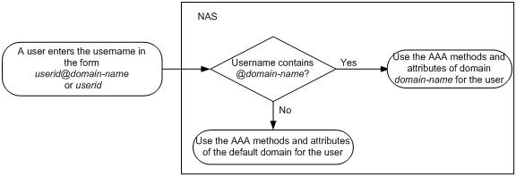
Authentication, authorization, and accounting of a user depends on the AAA methods configured for the domain that the user belongs to. If no specific AAA methods are configured for the domain, the default methods are used. By default, a domain uses local authentication, local authorization, and local accounting.
AAA allows you to manage users based on their access types:
· LAN users—Users on a LAN who must pass 802.1X or MAC address authentication to access the network.
· Login users—Users who want to log in to the device, including SSH users, Telnet users, Web users, FTP users, and terminal users.
· Portal users—Users who must pass portal authentication to access the network.
· PPP users—Users who access the network through PPP. Support for PPP users depends on the device model. For more information, see About the H3C Access Controllers Configuration Guides.
In addition, AAA provides the following login services to enhance device security:
· Command authorization—Enables the NAS to defer to the authorization server to determine whether a command entered by a login user is permitted, and allows login users to execute only authorized commands. For more information about command authorization, see Fundamentals Configuration Guide.
· Command accounting—Allows the accounting server to record all commands executed or successfully authorized on the device. For more information about command accounting, see Fundamentals Configuration Guide.
· Level switching authentication—Allows the authentication server to authenticate users who perform privilege level switching. When users pass level switching authentication, they can switch their user privilege levels without logging out and disconnecting current connections. For more information about user privilege level switching, see Fundamentals Configuration Guide.
You can configure different AAA methods for different types of users in a domain. See "Configuring AAA methods for ISP domains."
Protocols and standards
The following protocols and standards are related to AAA, RADIUS, HWTACACS, and LDAP:
· RFC 2865, Remote Authentication Dial In User Service (RADIUS)
· RFC 2866, RADIUS Accounting
· RFC 2867, RADIUS Accounting Modifications for Tunnel Protocol Support
· RFC 2868, RADIUS Attributes for Tunnel Protocol Support
· RFC 2869, RADIUS Extensions
· RFC 1492, An Access Control Protocol, Sometimes Called TACACS
· RFC 1777, Lightweight Directory Access Protocol
· RFC 2251, Lightweight Directory Access Protocol (v3)
RADIUS attributes
This section provides tables of commonly used standard RADIUS attributes and H3C proprietary RADIUS sub-attributes.
Commonly used standard RADIUS attributes
|
No. |
Attribute |
Description |
|
1 |
User-Name |
Name of the user to be authenticated. |
|
2 |
User-Password |
User password for PAP authentication, only present in Access-Request packets when PAP authentication is used. |
|
3 |
CHAP-Password |
Digest of the user password for CHAP authentication, only present in Access-Request packets when CHAP authentication is used. |
|
4 |
NAS-IP-Address |
IP address for the server to use to identify a client. A client is typically identified by the IP address of its access interface. This attribute is only present in Access-Request packets. |
|
5 |
NAS-Port |
Physical port of the NAS that the user accesses. |
|
6 |
Service-Type |
Type of service that the user has requested or type of service to be provided. · 2—802.1X authentication. · 10—MAC authentication. |
|
7 |
Framed-Protocol |
Encapsulation protocol for framed access. |
|
8 |
Framed-IP-Address |
IP address assigned to the user. |
|
11 |
Filter-ID |
Name of the filter list. |
|
12 |
Framed-MTU |
MTU for the data link between the user and NAS. For example, with 802.1X EAP authentication, NAS uses this attribute to notify the server of the MTU for EAP packets, so as to avoid oversized EAP packets. |
|
14 |
Login-IP-Host |
IP address of the NAS interface that the user accesses. |
|
15 |
Login-Service |
Type of the service that the user uses for login. |
|
18 |
Reply-Message |
Text to be displayed to the user, which can be used by the server to communicate information, for example, the reason of the authentication failure. |
|
26 |
Vendor-Specific |
Vendor specific, proprietary attribute. A packet can contain one or more proprietary attributes, each of which can contain one or more sub-attributes. |
|
27 |
Session-Timeout |
Maximum service duration for the user before termination of the session. |
|
28 |
Idle-Timeout |
Maximum idle time permitted for the user before termination of the session. |
|
31 |
Calling-Station-Id |
User identification that the NAS sends to the server. For the LAN access service provided by an H3C device, this attribute includes the MAC address of the user in the format HH-HH-HH-HH-HH-HH. |
|
32 |
NAS-Identifier |
Identification that the NAS uses to identify itself to the RADIUS server. |
|
40 |
Acct-Status-Type |
Type of the Accounting-Request packet. Possible values include: · 1—Start. · 2—Stop. · 3—Interim-Update. · 4—Reset-Charge. · 7—Accounting-On. (Defined in the 3rd Generation Partnership Project.) · 8—Accounting-Off. (Defined in the 3rd Generation Partnership Project.) · 9 to 14—Reserved for tunnel accounting. · 15—Reserved for failed. |
|
45 |
Acct-Authentic |
Authentication method used by the user. Possible values include: · 1—RADIUS. · 2—Local. · 3—Remote. |
|
60 |
CHAP-Challenge |
CHAP challenge generated by the NAS for MD5 calculation during CHAP authentication. |
|
61 |
NAS-Port-Type |
Type of the physical port of the NAS that is authenticating the user. Possible values include: · 15—Ethernet. · 16—Any type of ADSL. · 17—Cable (with cable for cable TV). · 19—WLAN-IEEE 802.11. · 201—VLAN. · 202—ATM. If the port is an ATM or Ethernet one and VLANs are implemented on it, the value of this attribute is 201. |
|
79 |
EAP-Message |
Used to encapsulate EAP packets to allow RADIUS to support EAP authentication. |
|
80 |
Message-Authenticator |
Used for authentication and verification of authentication packets to prevent spoofing Access-Requests. This attribute is present when EAP authentication is used. |
|
87 |
NAS-Port-Id |
String for describing the port of the NAS that is authenticating the user. |
H3C proprietary RADIUS sub-attributes
|
No. |
Sub-attribute |
Description |
|
1 |
Input-Peak-Rate |
Peak rate in the direction from the user to the NAS, in bps. |
|
2 |
Input-Average-Rate |
Average rate in the direction from the user to the NAS, in bps. |
|
3 |
Input-Basic-Rate |
Basic rate in the direction from the user to the NAS, in bps. |
|
4 |
Output-Peak-Rate |
Peak rate in the direction from the NAS to the user, in bps. |
|
5 |
Output-Average-Rate |
Average rate in the direction from the NAS to the user, in bps. |
|
6 |
Output-Basic-Rate |
Basic rate in the direction from the NAS to the user, in bps. |
|
15 |
Remanent_Volume |
Total remaining available traffic for the connection, in different units for different server types. |
|
20 |
Command |
Operation for the session, used for session control. Possible values include: · 1—Trigger-Request. · 2—Terminate-Request. · 3—SetPolicy. · 4—Result. · 5—PortalClear. |
|
24 |
Control_Identifier |
Identification for retransmitted packets. For retransmitted packets from the same session, this attribute must be the same value. For retransmitted packets from different sessions, this attribute does not have to be the same value. The client response from a retransmitted packet must also include this attribute and the value of this attribute must be the same. For Accounting-Request packets from the start, stop, and interim update types, the Control-Identifier attribute does not take effect. |
|
25 |
Result_Code |
Result of the Trigger-Request or SetPolicy operation, zero for success and any other value for failure. |
|
26 |
Connect_ID |
Index of the user connection. |
|
28 |
Ftp_Directory |
FTP user working directory. When the RADIUS client acts as the FTP server, this attribute is used to set the FTP directory for an FTP user on the RADIUS client. |
|
29 |
Exec_Privilege |
EXEC user priority. |
|
59 |
NAS_Startup_Timestamp |
Startup time of the NAS in seconds, which is represented by the time elapsed after 00:00:00 on Jan. 1, 1970 (UTC). |
|
60 |
Ip_Host_Addr |
User IP address and MAC address included in authentication and accounting requests, in the format A.B.C.D hh:hh:hh:hh:hh:hh. A space is required between the IP address and the MAC address. |
|
61 |
User_Notify |
Information that must be sent from the server to the client transparently. |
|
62 |
User_HeartBeat |
Hash value assigned after an 802.1X user passes authentication, which is a 32-byte string. This attribute is stored in the user list on the NAS and verifies the handshake messages from the 802.1X user. This attribute only exists in Access-Accept and Accounting-Request packets. |
|
140 |
User_Group |
User groups assigned after the SSL VPN user passes authentication. A user might belong to more than one user group, which are separated by semi-colons. This attribute is used to communicate with the SSL VPN device. |
|
141 |
Security_Level |
Security level assigned after the SSL VPN user passes security authentication. |
|
201 |
Input-Interval-Octets |
Number of bytes input within a real-time accounting interval. |
|
202 |
Output-Interval-Octets |
Number of bytes output within a real-time accounting interval. |
|
203 |
Input-Interval-Packets |
Number of packets input within an accounting interval in the unit set on the NAS. |
|
204 |
Output-Interval-Packets |
Number of packets output within an accounting interval in the unit set on the NAS. |
|
205 |
Input-Interval-Gigawords |
Amount of bytes input within an accounting interval, in units of 4G bytes. |
|
206 |
Output-Interval-Gigawords |
Amount of bytes output within an accounting interval, in units of 4G bytes. |
|
207 |
Backup-NAS-IP |
Backup source IP address for sending RADIUS packets. |
|
255 |
Product_ID |
Product name. |
FIPS compliance
The device supports the FIPS mode that complies with NIST FIPS 140-2 requirements. Support for features, commands, and parameters might differ in FIPS mode (see "Configuring FIPS") and non-FIPS mode.
AAA configuration considerations and task list
To configure AAA on the NAS:
1. Configure the required AAA schemes.
¡ Local authentication—Configure local users and the related attributes, including the usernames and passwords for the users to be authenticated.
¡ Remote authentication—Configure the required RADIUS, HWTACACS, and LDAP schemes. You must configure user attributes on the servers accordingly.
2. Configure AAA methods for the ISP domain.
¡ Authentication method—No authentication (none), local authentication (local), or remote authentication (scheme)
¡ Authorization method—No authorization (none), local authorization (local), or remote authorization (scheme)
¡ Accounting method—No accounting (none), local accounting (local), or remote accounting (scheme)
See Figure 9 for the configuration procedure.
Figure 9 AAA configuration procedure
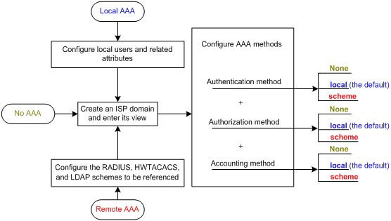
Table 4 AAA configuration task list
|
Task |
Remarks |
|
|
Required. Complete at least one task. |
||
|
Required. |
||
|
Optional. |
||
|
Required. Complete at least one task. |
||
|
Optional. |
||
|
Required. |
||
|
Optional. |
||
|
Optional. |
||
|
|
NOTE: To use AAA methods to control access of login users, you must configure the authentication-mode command. For more information, see Fundamentals Configuration Guide. |
Configuring AAA schemes
Configuring local users
To implement local AAA, you must create local users and configure user attributes on the device. The local users and attributes are stored in the local user database on the device. A local user is uniquely identified by a username. Configurable local user attributes are as follows:
· Service type.
Services that the user can use. Local authentication checks the service types of a local user. If none of the service types is available, the user cannot pass authentication.
Service types include FTP, LAN access, portal, PPP, SSH, Telnet, terminal, and Web. Support for the PPP service depends on the device model. For more information, see About the H3C Access Controllers Configuration Guides.
· User state.
Indicates whether or not a local user can request network services. There are two user states: active and blocked. A user in active state can request network services, but a user in blocked state cannot.
· Maximum number of users using the same local user account.
Indicates how many users can use the same local user account for local authentication.
· Validity time and expiration time.
Indicates the validity time and expiration time of a local user account. A user must use a valid local user account to pass local authentication. For temporary network access needs, you can create a guest account and specify a validity time and an expiration time for the account.
· User group.
Each local user belongs to a local user group and has all attributes of the group, such as the password control attributes and authorization attributes. For more information about local user group, see "Configuring user group attributes."
· Password control attributes.
Password control attributes help control the security of local users' passwords. Password control attributes include password aging time, minimum password length, and password composition policy.
You can configure a password control attribute in system view, user group view, or local user view, and you can make the attribute effective for all local users, all local users in a group, or only the local user. A password control attribute with a smaller effective range has a higher priority. For more information about password management and global password configuration, see "Configuring password control." For more information about password control commands, see Security Command Reference.
· Binding attributes.
Binding attributes control the scope of users, and are checked during local authentication of a user. If the attributes of a user do not match the binding attributes configured for the local user account, the user cannot pass authentication. Binding attributes include the ISDN calling number, IP address, access port, MAC address, and native VLAN.
· Authorization attributes.
Authorization attributes indicate the user's rights after it passes local authentication. Authorization attributes include the ACL, PPP callback number, idle cut function, user level, user role, user profile, VLAN, and FTP/SFTP work directory. For more information about authorization attributes, see "Configuring local user attributes."
Every configurable authorization attribute has its definite application environments and purposes. When you configure authorization attributes for a local user, consider which attributes are needed and which are not. For example, for PPP users, you do not need to configure the work directory attribute.
You can configure an authorization attribute in user group view or local user view to make the attribute effective for all local users in the group or for only the local user. The setting of an authorization attribute in local user view takes precedence over that in user group view.
Local user configuration task list
|
Task |
Remarks |
|
Required. |
|
|
Optional. |
|
|
Optional. |
|
|
Displaying and maintaining local users and local user groups |
Optional. |
Configuring local user attributes
Follow these guidelines when you configure local user attributes:
· When you use the password-control enable command to globally enable the password control feature, local user passwords are not displayed. At the same time, you cannot use the password hash cipher command to configure passwords for local users.
· If the user interface authentication mode set by the authentication-mode command in user interface view is AAA (scheme), command access for the login user depends on the privilege level authorized to the user. If the user interface authentication mode is password (password) or no authentication (none), command access for the login user depends on the level configured for the user interface by using the user privilege level command in user interface view. For an SSH user using public key authentication, command access for the login user depends on the level configured for the user interface. For more information about user interface authentication mode and user interface command level, see Fundamentals Configuration Guide.
· You can configure the user profile authorization attribute in local user view, user group view, and ISP domain view. The setting in local user view has the highest priority, and the setting in ISP domain view has the lowest priority. For more information about user profiles, see "Configuring a user profile."
To configure local user attributes:
|
Step |
Command |
Remarks |
|
1. Enter system view. |
system-view |
N/A |
|
2. Add a local user and enter local user view. |
local-user user-name |
By default, a local user named admin exists. |
|
3. Configure a password for the local user. |
password [ [ hash ] { cipher | simple } password ] |
Optional. A local user with no password configured passes authentication after providing the valid local username and attributes. To enhance security, configure a password for each local user. This command is not supported in FIPS mode. To configure passwords for local users, use the password control feature. |
|
4. Assign service types to the local user. |
service-type { ftp | lan-access | { ssh | telnet | terminal } * | portal | ppp | web } |
By default, no service is authorized to a local user. The ftp and telnet keywords are not supported in FIPS mode. Support for the ppp keyword depends on the device model. For more information, see About the H3C Access Controllers Command References. |
|
5. Place the local user to the active or blocked state. |
state { active | block } |
Optional. By default, a created local user is in active state and can request network services. |
|
6. Set the maximum number of concurrent users of the local user account. |
access-limit max-user-number |
Optional. By default, there is no limit to the maximum number of concurrent users of a local user account. The limit is effective only for local accounting, and is not effective for FTP users. |
|
7. Configure password control attributes for the local user. |
· Set the password aging time: · Set the minimum password length: · Configure the password composition policy: |
Optional. By default, the local user uses password control attributes of the user group to which the local user belongs, and uses the global setting for any password control attribute that is not configured in the user group. The global settings include a 90-day password aging time, a minimum password length of 10 characters, and at least one password composition type and at least one character required for each password composition type. In FIPS mode, the value for the type-number argument must be 4. |
|
8. Configure binding attributes for the local user. |
bind-attribute { call-number call-number [ : subcall-number ] | ip ip-address | location port slot-number subslot-number port-number | mac mac-address | vlan vlan-id } * |
Optional. By default, no binding attribute is configured for a local user. |
|
9. Configure authorization attributes for the local user. |
authorization-attribute { acl acl-number | callback-number callback-number | idle-cut minute | level level | session-timeout minutes | user-profile profile-name | user-role { guest | guest-manager } | vlan vlan-id | work-directory directory-name } * |
Optional. By default, no authorization attribute is configured for a local user. For PPP users, only acl, callback-number, idle-cut, session-timeout, and user-profile are supported. For LAN and portal users, only acl, idle-cut, user-profile, session-timeout, and vlan are supported. For SSH, terminal, and Web users, only level is supported. For FTP users, only level and work-directory are supported. For Telnet users, only level and user-role is supported. Support for the guest-manager keyword depends on the device model. For more information, see About the H3C Access Controllers Command References. |
|
10. Set the validity time of the local user. |
validity-date time |
Optional. Not set by default. |
|
11. Set the expiration time of the local user. |
expiration-date time |
Optional. Not set by default. Support for this feature depends on the device model. For more information, see About the H3C Access Controllers Configuration Guides. |
|
12. Assign the local user to a user group. |
group group-name |
Optional. By default, a local user belongs to the default user group system. |
Configuring user group attributes
User groups simplify local user configuration and management. A user group includes a group of local users and has a set of local user attributes. You can configure local user attributes for a user group to implement centralized user attributes management for the local users in the group. Configurable user attributes include password control attributes and authorization attributes.
By default, every new local user belongs to the default user group system and has all attributes of the group. To assign a local user to a different user group, use the group command in local user view.
To configure attributes for a user group:
|
Step |
Command |
Remarks |
|
1. Enter system view. |
system-view |
N/A |
|
2. Create a user group and enter user group view. |
user-group group-name |
N/A |
|
3. Configure password control attributes for the user group. |
· Set the password aging time: · Set the minimum password length: · Configure the password composition policy: |
Optional. By default, the user group uses global settings, including a 90-day password aging time, a minimum password length of 10 characters, and at least one password composition type and at least one character required for each password composition type. In FIPS mode, the value for the type-number argument must be 4. |
|
4. Configure authorization attributes for the user group. |
authorization-attribute { acl acl-number | callback-number callback-number | idle-cut minute | level level | session-timeout minutes | user-profile profile-name | vlan vlan-id | work-directory directory-name } * |
Optional. By default, no authorization attribute is configured for a user group. |
|
5. Set the guest attribute for the user group. |
group-attribute allow-guest |
Optional. By default, the guest attribute is not set for a user group, and guest users created by a guest manager through the Web interface cannot join the group. |
Configuring fast authentication for local portal users
This feature provides fast authentication for local portal users that access the network frequently.
After a local portal user passes portal authentication, the device creates a MAC binding entry that binds the user MAC address with the user authentication account. Before the MAC binding entry ages out, the user can directly use the MAC address to come online again if the user passes MAC authentication. No portal authentication is performed on the user.
This feature takes effect on local portal users whose service types also include the LAN access service.
To configure fast authentication for local portal users:
|
Step |
Command |
Remarks |
|
1. Enter system view. |
system-view |
N/A |
|
2. Enter local portal user view. |
local-user user-name |
N/A |
|
3. Enable fast authentication for the local portal user. |
fast-authentication enable |
By default, fast authentication is disabled for a local portal user. |
|
4. Specify the user MAC address for fast authentication. |
fast-authentication mac-address mac-address |
By default, the MAC address of a local portal user is not specified for fast authentication. |
|
5. Set the aging time of the MAC binding entry for the local portal user. |
fast-authentication aging aging-value |
Optional. By default, the aging time of the MAC binding entry for a local portal user is 12 hours. |
Displaying and maintaining local users and local user groups
|
Task |
Command |
Remarks |
|
Display local user information. |
display local-user [ idle-cut { disable | enable } | service-type { ftp | lan-access | portal | ppp | ssh | telnet | terminal | web } | state { active | block } | user-name user-name | vlan vlan-id ] [ | { begin | exclude | include } regular-expression ] |
Available in any view. The ftp and telnet keywords are not supported in FIPS mode. Support for the ppp keyword depends on the device model. For more information, see About the H3C Access Controllers Command References. |
|
Display the user group configuration. |
display user-group [ group-name ] [ | { begin | exclude | include } regular-expression ] |
Available in any view. |
Configuring RADIUS schemes
A RADIUS scheme specifies the RADIUS servers that the device can work with and defines a set of parameters that the device uses to exchange information with the RADIUS servers. For example, there might be authentication/authorization servers and accounting servers, or primary servers and secondary servers. The parameters include the IP addresses of the servers, the shared keys, and the RADIUS server type.
RADIUS scheme configuration task list
|
Task |
Remarks |
|
Required. |
|
|
Required. |
|
|
Specifying the RADIUS accounting servers and the relevant parameters |
Optional. |
|
Optional. |
|
|
Optional. |
|
|
Optional. |
|
|
Setting the maximum number of RADIUS request transmission attempts |
Optional. |
|
Optional. |
|
|
Specifying the source IP address for outgoing RADIUS packets |
Optional. |
|
Specifying a backup source IP address for outgoing RADIUS packets |
Optional. |
|
Optional. |
|
|
Optional. |
|
|
Optional. |
|
|
Optional. |
|
|
Configuring interpretation of the RADIUS class attribute as CAR parameters |
Optional. |
|
Configuring the NAS-IP-Address attribute for RADIUS Access-Request packets |
Required on BAS ACs in a MAC-BAC network. |
|
Configuring the Account-Delay-Time attribute for RADIUS Accounting-Request packets |
Optional. |
|
Optional. This function is available only on BAS ACs in a MAC-BAC network. |
|
|
Optional. |
|
|
Optional. |
|
|
Optional. |
|
|
Optional. |
Creating a RADIUS scheme
Before you perform other RADIUS configurations, first create a RADIUS scheme and enter RADIUS scheme view. A RADIUS scheme can be referenced by multiple ISP domains at the same time.
To create a RADIUS scheme and enter RADIUS scheme view:
|
Step |
Command |
Remarks |
|
1. Enter system view. |
system-view |
N/A |
|
2. Create a RADIUS scheme and enter RADIUS scheme view. |
radius scheme radius-scheme-name |
By default, no RADIUS scheme is created. |
Specifying the RADIUS authentication/authorization servers
In RADIUS, user authorization information is piggybacked in authentication responses sent to RADIUS clients. It is neither allowed nor needed to specify a separate RADIUS authorization server.
You can specify one primary authentication/authorization server and up to 16 secondary authentication/authorization servers for a RADIUS scheme. When the primary server is not available, a secondary server is used. If redundancy is not required, specify only the primary server.
A RADIUS authentication/authorization server can function as the primary authentication/authorization server for one scheme and a secondary authentication/authorization server for another scheme at the same time.
You can enable the server status detection feature. With the feature, the device periodically sends an authentication request to check whether or not the target RADIUS authentication/authorization server is reachable. If the server can be reached, the device sets the status of the server to active. If the server cannot be reached, the device sets the status of the server to block. This feature promptly notifies authentication modules of latest server status information.
To specify RADIUS authentication/authorization servers for a RADIUS scheme:
|
Step |
Command |
Remarks |
|
1. Enter system view. |
system-view |
N/A |
|
2. Enter RADIUS scheme view. |
radius scheme radius-scheme-name |
N/A |
|
3. Specify RADIUS authentication/authorization servers. |
· Specify the primary RADIUS
authentication/authorization server: · Specify a secondary RADIUS authentication/authorization server: |
Configure at least one command. By default, no authentication/authorization server is specified. In FIPS mode, the shared key for secure RADIUS authentication/authorization communication must be at least eight characters that contain digits, uppercase letters, lowercase letters, and special characters, and must use 3DES for encryption and decryption. The IP addresses of the primary and secondary authentication/authorization servers for a scheme must be different. Otherwise, the configuration will fail. All servers for authentication/authorization and accounting, primary or secondary, must use IP addresses of the same IP version. |
Specifying the RADIUS accounting servers and the relevant parameters
You can specify one primary accounting server and up to 16 secondary accounting servers for a RADIUS scheme. When the primary server is not available, a secondary server is used. When redundancy is not required, specify only the primary server. A RADIUS accounting server can function as the primary accounting server for one scheme and a secondary accounting server for another scheme at the same time.
When the device receives a connection teardown request from a host or a connection teardown command from an administrator, it sends a stop-accounting request to the accounting server. When the maximum number of real-time accounting attempts is reached, the device disconnects users who have no accounting responses. You can enable buffering of non-responded stop-accounting requests to allow the device to buffer and resend a stop-accounting request until it receives a response. If the number of stop-accounting attempts reaches the upper limit, the device discards the buffered request.
If you delete an accounting server that is serving users, the device no longer sends real-time accounting requests or stop-accounting requests for the users to that server, or buffers the stop-accounting requests.
RADIUS does not support accounting for FTP users.
To specify RADIUS accounting servers and set relevant parameters for a scheme:
|
Step |
Command |
Remarks |
|
1. Enter system view. |
system-view |
N/A |
|
2. Enter RADIUS scheme view. |
radius scheme radius-scheme-name |
N/A |
|
3. Specify RADIUS accounting servers. |
· Specify the primary RADIUS accounting server: · Specify a secondary RADIUS accounting server: |
Configure at least one command. By default, no accounting server is specified. In FIPS mode, the shared key for secure RADIUS accounting communication must be at least eight characters that contain digits, uppercase letters, lowercase letters, and special characters, and must use 3DES for encryption and decryption. The IP addresses of the primary and secondary accounting servers must be different from each other. Otherwise, the configuration fails. All servers for authentication/authorization and accounting, primary or secondary, must use IP addresses of the same IP version. |
|
4. Set the maximum number of real-time accounting attempts. |
retry realtime-accounting retry-times |
Optional. The default setting is 5. Support for this feature depends on the device model. For more information, see About the H3C Access Controllers Configuration Guides. |
|
5. Enable buffering of stop-accounting requests to which no responses are received. |
stop-accounting-buffer enable |
Optional. Enabled by default. Support for this feature depends on the device model. For more information, see About the H3C Access Controllers Configuration Guides. |
|
6. Set the maximum number of stop-accounting attempts. |
retry stop-accounting retry-times |
Optional. The default setting is 500. |
Specifying the shared keys for secure RADIUS communication
The RADIUS client and RADIUS server use the MD5 algorithm and a shared key pair for packet authentication and password encryption to secure communication.
A shared key configured in RADIUS scheme view applies to all servers of the specified type (accounting or authentication) in that scheme, and has a lower priority than those configured for individual RADIUS servers.
To specify a shared key for secure RADIUS communication:
|
Step |
Command |
Remarks |
|
1. Enter system view. |
system-view |
N/A |
|
2. Enter RADIUS scheme view. |
radius scheme radius-scheme-name |
N/A |
|
3. Specify a shared key for secure RADIUS authentication/authorization or accounting communication. |
key { accounting | authentication } [ cipher | simple ] key |
By default, no shared key is specified. The shared key configured on the device must be the same as that configured on the RADIUS server. In FIPS mode, the shared key must be at least eight characters that contain digits, uppercase letters, lowercase letters, and special characters. |
Setting the username format and traffic statistics units
A username is typically in the format userid@isp-name, where isp-name represents the user's ISP domain name. By default, the ISP domain name is included in a username. However, older RADIUS servers might not recognize usernames that contain the ISP domain names. In this case, you can configure the device to remove the domain name from each username to be sent.
The device periodically sends accounting updates to RADIUS accounting servers to report the traffic statistics of online users. For normal and accurate traffic statistics, make sure that the units for data flows and data packets on the device are consistent with units on the RADIUS server.
To set the username format and the traffic statistics units for a RADIUS scheme:
|
Step |
Command |
Remarks |
|
1. Enter system view. |
system-view |
N/A |
|
2. Enter RADIUS scheme view. |
radius scheme radius-scheme-name |
N/A |
|
3. Set the format for usernames sent to the RADIUS servers. |
user-name-format { keep-original | with-domain | without-domain } |
Optional. By default, the ISP domain name is included in a username. Do not apply the RADIUS scheme to more than one ISP domain if you have configured the user-name-format without-domain command for that RADIUS scheme. Otherwise, users in different ISP domains are considered the same user if they use the same username. For level switching authentication, user-name-format keep-original and user-name-format without-domain commands all produce the same result to remove ISP domain names from usernames sent to the RADIUS server. |
|
4. Specify the unit for data flows or packets sent to the RADIUS servers. |
data-flow-format { data { byte | giga-byte | kilo-byte | mega-byte } | packet { giga-packet | kilo-packet | mega-packet | one-packet } }* |
Optional. The default unit is byte for data flows and one-packet for data packets. |
Setting the supported RADIUS server type
The supported RADIUS server type determines the type of the RADIUS protocol that the device uses to communicate with the RADIUS server:
· Standard—Uses the standard RADIUS protocol, compliant to RFC 2865 and RFC 2866 or later.
· Extended—Uses the H3C proprietary RADIUS protocol.
When the RADIUS server runs on IMC, you must set the RADIUS server type to extended. When the RADIUS server runs third-party RADIUS server software, either RADIUS server type applies.
Changing the RADIUS server type will restore the units for data flows and data packets that are sent to the RADIUS server to be the defaults.
To set the RADIUS server type:
|
Step |
Command |
Remarks |
|
1. Enter system view. |
system-view |
N/A |
|
2. Enter RADIUS scheme view. |
radius scheme radius-scheme-name |
N/A |
|
3. Set the RADIUS server type. |
server-type { extended | standard } |
Optional. The default RADIUS server type is standard. |
Setting the maximum number of RADIUS request transmission attempts
RADIUS uses UDP packets to transfer data. Because UDP communication is not reliable, RADIUS uses a retransmission mechanism to improve reliability. If a NAS sends a RADIUS request to a RADIUS server but receives no response before the response timeout timer (defined by the timer response-timeout command) expires, the NAS retransmits the request. If the number of transmission attempts exceeds the specified limit but the NAS does not receive a response, it tries to communicate with other RADIUS servers in active state. If no other servers are in active state at the time, the NAS considers the authentication or accounting attempt a failure. For more information about RADIUS server states, see "Setting the status of RADIUS servers."
The maximum number of transmission attempts of RADIUS packets multiplied by the RADIUS server response timeout period cannot be greater than 75 seconds. For more information about the RADIUS server response timeout timer, see "Setting RADIUS timers."
To set the maximum number of RADIUS request transmission attempts for a scheme:
|
Step |
Command |
Remarks |
|
1. Enter system view. |
system-view |
N/A |
|
2. Enter RADIUS scheme view. |
radius scheme radius-scheme-name |
N/A |
|
3. Set the maximum number of RADIUS request transmission attempts. |
retry retry-times |
Optional. The default setting is 3. |
Setting the status of RADIUS servers
To control the AAA servers with which the device communicates when the current servers are no longer available, set the status of RADIUS servers to blocked or active. You can specify one primary RADIUS server and multiple secondary RADIUS servers, with the secondary servers functioning as the backup of the primary servers. Typically, the device chooses servers based on these rules:
· When the primary server is in active state, the device communicates with the primary server.
If the primary server fails, the device changes the server's status to blocked, starts a quiet timer for the server, and tries to communicate with a secondary server in active state (a secondary server configured earlier has a higher priority).
If the secondary server is unreachable, the device changes the server's status to blocked, starts a quiet timer for the server, and continues to check the next secondary server in active state. This search process continues until the device finds an available secondary server or has checked all secondary servers in active state.
If the quiet timer of a server expires or an authentication or accounting response is received from the server, the status of the server automatically changes back to active, but the device does not check the server again during the authentication or accounting process.
If no server is found reachable during one search process, the device considers the authentication or accounting attempt a failure.
· Once the accounting process of a user starts, the device continues to send the user's real-time accounting requests and stop-accounting requests to the same accounting server.
· If you remove the accounting server, real-time accounting requests and stop-accounting requests for the user are no longer delivered to the server.
· If you remove an authentication or accounting server in use, the communication of the device with the server will soon time out, and the device will look for a server in active state by checking the primary server first and then the secondary servers in the order they are configured.
· When the primary server and secondary servers are all in blocked state, the device communicates with the primary server. If the primary server is available, its status changes to active. Otherwise, its status remains to be blocked.
· If one server is in active state and all the others are in blocked state, the device only tries to communicate with the server in active state, even if the server is unavailable.
· After receiving an authentication/accounting response from a server, the device changes the status of the server identified by the source IP address of the response to active if the current status of the server is blocked.
The device does not change the status of an unreachable authentication or accounting server if the server quiet timer is set to 0. Instead, the device keeps the server status as active and sends authentication or accounting packets to another server in active state, so subsequent authentication or accounting packets can still be sent to that server. For more information about the server quiet timer, see "Setting RADIUS timers."
By default, the device sets the status of all RADIUS servers to active. In some situations, you might need to change the status of a server. For example, if a server fails, you can change the status of the server to blocked to avoid communication attempts to the server.
To set the status of RADIUS servers in a RADIUS scheme:
|
Step |
Command |
Remarks |
|
1. Enter system view. |
system-view |
N/A |
|
2. Enter RADIUS scheme view. |
radius scheme radius-scheme-name |
N/A |
|
3. Set the RADIUS server status. |
· Set the status of the primary RADIUS
authentication/authorization server: · Set the status of the primary RADIUS
accounting server: · Set the status of a secondary RADIUS
authentication/authorization server: · Set the status of a secondary RADIUS
accounting server: |
Optional. By default, all servers in the RADIUS scheme are in active state. The server status set by the state command cannot be saved to the configuration file. After the device restarts, the status of each server is restored to active. |
|
4. (Optional) Display the states of the servers. |
display radius scheme |
N/A |
Specifying the source IP address for outgoing RADIUS packets
The source IP address of RADIUS packets that a NAS sends must match the IP address of the NAS configured on the RADIUS server. A RADIUS server identifies a NAS by its IP address. Upon receiving a RADIUS packet, a RADIUS server checks whether the source IP address of the packet is the IP address of any managed NAS. If it is, the server processes the packet. If it is not, the server drops the packet.
The source address of outgoing RADIUS packets is typically the IP address of an egress interface on the NAS to communicate with the RADIUS server. However, in some situations, you must change the source IP address.
You can specify a source IP address for outgoing RADIUS packets for a specific RADIUS scheme or all RADIUS schemes. Before sending a RADIUS packet, the NAS selects a source IP address in the following order:
1. The source IP address specified for the RADIUS scheme.
2. The source IP address specified in system view.
3. The IP address of the outbound interface specified by the route.
To specify a source IP address for all RADIUS schemes:
|
Step |
Command |
Remarks |
|
1. Enter system view. |
system-view |
N/A |
|
2. Specify a source IP address for outgoing RADIUS packets. |
radius nas-ip { ip-address | ipv6 ipv6-address } |
By default, the IP address of the outbound interface is used as the source IP address. |
To specify a source IP address for a specific RADIUS scheme:
|
Step |
Command |
Remarks |
|
1. Enter system view. |
system-view |
N/A |
|
2. Enter RADIUS scheme view. |
radius scheme radius-scheme-name |
N/A |
|
3. Specify a source IP address for outgoing RADIUS packets. |
nas-ip { ip-address | ipv6 ipv6-address } |
By default, the IP address of the outbound interface is used as the source IP address. |
Specifying a backup source IP address for outgoing RADIUS packets
Support for this feature depends on the device model. For more information, see About the H3C Access Controllers Configuration Guides.
The backup source IP address specified for outgoing RADIUS packets takes effect only when stateful failover is configured, and it must be the source IP address for outgoing RADIUS packets that is configured on the standby device.
In a stateful failover scenario, the active device authenticates portal users by interacting with the RADIUS server, and synchronizes its online portal user information to the standby device through the backup link established between them. The standby device only receives and processes synchronization messages from the active device. However, if the active device fails, the RADIUS server cannot send RADIUS packets to the standby device because it does not have the IP address of the standby device.
To prevent problems, configure the source IP address for outgoing RADIUS packets on each device as the backup source IP address for outgoing RADIUS packets on the other device. With this configuration, the active device will send the source IP address for outgoing RADIUS packets configured on the standby device to the RADIUS server, so that the RADIUS server can send unsolicited RADIUS packets to the standby device.
You can specify a backup IP address for outgoing RADIUS packets for a specific RADIUS scheme or all RADIUS schemes. Before sending a RADIUS packet, the NAS selects a backup source IP address in the following order:
1. The backup source IP address specified for the RADIUS scheme.
2. The backup source IP address specified in system view.
If no backup source IP address is specified in the views, the NAS sends no backup source IP address to the server.
To specify a backup source IP address for all RADIUS schemes:
|
Step |
Command |
Remarks |
|
1. Enter system view. |
system-view |
N/A |
|
2. Specify a backup source IP address for outgoing RADIUS packets. |
radius nas-backup-ip ip-address |
Not specified by default. |
To specify a backup source IP address for a RADIUS scheme:
|
Step |
Command |
Remarks |
|
1. Enter system view. |
system-view |
N/A |
|
2. Enter RADIUS scheme view. |
radius scheme radius-scheme-name |
N/A |
|
3. Specify a backup source IP address for outgoing RADIUS packets. |
nas-backup-ip ip-address |
Not specified by default. |
Setting RADIUS timers
The device uses the following types of timers to control communication with a RADIUS server:
· Server response timeout timer (response-timeout)—Defines the RADIUS request retransmission interval. After sending a RADIUS request (authentication/authorization or accounting request), the device starts the server response timeout timer. If the device receives no response from the RADIUS server before the timer expires, it resends the request.
· Server quiet timer (quiet)—Defines the duration to keep an unreachable server in blocked state. If one server is not reachable, the device changes the server's status to blocked, starts this timer for the server, and tries to communicate with another server in active state. After the server quiet timer expires, the device changes the status of the server back to active.
· Real-time accounting timer (realtime-accounting)—Defines the interval for the device to send real-time accounting packets to the RADIUS accounting server for online users. To implement real-time accounting, the device must periodically send real-time accounting packets to the accounting server for online users.
Follow these guidelines when you set RADIUS timers:
· For the same type of users, the maximum number of transmission attempts multiplied by the RADIUS server response timeout period must be less than the client connection timeout time and cannot exceed 75 seconds. Otherwise, stop-accounting messages cannot be buffered, and the primary/secondary server switchover cannot take place. For example, the product of the two parameters must be less than 10 seconds for voice users and less than 30 seconds for Telnet users, because the client connection timeout period for voice users is 10 seconds and that for Telnet users is 30 seconds.
· When you configure the maximum number of RADIUS packet transmission attempts and the RADIUS server response timeout timer, consider the number of secondary servers. If the retransmission process takes too long, the client connection in the access module may time out while the device is trying to find an available server. For more information about the maximum number of RADIUS packet transmission attempts, see "Setting the maximum number of RADIUS request transmission attempts."
· When a number of secondary servers are configured, the client connections of access modules that have a short client connection timeout period may still be timed out during initial authentication or accounting, even if the packet transmission attempt limit and server response timeout period are configured with small values. In this case, the next authentication or accounting attempt can succeed because the device has set the status of the unreachable servers to blocked and the amount of time for finding a reachable server has been shortened.
· Properly set the server quiet timer. Too short a quiet timer can result in frequent authentication or accounting failures because the device has to repeatedly attempt to communicate with an unreachable server that is in active state.
To set RADIUS timers:
|
Step |
Command |
Remarks |
|
1. Enter system view. |
system-view |
N/A |
|
2. Enter RADIUS scheme view. |
radius scheme radius-scheme-name |
N/A |
|
3. Set the RADIUS server response timeout timer. |
timer response-timeout seconds |
Optional. The default RADIUS server response timeout timer is 3 seconds. |
|
4. Set the server quiet timer. |
timer quiet minutes |
Optional. The default server quiet timer is 5 minutes. |
|
5. Set the real-time accounting interval. |
timer realtime-accounting minutes |
Optional. The default real-time accounting interval is 12 minutes. Support for this feature depends on the device model. For more information, see About the H3C Access Controllers Configuration Guides. |
Configuring RADIUS accounting-on
The accounting-on feature enables the device to send an accounting-on packet to the RADIUS server after it reboots so the server can log out users who logged in through the device before the reboot. Without this feature, users who were online before the reboot cannot log in again after the reboot, because the RADIUS server would consider them to be online already.
If the device receives no response to the accounting-on packet, it re-sends the packet to the RADIUS server at a particular interval for the specified number of times.
The accounting-on feature must work with the H3C IMC network management system.
To configure the accounting-on feature for a RADIUS scheme:
|
Step |
Command |
Remarks |
|
1. Enter system view. |
system-view |
N/A |
|
2. Enter RADIUS scheme view. |
radius scheme radius-scheme-name |
N/A |
|
3. Enable accounting-on and configure parameters. |
accounting-on enable [ interval seconds | send send-times ] * |
Disabled by default. The default interval is 3 seconds, and the default number of send-times is 50. |
Configuring the IP address of the security policy server
The security policy server is the management and control center for Endpoint Admission Defense (EAD). The NAS checks the validity of received control packets and accepts only control packets from known servers. To use a security policy server that is independent of the AAA servers, you must configure the IP address of the security policy server on the NAS. To implement all EAD functions, configure both the IP address of the security policy server and the IP address of the IMC Platform on the NAS.
To configure the IP address of the security policy server for a scheme:
|
Step |
Command |
Remarks |
|
1. Enter system view. |
system-view |
N/A |
|
2. Enter RADIUS scheme view. |
radius scheme radius-scheme-name |
N/A |
|
3. Specify a security policy server. |
security-policy-server ip-address |
No security policy server is specified by default. You can specify up to eight security policy servers for a RADIUS scheme. |
Enabling the RADIUS offload feature
RADIUS servers that do not support EAP authentication cannot process EAP packets. To work with these servers, the device must process EAP packets from EAP clients before forwarding them to the servers. The RADIUS offload feature enables the device to process EAP packets.
The RADIUS offload feature must work with the local EAP authentication server as follows:
1. After receiving EAP packets from an EAP client, the local EAP authentication server interacts with the client, encapsulates the authentication information of the client into the RADIUS MS-CHAPv2 attribute and sends the attribute in a RADIUS authentication request to the RADIUS server.
2. When a RADIUS server receives the requests, it resolves the authentication information in the request, performs authentication, and then encapsulates and sends the authentication result in a RADIUS packet to the local EAP authentication server.
To deploy the RADIUS offload feature, complete the following tasks on the device:
· Configure the local EAP authentication server to use PEAP-MSCHAPv2 as the EAP authentication method. For more information about the configuration, see "Configuring local EAP authentication."
· Enable the EAP offload feature for the RADIUS schemes.
To enable the EAP offload feature:
|
Step |
Command |
Remarks |
|
1. Enter system view. |
system-view |
N/A |
|
2. Enter RADIUS scheme view. |
radius scheme radius-scheme-name |
N/A |
|
3. Enable the EAP offload feature. |
eap offload method peap-mschapv2 |
Disabled by default. |
Configuring interpretation of the RADIUS class attribute as CAR parameters
This task is required when the RADIUS server supports assigning CAR parameters through the class attribute.
According to RFC 2865, a RADIUS server assigns the RADIUS class attribute (attribute 25) to a RADIUS client. However, the RFC does not require the RADIUS client to interpret the attribute and only requires the RADIUS client to send the attribute to the accounting server on an "as is" basis. When RADIUS servers use the class attribute to deliver the assigned CAR parameters, the device must interpret the attribute as the CAR parameters to implement user-based traffic monitoring and controlling.
To configure the device to interpret the RADIUS class attribute as CAR parameters:
|
Step |
Command |
Remarks |
|
1. Enter system view. |
system-view |
N/A |
|
2. Enter RADIUS scheme view. |
radius scheme radius-scheme-name |
N/A |
|
3. Interpret the class attribute as CAR parameters. |
attribute 25 car |
By default, RADIUS attribute 25 is not interpreted as CAR parameters. |
Configuring the NAS-IP-Address attribute for RADIUS Access-Request packets
A RADIUS server uses the NAS-IP-Address attribute (attribute number 4) to uniquely identify a NAS.
In a MAC-BAC network, the master AC forwards all authentication requests to the RADIUS server for the BAS ACs it manages. Before a RADIUS Access-Request packet is forwarded, the source IP address of the packet is translated into the IP address of the master AC by the NAT feature. The NAS-IP-Address attribute in the packet must be consistent with the translated source IP address. Perform this task to modify the NAS-IP-Address attribute for RADIUS Access-Request packets on the BAS AC that initiates the request.
To configure the NAS-IP-Address attribute for RADIUS Access-Request packets on a BAS AC:
|
Step |
Command |
Remarks |
|
1. Enter system view. |
system-view |
N/A |
|
2. Enter RADIUS scheme view. |
radius scheme radius-scheme-name |
N/A |
|
3. Configure the NAS-IP-Address attribute for RADIUS Access-Request packets. |
attribute 4 ip-address |
By default, the NAS-IP-Address attribute takes the source IP address of these packets. |
Configuring the Account-Delay-Time attribute for RADIUS Accounting-Request packets
The Account-Delay-Time attribute (attribute number 41) in a RADIUS Accounting-Request packet indicates the transmission delay for the packet. Some RADIUS servers require the value of this attribute to be 0 while some RADIUS servers do not have this requirement. For the device to cooperate with different RADIUS servers, you can set the value of the Account-Delay-Time attribute in RADIUS Accounting-Request packets.
To configure the Account-Delay-Time attribute for RADIUS Accounting-Request packets:
|
Step |
Command |
Remarks |
|
1. Enter system view. |
system-view |
N/A |
|
2. Enter RADIUS scheme view. |
radius scheme radius-scheme-name |
N/A |
|
3. Configure the Account-Delay-Time attribute for RADIUS Accounting-Request packets. |
attribute 41 value |
By default, the value of the Account-Delay-Time attribute for a RADIUS Accounting-Request packet is the actual transmission delay for the packet. |
Configuring the DAE server
Dynamic Authorization Extensions (DAE) to RADIUS can log off online users or change their authorization information. DAE uses the client/server mode, which includes the Dynamic Authorization Server (DAS) and the Dynamic Authorization Client (DAC).
In a MAC-BAC network, the master AC acts as the DAE proxy for the BAS ACs (DACs). When the master AC receives DAE packets from DACs, it verifies the Authenticator field in these packets. The master AC forwards packets to the NAS AC (DAS) only when they pass authentication.
To save bandwidth, configure the NAS ACs not to authenticate the DAE packets sent by the master AC.
To configure the DAE server:
|
Step |
Command |
Remarks |
|
1. Enter system view. |
system-view |
N/A |
|
2. Specify the UDP port to listen for and receive DAE packets. |
radius dynamic-author port listen-port |
Optional. By default, the UDP port is 3799. |
|
3. Specify the IP address of the DAC that can bypass DAE authentication. |
radius dynamic-author client trusted ip ip-address |
Optional. By default, the device verifies the Authenticator field for all received DAE packets. |
Enabling the trap function for RADIUS
With the trap function, the NAS sends a trap message when either of the following events occurs:
· The status of a RADIUS server changes. If the NAS receives no response to an accounting or authentication request before the specified maximum number of RADIUS request transmission attempts is exceeded, it considers the server unreachable, sets the status of the server to block, and sends a trap message. If the NAS receives a response from a RADIUS server that it considers unreachable, the NAS considers that the RADIUS server is reachable again, sets the status of the server to active, and sends a trap message.
· The ratio of failed transmission attempts to the total authentication request transmission attempts exceeds a threshold. The threshold ranges from 1% to 100% and defaults to 30%. The threshold can only be configured through the MIB.
Typically, the failure ratio is small. If a trap message is triggered because the failure ratio is higher than the threshold, troubleshoot the configuration on and the communication between the NAS and the RADIUS server.
To enable the trap function for RADIUS:
|
Step |
Command |
Remarks |
|
1. Enter system view. |
system-view |
N/A |
|
2. Enable the trap function for RADIUS. |
radius trap { accounting-server-down | authentication-error-threshold | authentication-server-down } |
Disabled by default. |
Enabling logging of RADIUS packets
You can enable the device to generate logs for RADIUS packets. Make sure the device has sufficient system resources.
To enable logging of RADIUS packets:
|
Step |
Command |
Remarks |
|
1. Enter system view. |
system-view |
N/A |
|
2. Enable logging of RADIUS packets. |
radius log packet |
Disabled by default. |
Enabling the RADIUS client service
To receive and send RADIUS packets, enable the RADIUS client service on the device. If RADIUS is not required, disable the RADIUS client service to avoid attacks that exploit RADIUS packets.
To enable the RADIUS client service:
|
Step |
Command |
Remarks |
|
1. Enter system view. |
system-view |
N/A |
|
2. Enable the RADIUS client service. |
radius client enable |
Optional. Enabled by default. |
Displaying and maintaining RADIUS
|
Task |
Command |
Remarks |
|
Display the configuration of RADIUS schemes. |
display radius scheme [ radius-scheme-name ] [ | { begin | exclude | include } regular-expression ] |
Available in any view. |
|
Display the RADIUS packet statistics. |
display radius statistics [ | { begin | exclude | include } regular-expression ] |
Available in any view. |
|
Display information about buffered stop-accounting requests for which no responses have been received. |
display stop-accounting-buffer { radius-scheme radius-scheme-name | session-id session-id | time-range start-time stop-time | user-name user-name } [ | { begin | exclude | include } regular-expression ] |
Available in any view. Support for this command depends on the device model. For more information, see About the H3C Access Controllers Command References. |
|
Clear RADIUS statistics. |
reset radius statistics |
Available in user view. |
|
Clear the buffered stop-accounting requests for which no responses have been received. |
reset stop-accounting-buffer { radius-scheme radius-scheme-name | session-id session-id | time-range start-time stop-time | user-name user-name } |
Available in user view. Support for this command depends on the device model. For more information, see About the H3C Access Controllers Command References. |
Configuring HWTACACS schemes
You cannot remove the HWTACACS schemes that are in use or change the IP addresses of the HWTACACS servers that are in use.
HWTACACS configuration task list
|
Task |
Remarks |
|
Required. |
|
|
Required. |
|
|
Optional. |
|
|
Specifying the HWTACACS accounting servers and the relevant parameters |
Optional. |
|
Specifying the shared keys for secure HWTACACS communication |
Required. |
|
Optional. |
|
|
Specifying the source IP address for outgoing HWTACACS packets |
Optional. |
|
Optional. |
|
|
Optional. |
Creating an HWTACACS scheme
The HWTACACS protocol is configured on a per-scheme basis. Before you perform other HWTACACS configurations, create an HWTACACS scheme and enter HWTACACS scheme view. You can configure up to 16 HWTACACS schemes.
You can delete an HWTACACS scheme only when it is not in use.
To create an HWTACACS scheme and enter HWTACACS scheme view:
|
Step |
Command |
Remarks |
|
1. Enter system view. |
system-view |
N/A |
|
2. Create an HWTACACS scheme and enter HWTACACS scheme view. |
hwtacacs scheme hwtacacs-scheme-name |
Not defined by default. |
Specifying the HWTACACS authentication servers
You can specify one primary authentication server and one secondary authentication server for an HWTACACS scheme. When the primary server is not available, the secondary server is used. If redundancy is not required, specify only the primary server.
An HWTACACS server can function as the primary authentication server of one scheme and as the secondary authentication server of another scheme at the same time. You cannot specify the same IP address as both the primary and the secondary authentication servers in a scheme.
You can remove an authentication server only when no active TCP connection for sending authentication packets is using it.
To specify HWTACACS authentication servers for an HWTACACS scheme:
|
Step |
Command |
Remarks |
|
1. Enter system view. |
system-view |
N/A |
|
2. Enter HWTACACS scheme view. |
hwtacacs scheme hwtacacs-scheme-name |
N/A |
|
3. Specify HWTACACS authentication servers. |
· Specify the primary HWTACACS authentication
server: · Specify a secondary HWTACACS authentication server: |
Configure at least one command. No authentication server is specified by default. |
Specifying the HWTACACS authorization servers
You can specify one primary authorization server and one secondary authorization server for an HWTACACS scheme. When the primary server is not available, the secondary server is used. If redundancy is not required, specify only the primary server.
An HWTACACS server can function as the primary authorization server of one scheme and as the secondary authorization server of another scheme at the same time. You cannot specify the same IP address as both the primary and the secondary authorization servers in a scheme.
You can remove an authorization server only when no active TCP connection for sending authorization packets is using it.
To specify HWTACACS authorization servers for an HWTACACS scheme:
|
Step |
Command |
Remarks |
|
1. Enter system view. |
system-view |
N/A |
|
2. Enter HWTACACS scheme view. |
hwtacacs scheme hwtacacs-scheme-name |
N/A |
|
3. Specify HWTACACS authorization servers. |
· Specify the primary HWTACACS authorization
server: · Specify a secondary HWTACACS authorization server: |
Configure at least one command. No authorization server is specified by default. |
Specifying the HWTACACS accounting servers and the relevant parameters
You can specify one primary accounting server and one secondary accounting server for an HWTACACS scheme. When the primary server is not available, the secondary server is used. If redundancy is not required, specify only the primary server.
When the device receives a connection teardown request from a host or a connection teardown command from an administrator, it sends a stop-accounting request to the accounting server. You can enable buffering of non-responded stop-accounting requests to allow the device to buffer and resend a stop-accounting request until it receives a response or the number of stop-accounting attempts reaches the configured limit. When the number of stop-accounting attempts reaches the configured limit, the device discards the packet.
An HWTACACS server can function as the primary accounting server of one scheme and as the secondary accounting server of another scheme at the same time. You cannot specify the same IP address as both the primary and the secondary accounting servers in a scheme.
HWTACACS does not support accounting for FTP users.
You can remove an accounting server only when no active TCP connection for sending accounting packets is using it.
To specify HWTACACS accounting servers and set relevant parameters for an HWTACACS scheme:
|
Step |
Command |
Remarks |
|
1. Enter system view. |
system-view |
N/A |
|
2. Enter HWTACACS scheme view. |
hwtacacs scheme hwtacacs-scheme-name |
N/A |
|
3. Specify HWTACACS accounting servers. |
· Specify the primary HWTACACS accounting server: · Specify a secondary HWTACACS accounting server: |
Configure at least one command. No accounting server is specified by default. |
|
4. Enable buffering of stop-accounting requests to which no responses are received. |
stop-accounting-buffer enable |
Optional. Enabled by default. |
|
5. Set the maximum number of stop-accounting attempts. |
retry stop-accounting retry-times |
Optional. The default setting is 100. |
Specifying the shared keys for secure HWTACACS communication
The HWTACACS client and HWTACACS server use the MD5 algorithm and a shared key pair for password encryption.
To specify a shared key for secure HWTACACS communication:
|
Step |
Command |
Remarks |
|
1. Enter system view. |
system-view |
N/A |
|
2. Enter HWTACACS scheme view. |
hwtacacs scheme hwtacacs-scheme-name |
N/A |
|
3. Specify a shared key for secure HWTACACS authentication, authorization, or accounting communication. |
key { accounting | authentication | authorization } [ cipher | simple ] key |
By default, no shared key is specified. The shared key configured on the device must be the same as the shared key configured on the HWTACACS server. In FIPS mode, the shared key for secure HWTACACS communication must be at least eight characters that contain digits, uppercase letters, lowercase letters, and special characters. |
Setting the username format and traffic statistics units
A username is typically in the format userid@isp-name, where isp-name represents the user's ISP domain name. By default, the ISP domain name is included in a username. However, some HWTACACS servers do not recognize usernames that contain the ISP domain names. In this case, you can configure the device to remove the domain name from each username to be sent.
The device periodically sends accounting updates to HWTACACS accounting servers to report the traffic statistics of online users. For normal and accurate traffic statistics, make sure that the units for data flows and for data packets on the device are consistent with the units configured on the HWTACACS servers.
To set the username format and the traffic statistics units for an HWTACACS scheme:
|
Step |
Command |
Remarks |
|
1. Enter system view. |
system-view |
N/A |
|
2. Enter HWTACACS scheme view. |
hwtacacs scheme hwtacacs-scheme-name |
N/A |
|
3. Set the format of usernames sent to the HWTACACS servers. |
user-name-format { keep-original | with-domain | without-domain } |
Optional. By default, the ISP domain name is included in a username. If an HWTACACS server does not support a username that includes the domain name, configure the device to remove the domain name before sending the username to the server. For level switching authentication, user-name-format keep-original and user-name-format without-domain commands make sure that usernames sent to the HWTACACS server do not include ISP domain names. |
|
4. Specify the unit for data flows or packets sent to the HWTACACS servers. |
data-flow-format { data { byte | giga-byte | kilo-byte | mega-byte } | packet { giga-packet | kilo-packet | mega-packet | one-packet } }* |
Optional. The default unit is byte for data flows and one-packet for data packets. |
Specifying the source IP address for outgoing HWTACACS packets
The source IP address of HWTACACS packets that a NAS sends must match the IP address of the NAS configured on the HWTACACS server. An HWTACACS server identifies a NAS by IP address. When the HWTACACS server receives a packet, it checks whether the source IP address of the packet is the IP address of a managed NAS. If it is, the server processes the packet. If it is not, the server drops the packet.
To communicate with the HWTACACS server, the source address of outgoing HWTACACS packets is typically the IP address of an egress interface on the NAS. However, in some situations, you must change the source IP address.
You can specify the source IP address for outgoing HWTACACS packets for a specific HWTACACS scheme or all HWTACACS schemes.
Before sending an HWTACACS packet, the NAS selects a source IP address in the following order:
1. The source IP address specified for the HWTACACS scheme.
2. The source IP address specified in system view.
3. The IP address of the outbound interface specified by the route.
To specify a source IP address for all HWTACACS schemes:
|
Step |
Command |
Remarks |
|
1. Enter system view. |
system-view |
N/A |
|
2. Specify a source IP address for outgoing HWTACACS packets. |
hwtacacs nas-ip ip-address |
By default, the IP address of the outbound interface is used as the source IP address. |
To specify a source IP address for a specific HWTACACS scheme:
|
Step |
Command |
Remarks |
|
1. Enter system view. |
system-view |
N/A |
|
2. Enter HWTACACS scheme view. |
hwtacacs scheme hwtacacs-scheme-name |
N/A |
|
3. Specify a source IP address for outgoing HWTACACS packets. |
nas-ip ip-address |
By default, the IP address of the outbound interface is used as the source IP address. |
Setting HWTACACS timers
The device uses the following timers to control communication with an HWTACACS server:
· Server response timeout timer (response-timeout)—Defines the HWTACACS request retransmission interval. After sending an HWTACACS request (authentication, authorization, or accounting request), the device starts the server response timeout timer. If the device does not receive a response from the server before the timer expires, it resends the request.
· Primary server quiet timer (quiet)—Defines the duration to keep an unreachable primary server in blocked state. If a primary server is not reachable, the device changes the server's status to blocked, starts this timer for the server, and tries to communicate with the secondary server if the secondary server is configured and in active state. After the primary server quiet timer expires, the device changes the status of the primary server back to active.
To set HWTACACS timers:
|
Step |
Command |
Remarks |
|
1. Enter system view. |
system-view |
N/A |
|
2. Enter HWTACACS scheme view. |
hwtacacs scheme hwtacacs-scheme-name |
N/A |
|
3. Set the HWTACACS server response timeout timer. |
timer response-timeout seconds |
Optional. The default HWTACACS server response timeout timer is 5 seconds. |
|
4. Set the quiet timer for the primary server. |
timer quiet minutes |
Optional. The default quiet timer for the primary server is 5 minutes. |
Displaying and maintaining HWTACACS
|
Task |
Command |
Remarks |
|
Display the configuration or statistics of HWTACACS schemes. |
display hwtacacs [ hwtacacs-server-name [ statistics ] ] [ | { begin | exclude | include } regular-expression ] |
Available in any view. |
|
Display information about buffered stop-accounting requests for which no responses have been received. |
display stop-accounting-buffer hwtacacs-scheme hwtacacs-scheme-name [ | { begin | exclude | include } regular-expression ] |
Available in any view. |
|
Clear HWTACACS statistics. |
reset hwtacacs statistics { accounting | all | authentication | authorization } |
Available in user view. |
|
Clear buffered stop-accounting requests that do not get responses. |
reset stop-accounting-buffer hwtacacs-scheme hwtacacs-scheme-name |
Available in user view. |
Configuring LDAP schemes
LDAP configuration task list
|
Task |
Remarks |
|
Required. |
|
|
Required. |
|
|
Optional. |
|
|
Optional. |
|
|
Optional. |
|
|
Optional. |
|
|
Required. |
|
|
Required. |
|
|
Optional. |
|
|
Optional. |
Creating an LDAP scheme
Before performing other LDAP configurations, you must create an LDAP scheme and enter LDAP scheme view. You can configure up to 16 LDAP schemes. An LDAP scheme can be referenced by multiple ISP domains, and can be deleted only when it is not referenced.
To create an LDAP scheme and enter LDAP scheme view:
|
Step |
Command |
Remarks |
|
1. Enter system view. |
system-view |
N/A |
|
2. Create an LDAP scheme and enter LDAP scheme view. |
ldap scheme ldap-scheme-name |
By default, no LDAP scheme is present. |
Specifying the LDAP authentication server
Changing the IP address and port number of the LDAP authentication server only affects LDAP authentication processes that occur after your change.
To specify the LDAP authentication server:
|
Step |
Command |
Remarks |
|
1. Enter system view. |
system-view |
N/A |
|
2. Enter LDAP scheme view. |
ldap scheme ldap-scheme-name |
N/A |
|
3. Specify the LDAP authentication server. |
authentication-server ip-address [ port-number ] |
Not specified by default. |
Specifying the LDAP authorization server
Changing the IP address and port number of the LDAP authorization server only affects LDAP authorization processes that occur after your change.
To specify the LDAP authorization server:
|
Step |
Command |
Remarks |
|
1. Enter system view. |
system-view |
N/A |
|
2. Enter LDAP scheme view. |
ldap scheme ldap-scheme-name |
N/A |
|
3. Specify the LDAP authorization server. |
authorization-server ip-address [ port-number ] |
Not specified by default. |
Specifying the LDAP version
The device supports LDAPv2 and LDAPv3. A Microsoft LDAP server supports only LDAPv3.
To specify the LDAP version:
|
Step |
Command |
Remarks |
|
1. Enter system view. |
system-view |
N/A |
|
2. Enter LDAP scheme view. |
ldap scheme ldap-scheme-name |
N/A |
|
3. Specify the LDAP version. |
protocol-version { v2 | v3 } |
Optional. LDAPv3 is used by default. |
Specifying the LDAP server type
The device supports LDAP servers by IBM, Microsoft, and Sun.
To specify the type of the LDAP server:
|
Step |
Command |
Remarks |
|
1. Enter system view. |
system-view |
N/A |
|
2. Enter LDAP scheme view. |
ldap scheme ldap-scheme-name |
N/A |
|
3. Specify the LDAP server type. |
server-type { ibm | microsoft | sun } |
Optional. The default LDAP server type is microsoft. |
Setting the LDAP server timeout period
If the device sends a bind or search request to an LDAP server but does not receive a response from the server within the LDAP server timeout period, the device considers that the authentication or authorization request has timed out and tries the backup authentication or authorization method, if any. If no backup method is configured, the device considers the authentication or authorization attempt as a failure.
To set the LDAP server timeout period:
|
Step |
Command |
Remarks |
|
1. Enter system view. |
system-view |
N/A |
|
2. Enter LDAP scheme view. |
ldap scheme ldap-scheme-name |
N/A |
|
3. Set the LDAP server timeout period. |
server-timeout time-interval |
Optional. The default LDAP server timeout period is 10 seconds. |
Configuring administrator attributes
To configure the administrator DN and password for binding with the LDAP server during LDAP authentication:
|
Step |
Command |
Remarks |
|
1. Enter system view. |
system-view |
N/A |
|
2. Enter LDAP scheme view. |
ldap scheme ldap-scheme-name |
N/A |
|
3. Specify the administrator DN. |
login-dn dn-string |
Not specified by default. The administrator DN specified on the device must be consistent with the administrator DN specified on the LDAP server. |
|
4. Configure the administrator password. |
login-password [ cipher | simple ] password |
Not specified by default. |
Configuring LDAP user attributes
To authenticate a user, an LDAP client must establish a connection to the LDAP server, obtain the user DN, and use the user DN and the user's password to bind with the LDAP server. According to the LDAP DN search mechanism, an LDAP client sends search requests to the server based on the search policy determined by the LDAP user attributes of the LDAP client.
The LDAP user attributes include:
· Search base DN
· Search scope
· User group attribute
· Username attribute
· Username format
· User object class
If the user group attribute is configured on the LDAP server, the user group attribute setting on the device must match the setting on the LDAP server.
A user DN search starting from the root directory might take a long time if the LDAP server has many levels of directories. To improve search efficiency, you can change the start point by specifying the search base DN.
If the usernames configured on the LDAP server do not contain domain names, configure the device to remove domain names from the usernames to be sent to the LDAP server. Otherwise, configure the device to send usernames containing domain names to the LDAP server.
The Microsoft LDAP server defines a default user group attribute named memberOf. If the Microsoft LDAP server is used, the device obtains the user group by searching for the user DN.
The IBM LDAP server and Sun LDAP server have no default user group attribute, and you can configure a user group attribute by modifying the schema file on the LDAP server. If the IBM server or Sun server is used and there is no user-defined user group attribute, the device figures out the user group by checking each user group to see whether it contains the user DN. For more information about user group attribute configuration, see "Configuring LDAP group attributes."
To configure LDAP user attributes:
|
Step |
Command |
Remarks |
|
1. Enter system view. |
system-view |
N/A |
|
2. Enter LDAP scheme view. |
ldap scheme ldap-scheme-name |
N/A |
|
3. Specify the user search base DN. |
user-parameters search-base-dn base-dn |
Not specified by default. |
|
4. Specify the user search scope. |
user-parameters search-scope { all-level | single-level } |
Optional. The default user search scope is all-level. |
|
5. Specify the required user group attribute. |
user-parameters user-group-attribute attribute-name |
Optional. By default, no user group attribute is specified, and the default user group attribute defined on the LDAP server is used. |
|
6. Specify the username attribute. |
user-parameters user-name-attribute { name-attribute | cn | uid } |
Optional. The default username attribute is cn. |
|
7. Specify the username format. |
user-parameters user-name-format { with-domain | without-domain } |
Optional. The default username format is without-domain. |
|
8. Specify the user object class. |
user-parameters user-object-class object-class-name |
Optional. By default, no user object class is specified, and the default user object class on the LDAP server is used. The default user object class varies by device. |
Configuring LDAP group attributes
User authorization is implemented by searching user groups and obtaining authorization information. For a user group search, specify the search method and criteria (LDAP group attributes). Specifying group attributes is necessary for IBM and Sun LDAP servers. Because the user object class of Microsoft LDAP server contains user group attributes, specifying group attributes is unnecessary for Microsoft LDAP server. Configurable LDAP group attributes are as follows:
· Group name attribute
· Group object class
· Member name attribute
· Search base DN
· Search scope
Typically, the group object class and member name attribute take the default values defined by the server manufacturers. If no default values are specified or you want to customize them, you can use commands to configure the values.
A user group search starting from the root directory might take a long time if the LDAP server has many levels of directories. To improve search efficiency, you can change the start point by specifying the search base DN. Support for the group object class default and member name attribute default depends on the LDAP server manufacturers. IBM and Sun support the default group object class and member name attribute, but Microsoft does not have these defaults.
To configure LDAP group attributes:
|
Step |
Command |
Remarks |
|
1. Enter system view. |
system-view |
N/A |
|
2. Enter LDAP scheme view. |
ldap scheme ldap-scheme-name |
N/A |
|
3. Specify the search base DN for group search. |
group-parameters search-base-dn base-dn |
Not specified by default. |
|
4. Specify the search scope for group search. |
group-parameters search-scope { all-level | single-level } |
Optional. The default search scope for group search is all-level. |
|
5. Specify a user-defined group object class for group search. |
group-parameters group-object-class object-class-name |
Optional. Not specified by default. |
|
6. Specify the member name attribute for group search. |
group-parameters member-name-attribute attribute-name |
Optional. Not specified by default. |
|
7. Specify the group name attribute for group search. |
group-parameters group-name-attribute { name-attribute | cn | uid } |
Optional. The default group name attribute for group search is cn. |
Displaying and maintaining LDAP
|
Task |
Command |
Remarks |
|
Display the configuration of LDAP schemes. |
display ldap scheme [ scheme-name ] [ | { begin | exclude | include } regular-expression ] |
Available in any view. |
Configuring AAA methods for ISP domains
By default, the device uses local (default) AAA methods for users in an ISP domain. To use other AAA methods for them, configure the device to reference existing AAA schemes for the ISP domain. For information about configuring AAA schemes, see "Configuring RADIUS schemes," "Configuring HWTACACS schemes," and "Configuring LDAP schemes."
To use local authentication for users in an ISP domain, first configure local user accounts on the device (see "Configuring local user attributes").
Creating an ISP domain
In a networking scenario with multiple ISPs, the device can connect users from different ISPs. Different ISP users can have different user attributes (such as username and password structures), different service types, and different rights. To manage these ISP users, you need to create ISP domains and then configure AAA methods and domain attributes for each ISP domain.
The device can accommodate up to 16 ISP domains, including the system-defined ISP domain system. You can specify one ISP domain as the default domain.
On the device, each user belongs to an ISP domain. If a user provides no ISP domain name at login, the device considers the user belongs to the default ISP domain.
The device chooses an authentication domain for each user in the following order:
· The authentication domain specified for the access module
· The ISP domain in the username
· The default ISP domain of the device
· The ISP domain specified for users with unknown domain names
If all the domains are unavailable, user authentication will fail.
|
|
NOTE: Support for the authentication domain configuration depends on the access module. You can specify an authentication domain for 802.1X, portal, or MAC address authentication. |
To create an ISP domain:
|
Step |
Command |
Remarks |
|
1. Enter system view. |
system-view |
N/A |
|
2. Create an ISP domain and enter ISP domain view. |
domain isp-name |
N/A |
|
3. Return to system view. |
quit |
N/A |
|
4. Specify the default ISP domain. |
domain default enable isp-name |
Optional. By default, the default ISP domain is the system-defined ISP domain system. To delete the ISP domain that is functioning as the default ISP domain, you must change it to a non-default ISP domain by using the undo domain default enable command. |
|
5. Specify an ISP domain for users with unknown domain names. |
domain if-unknown isp-name |
Optional. By default, no ISP domain is specified for users with unknown domain names. |
Configuring ISP domain attributes
In an ISP domain, you can configure the following attributes:
· Domain status—By placing the ISP domain to the active or blocked state, you allow or deny network service requests from users in the domain.
· Maximum number of online users—The device controls the number of online users in a domain to ensure reliable system performance and services.
· Idle cut—Enables the device to check the traffic of each online user in the domain at the idle timeout interval, and to log out any user in the domain whose traffic during the idle timeout period is less than the specified minimum traffic.
· Self-service server location—Allows users to access the self-service server to manage their own accounts and passwords. A self-service RADIUS server running on IMC is required for the self-service server location function to work.
· IP address pool for allocating addresses to PPP users—The device assigns IP addresses from the pool to PPP users in the domain.
· Default authorization user profile—If a user passes authentication but is not authorized with a user profile, the device authorizes the default user profile of the ISP domain to the user and restricts the user's behavior based on the profile. For more information about user profiles, see "Configuring a user profile."
· Authorization session time—The device logs off a user when the session timeout timer of the user expires.
· User online duration including idle timeout period—If a user goes offline due to connection failure or malfunction, the user's online duration sent to the server includes the idle timeout period. The online duration that is generated on the server is longer than the actual online duration of the user.
An ISP domain attribute applies to all users in the domain.
To configure ISP domain attributes:
|
Step |
Command |
Remarks |
|
1. Enter system view. |
system-view |
N/A |
|
2. Enter ISP domain view. |
domain isp-name |
N/A |
|
3. Place the ISP domain to the active or blocked state. |
state { active | block } |
Optional. By default, an ISP domain is in active state, and users in the domain can request network services. |
|
4. Specify the maximum number of online users in the ISP domain. |
access-limit enable max-user-number |
Optional. No limit is specified by default. |
|
5. Configure the idle cut function. |
idle-cut enable minute [ flow ] |
Optional. Disabled by default. This command is effective only for LAN, portal, and PPP users. In a portal stateful failover scenario, set the idle cut interval to be greater than 5 minutes to make sure data of online users can be backed up. |
|
6. Enable the self-service server location function and specify the URL of the self-service server. |
self-service-url enable url-string |
Optional. Disabled by default. |
|
7. Define an IP address pool for allocating addresses to PPP users. |
ip pool pool-number low-ip-address [ high-ip-address ] |
Optional. By default, no IP address pool is configured for PPP users. |
|
8. Configure authorization attributes for users in the ISP domain. |
authorization-attribute { session-timeout minutes | user-profile profile-name } |
Optional. By default, no authorization attributes are configured for users in an ISP domain. |
|
9. Set the device to include the idle timeout period in the user online time to be uploaded to the server. |
session-time include-idle-time |
Optional. By default, the user online time uploaded to the server excludes the idle timeout period. |
Configuring authentication methods for an ISP domain
In AAA, authentication, authorization, and accounting are separate processes. Authentication refers to the interactive authentication process of username/password/user information during an access or service request. The authentication process does not send authorization information to a supplicant or trigger any accounting.
AAA supports the following authentication methods:
· No authentication (none)—The method trusts all users and does not perform authentication. For security purposes, do not use the method.
· Local authentication (local)—Authentication is performed by the NAS, which is configured with the user information, including the usernames, passwords, and attributes. Local authentication provides high speed and low cost benefits, but the amount of information that can be stored is limited by the size of the storage space.
· Remote authentication (scheme)—The NAS works with a RADIUS, HWTACACS, or LDAP server to authenticate users. Remote authentication provides centralized information management, high capacity, high reliability, and support for centralized authentication service for multiple NASs. You can configure local or no authentication as the backup method, which will be used when the remote server is not available. The no authentication method can only be configured for LAN users as the backup method of remote authentication.
You can configure AAA authentication to work alone without authorization and accounting.
By default, an ISP domain uses the local authentication method.
Configuration prerequisites
Before configuring authentication methods, complete the following tasks:
· For RADIUS, HWTACACS, or LDAP authentication, configure the RADIUS, HWTACACS, or LDAP scheme to be referenced first. Local and none authentication methods do not require a scheme.
· Determine the access type or service type to be configured. With AAA, you can configure an authentication method for each access type and service type to limit the authentication protocols that users can use for access.
· Determine whether to configure the default authentication method for all access types or service types.
Configuration guidelines
When configuring authentication methods, follow these guidelines:
· If you configure an authentication method that references a RADIUS scheme and an authorization method that does not reference a RADIUS scheme, AAA accepts only the authentication result from the RADIUS server. The Access-Accept message from the RADIUS server also includes the authorization information, but the device ignores the information.
· You can configure a default authentication method for an ISP domain. The default method will be used for all users who support the authentication method and have no specific authentication method configured.
· You can configure local authentication (local) or no authentication (none) as the backup for remote authentication that is used when the remote authentication server is unavailable.
· Local authentication (local) and no authentication (none) cannot have a backup method.
· By default, the device uses the login username of the user for level switching authentication if the method for level switching authentication references an HWTACACS scheme. If the method for level switching authentication references a RADIUS scheme, the system uses the username configured for the corresponding privilege level on the RADIUS server for level switching authentication, rather than the login username. A username configured on the RADIUS server is in the format $enablevel$, where level specifies the privilege level that the user wants to enter. For example, if user user1 of domain aaa wants to switch the privilege level to 3, the system uses $enab3@aaa$ for authentication when the domain name is required and uses $enab3$ for authentication when the domain name is not required.
Configuration procedure
To configure authentication methods for an ISP domain:
|
Step |
Command |
Remarks |
|
1. Enter system view. |
system-view |
N/A |
|
2. Enter ISP domain view. |
domain isp-name |
N/A |
|
3. Specify the default authentication method for all types of users. |
authentication default { hwtacacs-scheme hwtacacs-scheme-name [ local ] | ldap-scheme ldap-scheme-name [ local ] | local | none | radius-scheme radius-scheme-name [ local ] } |
Optional. The default authentication method is local for all types of users. |
|
4. Specify the authentication method for LAN users. |
authentication lan-access { local | none | radius-scheme radius-scheme-name [ local | none ] } |
Optional. The default authentication method is used by default. |
|
5. Specify the authentication method for login users. |
authentication login { hwtacacs-scheme hwtacacs-scheme-name [ local ] | local | ldap-scheme ldap-scheme-name [ local ] | none | radius-scheme radius-scheme-name [ local ] } |
Optional. The default authentication method is used by default. |
|
6. Specify the authentication method for portal users. |
authentication portal { ldap-scheme ldap-scheme-name [ local ] | local | none | radius-scheme radius-scheme-name [ local ] } |
Optional. The default authentication method is used by default. |
|
7. Specify the authentication method for PPP users. |
authentication ppp { hwtacacs-scheme hwtacacs-scheme-name [ local ] | local | none | radius-scheme radius-scheme-name [ local ] } |
Optional. The default authentication method is used by default. Support for this feature depends on the device model. For more information, see About the H3C Access Controllers Configuration Guides. |
|
8. Specify the authentication method for privilege level switching. |
authentication super { hwtacacs-scheme hwtacacs-scheme-name | radius-scheme radius-scheme-name } |
Optional. The default authentication method is used by default. |
|
9. Specify the authentication method for users accessing through APs. |
authentication wlan-ap radius-scheme radius-scheme-name |
Optional. The default authentication method is used by default. |
Configuring authorization methods for an ISP domain
In AAA, authorization is a separate process at the same level as authentication and accounting. It sends authorization requests to the specified authorization servers and sends authorization information to users after successful authorization. Authorization method configuration is optional in AAA configuration.
AAA supports the following authorization methods:
· No authorization (none)—The NAS performs no authorization exchange. After passing authentication, non-login users can access the network, FTP users can access the root directory of the NAS, and other login users have Level 0 (visiting) access.
· Local authorization (local)—The NAS performs authorization according to the user attributes configured for users.
· Remote authorization (scheme)—The NAS works with a RADIUS, HWTACACS, or LDAP server to authorize users. RADIUS authorization is bound with RADIUS authentication. RADIUS authorization can work only after RADIUS authentication is successful, and the authorization information is included in the Access-Accept message. HWTACACS/LDAP authorization is separate from HWTACACS/LDAP authentication, and the authorization information is included in the authorization response after successful authentication. You can configure local authorization or no authorization as the backup method. The backup method will be used when the remote server is not available.
Configuration prerequisites
Before configuring authorization methods, complete the following tasks:
1. For HWTACACS or LDAP authorization, configure the HWTACACS or LDAP scheme to be referenced first. For RADIUS authorization, the RADIUS authorization scheme must be the same as the RADIUS authentication scheme. Otherwise, it does not take effect.
2. Determine the access type or service type to be configured. With AAA, you can configure an authorization scheme for each access type and service type to limit the authorization protocols that can be used for access.
3. Determine whether to configure an authorization method for all access types or service types.
Configuration guidelines
When configuring authorization methods, follow these guidelines:
· To configure RADIUS authorization, you must also configure RADIUS authentication, and reference the same RADIUS scheme for RADIUS authentication and authorization. If the RADIUS authorization configuration is invalid or RADIUS authorization fails, the RADIUS authentication also fails. If RADIUS authorization fails, the server sends an error message to the NAS, indicating that the server itself is not responding.
· You can configure a default authorization method for an ISP domain. This method will be used for all users who support the authentication method and have no specific authorization method configured.
· You can configure local authorization (local) or no authorization (none) as the backup for remote authorization that is used when the remote authorization server is unavailable.
· Local authorization (local) and no authorization (none) cannot have a backup method.
Configuration procedure
To configure authorization methods for an ISP domain:
|
Step |
Command |
Remarks |
|
1. Enter system view. |
system-view |
N/A |
|
2. Enter ISP domain view. |
domain isp-name |
N/A |
|
3. Specify the default authorization method for all types of users. |
authorization default { hwtacacs-scheme hwtacacs-scheme-name [ local ] | local | ldap-scheme ldap-scheme-name [ local ] | none | radius-scheme radius-scheme-name [ local ] } |
Optional. The default authorization method is local for all types of users. |
|
4. Specify the command authorization method. |
authorization command { hwtacacs-scheme hwtacacs-scheme-name [ local | none ] | local | none } |
Optional. The default authorization method is used by default. |
|
5. Specify the authorization method for LAN users. |
authorization lan-access { local | none | radius-scheme radius-scheme-name [ local | none ] } |
Optional. The default authorization method is used by default. |
|
6. Specify the authorization method for login users. |
authorization login { hwtacacs-scheme hwtacacs-scheme-name [ local ] | local | ldap-scheme ldap-scheme-name [ local ] | none | radius-scheme radius-scheme-name [ local ] } |
Optional. The default authorization method is used by default. |
|
7. Specify the authorization method for portal users. |
authorization portal { local | none | radius-scheme radius-scheme-name [ local ] } |
Optional. The default authorization method is used by default. |
|
8. Specify the authorization method for PPP users. |
authorization ppp { hwtacacs-scheme hwtacacs-scheme-name [ local ] | local | none | radius-scheme radius-scheme-name [ local ] } |
Optional. The default authorization method is used by default. Support for this feature depends on the device model. For more information, see About the H3C Access Controllers Configuration Guides. |
Configuring accounting methods for an ISP domain
In AAA, accounting is a separate process at the same level as authentication and authorization. This process sends accounting start/update/end requests to the specified accounting server. Accounting is optional.
AAA supports the following accounting methods:
· No accounting (none)—The NAS does not perform accounting for the users.
· Local accounting (local)—Local accounting is implemented on the NAS. It counts and controls the number of concurrent users who use the same local user account. It does not provide statistics for charging. The maximum number of concurrent users using the same local user account is set by the access-limit command in local user view.
· Remote accounting (scheme)—The NAS works with a RADIUS server or HWTACACS server for accounting. You can configure local or no accounting as the backup method, which will be used when the remote server is not available.
By default, an ISP domain uses the local accounting method.
Configuration prerequisites
Before configuring accounting methods, complete the following tasks:
1. For RADIUS or HWTACACS accounting, configure the RADIUS or HWTACACS scheme to be referenced first. The local and none accounting methods do not require a scheme.
2. Determine the access type or service type to be configured. With AAA, you can configure an accounting method for each access type and service type to limit the accounting protocols that can be used for access.
3. Determine whether to configure an accounting method for all access types or service types.
Configuration guidelines
When configuring accounting methods, follow these guidelines:
· You can configure a default accounting method for an ISP domain. This method will be used for all users who support the accounting method and have no specific accounting method configured.
· You can configure local accounting (local) or no accounting (none) as the backup for remote accounting that is used when the remote accounting server is unavailable.
· Local accounting (local) and no accounting (none) cannot have a backup method.
· Accounting is not supported for FTP services.
· If you enable the accounting optional feature, the limit on the number of local user connections does not take effect.
Configuration procedure
To configure accounting methods for an ISP domain:
|
Step |
Command |
Remarks |
|
1. Enter system view. |
system-view |
N/A |
|
2. Enter ISP domain view. |
domain isp-name |
N/A |
|
3. Enable the accounting optional feature. |
accounting optional |
Optional. Disabled by default. With the accounting optional feature, a device allows users to use network resources when no accounting server is available or communication with all accounting servers fails. |
|
4. Specify the default accounting method for all types of users. |
accounting default { hwtacacs-scheme hwtacacs-scheme-name [ local ] | local | none | radius-scheme radius-scheme-name [ local ] } |
Optional. The default accounting method is local for all types of users. |
|
5. Specify the command accounting method. |
accounting command hwtacacs-scheme hwtacacs-scheme-name |
Optional. The default accounting method is used by default. |
|
6. Specify the accounting method for LAN users. |
accounting lan-access { local | none | radius-scheme radius-scheme-name [ local | none ] } |
Optional. The default accounting method is used by default. |
|
7. Specify the accounting method for login users. |
accounting login { hwtacacs-scheme hwtacacs-scheme-name [ local ] | local | none | radius-scheme radius-scheme-name [ local ] } |
Optional. The default accounting method is used by default. |
|
8. Specify the accounting method for portal users. |
accounting portal { local | none | radius-scheme radius-scheme-name [ local ] } |
Optional. The default accounting method is used by default. |
|
9. Specify the accounting method for PPP users. |
accounting ppp { hwtacacs-scheme hwtacacs-scheme-name [ local ] | local | none | radius-scheme radius-scheme-name [ local ] } |
Optional. The default accounting method is used by default. Support for this feature depends on the device model. For more information, see About the H3C Access Controllers Configuration Guides. |
Tearing down user connections
|
Step |
Command |
Remarks |
|
1. Enter system view. |
system-view |
N/A |
|
2. Tear down AAA user connections. |
cut connection { access-type { dot1x | mac-authentication | portal } | all | domain isp-name | interface interface-type interface-number | ip ip-address | mac mac-address | ucibindex ucib-index | user-name user-name | vlan vlan-id } |
The command applies only to LAN, portal, and PPP user connections. |
Configuring local EAP authentication
Local EAP authentication can be used in some simple application environments to authenticate 802.1X users. In addition, it can help implement the RADIUS offload feature, which enables the NAS to terminate EAP packets when the remote RADIUS server does not support EAP authentication. For more information about RADIUS offload, see "Enabling the RADIUS offload feature."
Local EAP authentication is performed by the local EAP authentication server based on either the local user database (the default) or an LDAP database. The local user database maintains all user accounts configured on the NAS, but an LDAP database maintains user accounts configured on the LDAP server. Using the local user database is cost effective but the maximum number of users is limited by the device's hardware. If an LDAP server is available, using an LDAP database is a good practice because it allows you to implement centralized user information management in scenarios with multiple NASs.
Configuration procedure
To implement local EAP authentication, complete these tasks:
1. Configure the local EAP authentication server. See "Configuring the local EAP authentication server."
2. Configure the device to use local authentication for LAN users. This step is optional. See "Configuring authentication methods for an ISP domain."
3. Configure local users on the device, or add users on an LDAP server and configure an LDAP scheme on the device. See "Configuring local users," "Configuring LDAP schemes," or the user manuals of the LDAP server.
4. Configure 802.1X on the device.
Configuring the local EAP authentication server
A local EAP authentication server is a local authentication server that uses an EAP profile. An EAP profile is a collection of local EAP authentication settings, including the authentication method and user database to be used and, for some authentication methods, the SSL server policy to be referenced. The following EAP authentication methods are supported:
· MD5 challenge
· PEAP-GTC
· PEAP-MSCHAPv2
· TLS
· TTLS
The device supports these user information query mechanisms: local query, LDAP query, and LDAP query plus local query. With the last mechanism, local query is used when the LDAP server is not reachable, the specified LDAP scheme does not exist, or the LDAP server does not support the query.
You can cannot modify or remove an EAP profile that is referenced by the local authentication server.
To configure the local EAP authentication server:
|
Step |
Command |
Remarks |
|
1. Enter system view. |
system-view |
N/A |
|
2. Create an EAP profile and enter EAP profile view. |
eap-profile profile-name |
N/A |
|
3. Specify the EAP authentication method. |
method { md5 | peap-gtc | peap-mschapv2 | tls | ttls } |
By default, no EAP authentication method is specified for an EAP profile. To configure multiple EAP authentication methods, repeat this step. A method configured earlier has a higher priority. PEAP-GTC and PEAP-MSCHAPv2 are mutually exclusive. |
|
4. Specify the user credential verification approach for local EAP authentication. |
user-credentials { ldap-scheme ldap-scheme-name [ local ] | local } |
Optional. By default, the local user database is used for user credential verification. |
|
5. Specify the SSL server policy for EAP authentication. |
ssl-server-policy policy-name |
Perform this step when the EAP authentication method of PEAP-GTC, PEAP-MSCHAPv2, TLS, or TTLS is configured. By default, no SSL server policy is specified for an EAP profile. For more information about SSL server policy configuration, see "Configuring SSL." |
|
6. Return to system view. |
quit |
N/A |
|
7. Specify the EAP profile for the local authentication server. |
local-server authentication eap-profile profile-name |
N/A |
Configuring a NAS ID-VLAN binding
The access locations of users can be identified by their access VLANs. Configure NAS ID-VLAN bindings on the device in application scenarios where identifying the access locations of users is required. When a user goes online, the device obtains the NAS ID by the access VLAN of the user and sends the NAS ID to the RADIUS server through the NAS-identifier attribute.
To configure a NAS ID-VLAN binding:
|
Step |
Command |
Remarks |
|
1. Enter system view. |
system-view |
N/A |
|
2. Create a NAS ID profile and enter NAS ID profile view. |
aaa nas-id profile profile-name |
You can apply a NAS ID profile to an interface enabled with portal. See "Configuring portal authentication." |
|
3. Configure a NAS ID-VLAN binding. |
nas-id nas-identifier bind vlan vlan-id |
By default, no NAS ID-VLAN binding exists. |
Specifying the device ID
Support for this feature depends on the device model. For more information, see About the H3C Access Controllers Configuration Guides.
Devices operating in stateful failover mode for portal services are uniquely identified by their device IDs. In stateful failover mode, a device ID can only be 1 or 2. For more information about the stateful failover mode for portal services, see "Configuring portal authentication."
Do not configure any device ID for a device operating in standalone mode.
In a MAC-BAC network, a group of BAS ACs is associated with a master AC. The BAS ACs are uniquely identified by their device IDs. The ID is in the range of 1 to 255.
Configuring or changing the device ID of a device will log out all online users of the device. H3C recommends that you save the configuration and reboot the device after configuring or changing the device ID.
To specify the device ID:
|
Step |
Command |
Remarks |
|
1. Enter system view. |
system-view |
N/A |
|
2. Specify the device ID. |
nas device-id device-id |
By default, the device ID is 1. |
Displaying and maintaining AAA
|
Task |
Command |
Remarks |
|
Display the configuration of ISP domains. |
display domain [ isp-name ] [ | { begin | exclude | include } regular-expression ] |
Available in any view. |
|
Display information about user connections. |
display connection [ access-type { dot1x | mac-authentication | portal } | domain isp-name | interface interface-type interface-number | ip ip-address | mac mac-address | ucibindex ucib-index | user-name user-name | vlan vlan-id ] [ | { begin | exclude | include } regular-expression ] |
Available in any view. |
HWTACACS authentication and authorization for Telnet users
Network requirements
As shown in Figure 10, an HWTACACS server is located on 10.1.1.1/24 and uses the shared key expert to authenticate AAA packets.
Configure the AC to use the HWTACACS server for user authentication and authorization, send usernames that do not include domain names to the server, and use the shared key expert to authenticate packets exchanged with the server.
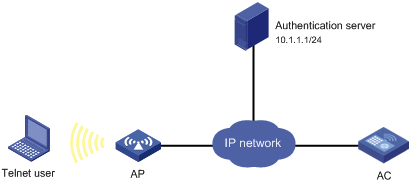
Configuration procedure
1. On the HWTACACS server, set the shared key to expert and add the Telnet user account information. (Details not shown.)
2. Configure the AC:
# Assign IP addresses to the interfaces. (Details not shown.)
# Enable the Telnet server on the AC.
<AC> system-view
[AC] telnet server enable
# Configure the AC to use AAA for Telnet users.
[AC] user-interface vty 0 4
[AC-ui-vty0-4] authentication-mode scheme
[AC-ui-vty0-4] quit
# Create an ISP domain bbb and set it as the default ISP domain.
[AC] domain bbb
[AC-isp-bbb] quit
[AC] domain default enable bbb
# Create HWTACACS scheme hwtac.
[AC] hwtacacs scheme hwtac
# Specify the primary authentication server and the service port number.
[AC-hwtacacs-hwtac] primary authentication 10.1.1.1 49
# Specify the primary authorization server and the service port number.
[AC-hwtacacs-hwtac] primary authorization 10.1.1.1 49
# Set the shared keys for authentication and authorization to expert.
[AC-hwtacacs-hwtac] key authentication simple expert
[AC-hwtacacs-hwtac] key authorization simple expert
# Configure the scheme to remove the domain name from a username before sending the username to the HWTACACS server.
[AC-hwtacacs-hwtac] user-name-format without-domain
[AC-hwtacacs-hwtac] quit
# Use either of the following methods to configure the authentication and authorization methods:
¡ Create an ISP domain and configure authentication and authorization methods for all login users in the domain.
[AC] domain bbb
[AC-isp-bbb] authentication login hwtacacs-scheme hwtac
[AC-isp-bbb] authorization login hwtacacs-scheme hwtac
[AC-isp-bbb] quit
¡ Create an ISP domain and configure the default authentication and authorization methods for all types of users in the domain.
[AC] domain bbb
[AC-isp-bbb] authentication default hwtacacs-scheme hwtac
[AC-isp-bbb] authorization default hwtacacs-scheme hwtac
Verifying the configuration
1. Telnet to the AC and enter the correct username and password.
2. Use the display connection command on the AC to display information about the user connection.
Local authentication and HWTACACS authorization for Telnet users
Network requirements
As shown in Figure 11, an HWTACACS server is located on 10.1.1.2/24 and uses the shared key expert to authenticate AAA packets.
Configure the AC to perform local authentication for Telnet users, use the HWTACACS server for Telnet user authorization, send usernames that do not include domain names to the server, and use the shared key expert to authenticate packets exchanged with the server. Add a local user on the AC and both the username and password are telnet.
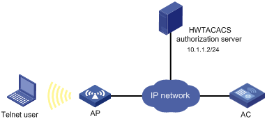
Configuration procedure
The local authentication and HWTACACS authorization configuration described in this section applies to other types of users if you correctly modify the service type in the commands.
# Assign IP addresses to the interfaces. (Details not shown.)
# Enable the Telnet server on the AC.
<AC> system-view
[AC] telnet server enable
# Configure the AC to use AAA for Telnet users.
[AC] user-interface vty 0 4
[AC-ui-vty0-4] authentication-mode scheme
[AC-ui-vty0-4] quit
# Create an ISP domain named bbb and set it as the default ISP domain.
[AC] domain bbb
[AC-isp-bbb] quit
[AC] domain default enable bbb
# Create HWTACACS scheme hwtac.
[AC] hwtacacs scheme hwtac
# Specify the primary authorization server and the service port number.
[AC-hwtacacs-hwtac] primary authorization 10.1.1.2 49
# Set the shared key for authorization to expert.
[AC-hwtacacs-hwtac] key authorization simple expert
# Configure the scheme to remove the domain name from a username before sending the username to the HWTACACS server.
[AC-hwtacacs-hwtac] user-name-format without-domain
[AC-hwtacacs-hwtac] quit
# Configure a local user with the name telnet and password telnet.
[AC] local-user telnet
[AC-luser-telnet] service-type telnet
[AC-luser-telnet] password simple telnet
# Use either of the following methods to configure the AAA methods:
· Create an ISP domain and configure authentication and authorization methods for all login users in the domain.
[AC] domain bbb
[AC-isp-system] authentication login local
[AC-isp-bbb] authorization login hwtacacs-scheme hwtac
[AC-isp-bbb] quit
· Create an ISP domain and configure the default authentication and authorization methods for all types of users.
[AC] domain bbb
[AC-isp-bbb] authentication default local
[AC-isp-bbb] authorization default hwtacacs-scheme hwtac
Verifying the configuration
1. Telnet to the AC and enter the username telnet and password telnet.
2. Use the display connection command on the AC to display information about the user connection.
LDAP authentication for Telnet users
Network requirements
As shown in Figure 12, Active Directory of the Microsoft Windows 2003 Server is an LDAP server located on 10.1.1.1/24 and the server domain name is ldap.com.
On the LDAP server, set the administrator password as admin!123456, and add a user with the username of aaa and password of ldap!123456.
Configure the AC to use the LDAP server to authenticate Telnet users.
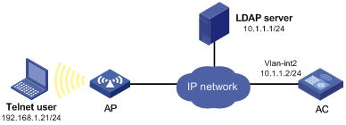
Configuration procedure
The AC does not support LDAP authorization. You can configure an HWTACACS scheme as the authorization scheme to work with LDAP authentication. For more information about HWTACACS scheme configuration, see "Configuring HWTACACS schemes."
1. Configure user aaa and the administrator password on the LDAP server:
a. Select Administrative Tools > Active Directory Users and Computers from the Start menu or launch it from the Windows Control Panel.
The Active Directory Users and Computers window appears.
b. Select Action > New > User in the top menu bar.
The New Object - User window appears.
c. Enter aaa in the First name, Full name, User logon name, and User logon name (pre-Windows 2000) fields, as shown in Figure 13, and then click Next.
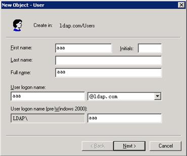
d. Enter ldap!123456 in both the Password and Confirm password fields, select the password strategy options as needed, and then click Next.
The New Object - User window closes.
Figure 14 Setting the user's password
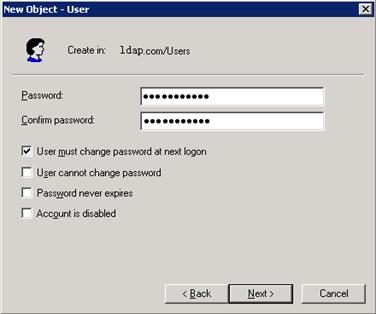
e. Click ldap.com from the navigation tree.
The list of users in the ldap.com domain appears.
f. Right-click aaa and select Properties from the shortcut menu.
The aaa Properties window appears.
g. Click the Member Of tab, and then click Add.
The Select Groups window appears.
Figure 15 Modifying user properties
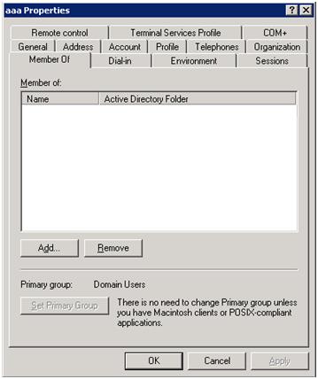
h. Enter Users in the Enter the object names to select field and click OK.
User aaa is added to the group Users.
Figure 16 Adding user aaa to group Users
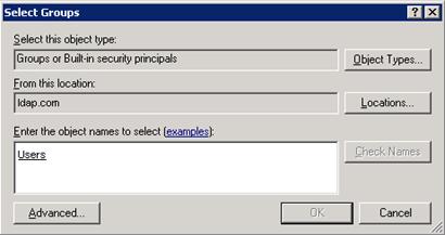
i. Right-click Administrator and select Set Password from the shortcut menu.
j. In the dialog box, set the password to admin!123456. (Details not shown.)
2. Configure the AC:
# Enable the AC to provide the Telnet service. (This step is optional because the Telnet service is enabled by default.)
<AC> system-view
[AC] telnet server enable
# Assign the IP address 10.1.1.2/24 to interface VLAN-interface 2, through which Telnet users access the AC.
[AC] vlan 2
[AC-vlan2] quit
[AC] interface vlan-interface 2
[AC-Vlan-interface2] ip address 10.1.1.2 24
[AC-Vlan-interface2] quit
# Configure the AC to use AAA for Telnet users.
[AC] user-interface vty 0 4
[AC-ui-vty0-4] authentication-mode scheme
[AC-ui-vty0-4] quit
# Create ISP domain bbb and set it as the default ISP domain.
[AC] domain bbb
[AC-isp-bbb] quit
[AC] domain default enable bbb
# Configure an LDAP scheme.
[AC] ldap scheme ldap1
# Specify the IP address of the LDAP authentication server.
[AC-ldap-ldap1] authentication-server 10.1.1.1
# Specify the administrator DN.
[AC-ldap-ldap1] login-dn cn=administrator,cn=users,dc=ldap,dc=com
# Set the administrator password.
[AC-ldap-ldap1] login-password simple admin!123456
# Configure the base DN for user search.
[AC-ldap-ldap1] user-parameters search-base-dn dc=ldap,dc=com
[AC-ldap-ldap1] quit
# Use either of the following methods to configure the authentication method:
¡ Configure the LDAP scheme to provide the authentication method for login users.
[AC] domain bbb
[AC-isp-bbb] authentication login ldap-scheme ldap1
[AC-isp-bbb] quit
¡ Configure the LDAP scheme to provide the default authentication method for all types of users.
[AC] domain bbb
[AC-isp-bbb] authentication default ldap-scheme ldap1
Verifying the configuration
# Use the username aaa and password ldap!123456 to Telnet to the AC. After authentication in the default ISP domain bbb is passed, you access the AC user interface.
AAA for portal users by a RADIUS server
Network requirements
As shown in Figure 17, the client has a public network IP address assigned manually or obtained through DHCP.
Configure the AC to provide the following functions:
· AAA for portal users through the RADIUS server.
· Direct portal authentication so that the client can access the Internet only when portal authentication is passed.
· Including the domain name in the usernames sent to the RADIUS server.
Set the shared keys for secure RADIUS communication to expert and set the ports for authentication/authorization and accounting to 1812 and 1813, respectively.
Configure a service on the RADIUS server to charge 120 dollars for up to 120 hours per month and assign the service to the portal user account.
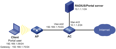
Configuration prerequisites
Configure IP addresses for the devices as shown in Figure 17 and make sure the devices can reach each other. (Details not shown.)
Select the configuration procedures based on your IMC version: 3.6 or 5.0.
Configuring the RADIUS server on IMC 3.6
This section uses IMC PLAT 3.20-R2606 and IMC UAM 3.60-E6206.
1. Add the AC to the IMC Platform as an access device:
a. Log in to IMC, click the Service tab, and select Access Service > Access Device from the navigation tree.
The Access Device page appears.
b. Click Add.
The Add Access Device page appears, as shown in Figure 18.
c. In the Access Configuration area, enter expert in the Shared Key field, 1812 in the Authentication Port field, and 1813 in the Accounting Port field, and select LAN Access Service from the Service Type list and H3C from the Access Device Type list.
d. In the Device List area, select the access device from the device list or manually add the device with the IP address 10.1.1.2.
The IP address of the access device must be the same as the source IP address of the RADIUS packets sent from the AC, which is chosen in the following order:
- IP address specified with the nas-ip command.
- IP address specified with the radius nas-ip command.
- IP address of the outbound interface (the default).
e. Click OK.
Figure 18 Adding an access device

2. Add a charging plan:
a. Click the Service tab, and select Accounting Manager > Charging Plans from the navigation tree.
The Charging Plans page appears.
b. Click Add.
The Add Charging Plan page appears, as shown in Figure 19.
c. In the Basic Information area, enter UserAcct in the Plan Name field and select Flat rate from the Charging Template list.
d. In the Basic Plan Settings area, select time from the Charge Based on list, select Monthly from the Billing Term list, and enter 120 in the Fixed Fee field.
e. In the Service Usage Limit area, enter 120 in the Usage Threshold field and select hr from the in list.
f. Click OK.
Figure 19 Adding a charging plan
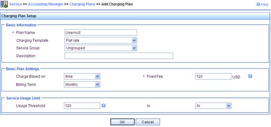
3. Add a service:
a. Click the Service tab, and select Access Service > Service Configuration from the navigation tree.
The Service Configuration page appears.
b. Click Add.
The Add Service Configuration page appears, as shown in Figure 20.
c. Enter Portal-auth/acct in the Service Name field.
d. Enter dm1 in the Service Suffix field.
Make sure the service suffix is the same as the name of the domain in which portal users are authenticated.
e. Select UserAcct from the Charging Plan list.
f. Click OK.
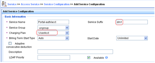
4. Add an account for portal users and assign the previous service to the account:
a. Click the User tab, and select Access User View > All Access Users from the navigation tree.
The All Access Users page appears.
b. Click Add.
The Add Access User page appears, as shown in Figure 21.
c. In the Access Information area, select or add a platform user named hello, enter portal in the Account Name field, and set the password of the user.
d. In the Access Service area, select Portal auth/acct on the Access Service list.
e. Click OK.
Figure 21 Adding an access user account
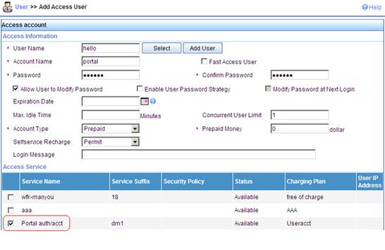
Configuring the RADIUS server on IMC 5.0
This section uses IMC PLAT 5.0 (E0101H03) and IMC UAM 5.0 SP1 (E0101P03).
1. Add the AC to the IMC Platform as an access device:
a. Log in to IMC, click the Service tab, and select User Access Manager > Access Device Management > Access Device from the navigation tree.
The Access Device page appears.
b. Click Add.
The Add Access Device page appears, as shown in Figure 22.
c. In the Access Configuration area, enter expert in the Shared Key field, 1812 in the Authentication Port field, and 1813 in the Accounting Port field, and select LAN Access Service from the Service Type list and H3C(General) from the Access Device Type list.
d. In the Device List area, select the access device from the device list or manually add the device with the IP address 10.1.1.2.
The IP address of the access device must be the same as the source IP address of the RADIUS packets sent from the AC, which is chosen in the following order:
- IP address specified with the nas-ip command.
- IP address specified with the radius nas-ip command.
- IP address of the outbound interface (the default).
e. Click OK.
Figure 22 Adding an access device
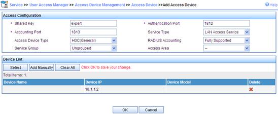
2. Add a charging plan:
a. Click the Service tab, and select Accounting Manager > Charging Plans from the navigation tree.
The Charging Plans page appears.
b. Click Add.
The Add Charging Plan page appears, as shown in Figure 23.
c. In the Basic Information area, enter UserAcct in the Plan Name field and select Flat rate from the Charging Template list.
d. In the Basic Plan Settings area, select time from the Charge Based on list, select Monthly from the Billing Term list, and enter 120 in the Fixed Fee field.
e. In the Service Usage Limit area, enter 120 in the Usage Threshold field and select hr from the in list.
f. Click OK.
Figure 23 Adding a charging plan
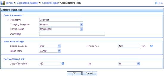
3. Add a service:
a. Click the Service tab, and select Access Service > Service Configuration from the navigation tree.
The Service Configuration page appears.
b. Click Add.
The Add Service Configuration page appears, as shown in Figure 24.
c. Enter Portal-auth/acct in the Service Name field.
d. Enter dm1 in the Service Suffix field.
Make sure the service suffix is the same as the name of the domain in which portal users are authenticated.
e. Select UserAcct from the Charging Plan list.
f. Click OK.
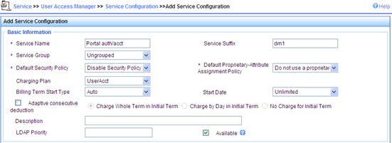
4. Add an account for portal users and assign the previous service to the account:
a. Click the User tab, and select Access User View > All Access Users from the navigation tree.
The All Access User page appears.
b. Click Add.
The Add Access User page appears, as shown in Figure 25.
c. In the Access Information area, select or add a platform user named hello, enter portal in the Account Name field, and set the password of the user.
d. In the Access Service area, select Portal auth/acct on the Access Service list.
e. Click OK.
Figure 25 Adding an access user account
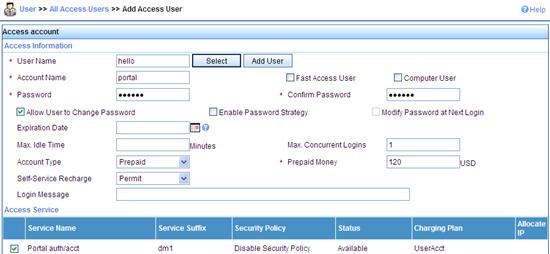
Configuring the portal server on IMC 3.6
This section uses IMC PLAT 3.20-R2606 and IMC UAM 3.60-E6206.
1. Configure the portal server:
a. Log in to IMC, click the Service tab, and select Access Service > Portal Service Management > Server from the navigation tree.
The Server page appears, as shown in Figure 26.
b. In the Portal Page field, enter the URL address of the portal authentication main page, in the format of http://ip:port/portal, where ip and port are those configured during IMC UAM installation. The default setting of port 8080 is typically used.
c. Click OK.
Figure 26 Portal server configuration
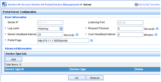
2. Configure an IP address group:
a. Select Access Service > Portal Service Management > IP Group from the navigation tree.
The Portal IP Group Configuration page appears.
b. Click Add.
The Add IP Group page appears, as shown in Figure 27.
c. Enter Portal_user in the IP Group Name field.
d. Set the start IP address to 192.168.1.1 and the end IP address to 192.168.1.255. Make sure the IP address group contains the IP address of the AC.
e. Select No from the Enable NAT list to disable NAT.
f. Click OK.
Figure 27 Adding an IP address group
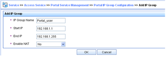
3. Configure the AC as a portal device:
a. Select Access Service > Portal Service Management > Device from the navigation tree.
The Portal Device Configuration page appears.
b. Click Add.
The Add Device page appears, as shown in Figure 28.
c. Enter NAS in the Device Name field.
d. Enter 192.168.1.70 in the Pri IP Address field, which is the IP address of the access interface on the AC.
e. Enter portal in the Key field. Make sure the key is the same as that configured on the AC.
f. Select No from the Reallocate IP list to disable IP address reallocation in this example.
g. Click OK.
Figure 28 Adding a portal device
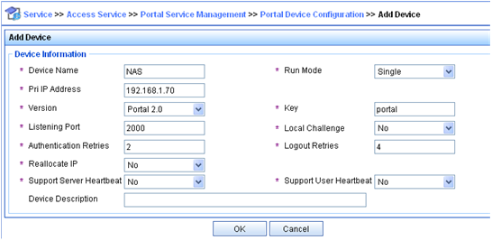
4. Associate the portal device with the IP address group:
a. On the Device Information List as shown in Figure 29, click the icon in the Port Group Information Management column for NAS.
The Port Group Info Config page appears.
b. Click Add.
The Add Port Group page appears, as shown in Figure 30.
c. Enter group in the Port Group Name field.
d. Select Portal_user from the IP Group list.
e. Click OK.
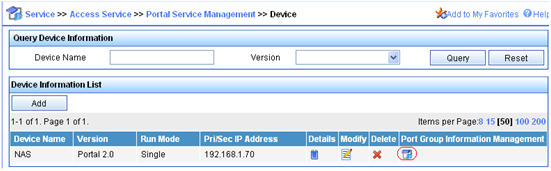
Figure 30 Associating the portal device with the IP address group
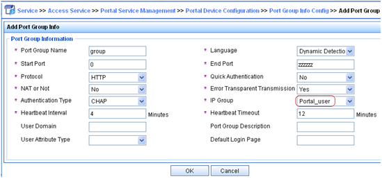
5. Select Service Parameters > Validate System Configuration from the navigation tree to validate the portal server configuration.
Configuring the portal server on IMC 5.0
This section uses IMC PLAT 5.0 (E0101H03) and IMC UAM 5.0 SP1 (E0101P03).
1. Configure the portal server:
a. Log in to IMC, click the Service tab, and select User Access Manager > Portal Service Management > Server from the navigation tree.
The Server page appears, as shown in Figure 31.
b. In the Portal Page field, enter the URL address of the portal authentication main page, in the format of http://ip:port/portal, where ip and port are those configured during IMC UAM installation. The default setting of port 8080 is typically used.
c. Click OK.
Figure 31 Portal server configuration
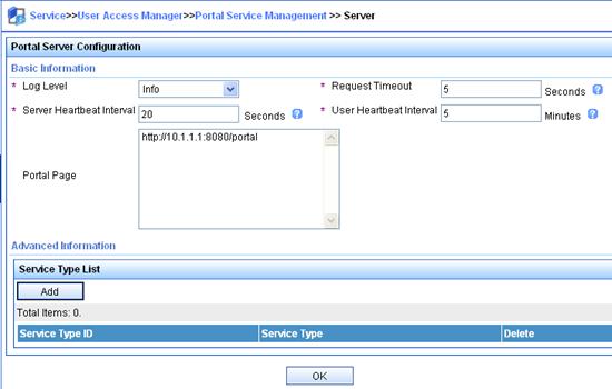
2. Configure an IP address group:
a. Select User Access Manager > Portal Service Management > IP Group from the navigation tree.
The Portal IP Group Configuration page appears.
b. Click Add.
The Add IP Group page appears, as shown in Figure 32.
c. Enter Portal_user in the IP Group Name field.
d. Set the start IP address to 192.168.1.1 and the end IP address to 192.168.1.255. Make sure the IP address group contains the IP address of the AC.
e. Select Normal from the Action list.
f. Click OK.
Figure 32 Adding an IP address group
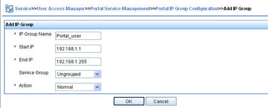
3. Configure the AC as a portal device:
a. Select User Access Manager > Portal Service Management > Device from the navigation tree.
The Portal Device Configuration page appears.
b. Click Add.
The Add Device page appears, as shown in Figure 33.
c. Enter NAS in the Device Name field.
d. Enter 192.168.1.70 in the IP Address field, which is the IP address of the access interface on the AC.
e. Enter portal in the Key field. Make sure the key is the same as that configured on the AC.
f. Select No from the Reallocate IP list to disable IP address reallocation in this example.
g. Click OK.
Figure 33 Adding a portal device
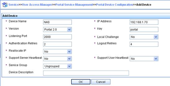
4. Associate the portal device with the IP address group:
a. On the Device Information List as shown in Figure 34, click the icon in the Port Group Information Management column for NAS.
The Port Group Info Config page appears.
b. Click Add.
The Add Port Group page appears, as shown in Figure 35.
c. Enter group in the Port Group Name field.
d. Select Portal_user from the IP Group list.
e. Click OK.
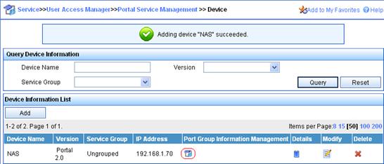
Figure 35 Associating the portal device with the IP address group
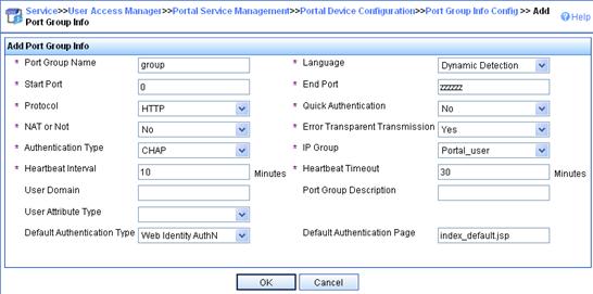
5. Select User Access Manager > Service Parameters > Validate System Configuration from the navigation tree to validate the portal server configuration.
Configuring the AC
1. Configure a RADIUS scheme:
# Create a RADIUS scheme named rs1 and enter its view.
<AC> system-view
[AC] radius scheme rs1
# Set the server type for the RADIUS scheme. When using IMC, set the server type to extended.
[AC-radius-rs1] server-type extended
# Specify the primary authentication server and primary accounting server and the service port numbers, and configure the shared keys used for communication with the servers.
[AC-radius-rs1] primary authentication 10.1.1.1 1812
[AC-radius-rs1] primary accounting 10.1.1.1 1813
[AC-radius-rs1] key authentication expert
[AC-radius-rs1] key accounting expert
# Specify the scheme to include the domain names in usernames to be sent to the RADIUS server.
[AC-radius-rs1] user-name-format with-domain
[AC-radius-rs1] quit
2. Configure an authentication domain:
# Create an ISP domain named dm1 and enter its view.
[AC] domain dm1
# Configure the ISP domain to use RADIUS scheme rs1.
[AC-isp-dm1] authentication portal radius-scheme rs1
[AC-isp-dm1] authorization portal radius-scheme rs1
[AC-isp-dm1] accounting portal radius-scheme rs1
[AC-isp-dm1] quit
3. Configure portal authentication:
# Configure the portal server.
[AC] portal server newpt ip 10.1.1.1 key portal port 50100 url http://10.1.1.1:8080/portal
[AC] portal free-rule 0 source interface Ten-GigabitEthernet1/0/1 destination any
# Enable portal authentication on the interface connecting the wireless client.
[AC] interface vlan-interface 2
[AC-Vlan-interface2] portal server newpt method direct
# Specify the portal authentication domain.
[AC–Vlan-interface2] portal domain dm1
[AC–Vlan-interface2] quit
Verifying the configuration
The user can initiate portal authentication by using the iNode client or by accessing a web page. All the initiated web requests will be redirected to the portal authentication page at http://10.1.1.1:8080/portal. Before passing portal authentication, the user can access only the authentication page. After passing portal authentication, the user can access the Internet.
After the user passes portal authentication, display the portal user information on the AC.
[AC] display portal user interface vlan-interface 2
Index:19
State:ONLINE
SubState:NONE
ACL:NONE
Work-mode:stand-alone
MAC IP Vlan Interface
---------------------------------------------------------------------
0015-e9a6-7cfe 192.168.1.58 2 Vlan-interface2
Total 1 user(s) matched, 1 listed.
# Use the display connection command to view the connection information on the AC.
[AC] display connection
Index=20 ,Username=portal@dm1
MAC=00-15-E9-A6-7C-FE
IP=192.168.1.58
IPv6=N/A
Online=03h01m37s
Total 1 connection(s) matched.
AAA for 802.1X users by a RADIUS server
Network requirements
As shown in Figure 36, configure the AC to provide the following functions:
· Implementing AAA for the 802.1X user on the client through the RADIUS server.
· Using the WLAN-ESS port as the authentication port.
· Including the domain name in the username sent to the RADIUS server. The username is dot1x@bbb.
Set the shared keys for secure RADIUS communication to expert and set the ports for authentication/authorization and accounting to 1812 and 1813, respectively.
Configure the RADIUS server to assign the client to VLAN 4 when authentication is passed.
Configure a service on the RADIUS server to charge 120 dollars for up to 120 hours per month and assign the service to the 802.1X user account.
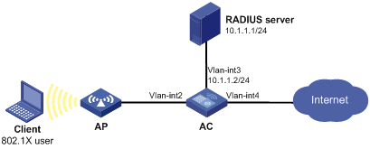
Configuration prerequisites
Configure the interfaces and VLANs as shown in Figure 36. Make sure the client can get a new IP address manually or automatically and can access resources in the authorized VLAN after passing authentication.
Select the configuration procedures based on your IMC version: 3.6 or 5.0.
Configuring the RADIUS server on IMC 3.6
This section uses IMC PLAT 3.20-R2606 and IMC UAM 3.60-E6206.
1. Add the AC to the IMC Platform as an access device:
a. Log in to IMC, click the Service tab, and select Access Service > Access Device from the navigation tree.
The Access Device page appears.
b. Click Add.
The Add Access Device page appears, as shown in Figure 37.
c. In the Access Configuration area, enter expert in the Shared Key field, 1812 in the Authentication Port field, and 1813 in the Accounting Port field, and select LAN Access Service from the Service Type list and H3C from the Access Device Type list.
d. In the Device List area, select the access device from the device list or manually add the device with the IP address 10.1.1.2.
The IP address of the access device must be the same as the source IP address of the RADIUS packets sent from the AC, which is chosen in the following order:
- IP address specified with the nas-ip command.
- IP address specified with the radius nas-ip command.
- IP address of the outbound interface (the default).
e. Click OK.
Figure 37 Adding an access device
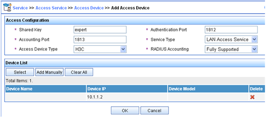
2. Add a charging plan:
a. Click the Service tab, and select Accounting Manager > Charging Plans from the navigation tree.
The Charging Plans page appears.
b. Click Add.
The Add Charging Plan page appears, as shown in Figure 38.
c. In the Basic Information area, enter UserAcct in the Plan Name field and select Flat rate from the Charging Template list.
d. In the Basic Plan Settings area, select time from the Charge Based on list, select Monthly from the Billing Term list, and enter 120 in the Fixed Fee field.
e. In the Service Usage Limit area, enter 120 in the Usage Threshold field and select hr from the in list.
f. Click OK.
Figure 38 Adding a charging plan
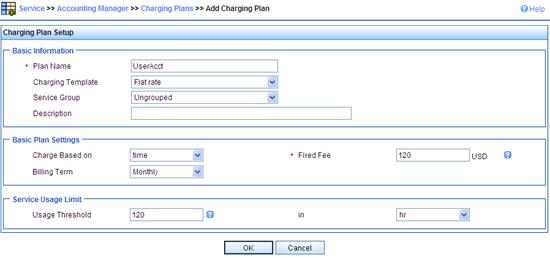
3. Add a service:
a. Click the Service tab, and select Access Service > Service Configuration from the navigation tree.
The Service Configuration page appears.
b. Click Add.
The Add Service Configuration page appears, as shown in Figure 39.
c. Enter Dot1x auth in the Service Name field.
d. Enter bbb in the Service Suffix field.
Make sure the service suffix is the same as the name of the domain in which the 802.1X user is authenticated.
e. Select UserAcct from the Charging Plan list.
f. If certificate authentication is required, configure parameters in the Authorization Information area. Click EAP next to the Certificate Authentication field, select EAP-PEAP AuthN from the Certificate Type list, select MS-CHAPv2 AuthN from the Certificate Sub-Type list, select the Deploy VLAN option, and enter 4 in the box.
g. Click OK.
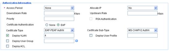
4. Add an account for 802.1X users and assign the previous service to the account:
a. Click the User tab, and select Access User View > All Access Users from the navigation tree.
The All Access Users page appears.
b. Click Add.
The Add Access User page appears, as shown in Figure 40.
c. In the Access Information area, select or add a platform user named test, enter dot1x in the Account Name field, and set the password of the user.
d. In the Access Service area, select Dot1x auth on the Access Service list.
e. Click OK.
Figure 40 Adding an access user account
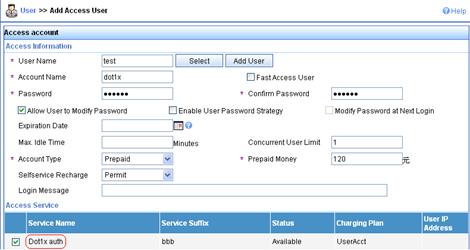
Configuring the RADIUS server on IMC 5.0
This section uses IMC PLAT 5.0 (E0101H03) and IMC UAM 5.0 SP1 (E0101P03).
1. Add the AC to the IMC Platform as an access device:
a. Log in to IMC, click the Service tab, and select User Access Manager > Access Device Management > Access Device from the navigation tree.
The Access Device page appears.
b. Click Add.
The Add Access Device page appears, as shown in Figure 41.
c. In the Access Configuration area, enter expert in the Shared Key field, 1812 in the Authentication Port field, and 1813 in the Accounting Port field, and select LAN Access Service from the Service Type list and H3C(General) from the Access Device Type list.
d. In the Device List area, select the access device from the device list or manually add the device with the IP address 10.1.1.2.
The IP address of the access device must be the same as the source IP address of the RADIUS packets sent from the AC, which is chosen in the following order:
- IP address specified with the nas-ip command.
- IP address specified with the radius nas-ip command.
- IP address of the outbound interface (the default).
e. Click OK.
Figure 41 Adding an access device
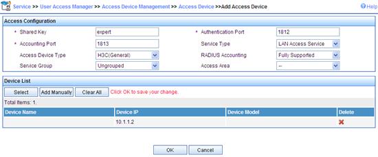
2. Add a charging plan:
a. Click the Service tab, and select Accounting Manager > Charging Plans from the navigation tree.
The Charging Plans page appears.
b. Click Add.
The Add Charging Plan page appears, as shown in Figure 42.
c. In the Basic Information area, enter UserAcct in the Plan Name field and select Flat rate from the Charging Template list.
d. In the Basic Plan Settings area, select time from the Charge Based on list, select Monthly from the Billing Term list, and enter 120 in the Fixed Fee field.
e. In the Service Usage Limit area, enter 120 in the Usage Threshold field and select hr from the in list.
f. Click OK.
Figure 42 Adding a charging plan

3. Add a service:
a. Click the Service tab, and select User Access Manager > Service Configuration from the navigation tree.
The Service Configuration page appears.
b. Click Add.
The Add Service Configuration page appears, as shown in Figure 43.
c. Enter Dot1x auth in the Service Name field.
d. Enter bbb in the Service Suffix field.
Make sure the service suffix is the same as the name of the domain in which the 802.1X user is authenticated.
e. Select UserAcct from the Charging Plan list.
f. If certificate authentication is required, configure parameters in the Authorization Information area. Click EAP next to the Certificate Authentication field, select EAP-PEAP AuthN from the Certificate Type list, select MS-CHAPv2 AuthN from the Certificate Sub-Type list, select the Deploy VLAN option, and enter 4 in the box.
g. Click OK.
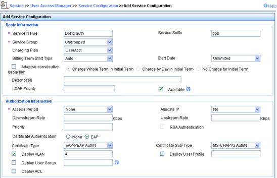
4. Add an account for portal users and assign the previous service to the account:
a. Click the User tab, and select Access User View > All Access Users from the navigation tree.
The All Access User page appears.
b. Click Add.
The Add Access User page appears, as shown in Figure 44.
c. In the Access Information area, select or add a platform user named hello, enter dot1x in the Account Name field, and set the password of the user.
d. In the Access Service area, select Dot1x auth on the Access Service list.
e. Click OK.
Figure 44 Adding an access user account
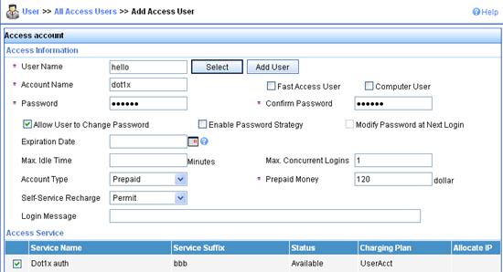
Configuring the AC
1. Configure a RADIUS scheme:
# Create a RADIUS scheme named rad and enter its view.
<AC> system-view
[AC] radius scheme rad
# Set the server type for the RADIUS scheme. When using IMC, set the server type to extended.
[AC-radius-rad] server-type extended
# Specify the primary authentication server and primary accounting server and the service port numbers, and configure the keys used for communication with the servers.
[AC-radius-rad] primary authentication 10.1.1.1 1812
[AC-radius-rad] primary accounting 10.1.1.1 1813
[AC-radius-rad] key authentication simple expert
[AC-radius-rad] key accounting simple expert
# Specify the scheme to include the domain names in usernames to be sent to the RADIUS server.
[AC-radius-rad] user-name-format with-domain
[AC-radius-rad] quit
2. Configure an authentication domain:
# Create an ISP domain named bbb and enter its view.
[AC] domain bbb
# Configure the ISP domain to use RADIUS scheme rad.
[AC-isp-bbb] authentication lan-access radius-scheme rad
[AC-isp-bbb] authorization lan-access radius-scheme rad
[AC-isp-bbb] accounting lan-access radius-scheme rad
[AC-isp-bbb] quit
3. Configure 802.1X authentication:
# Enable port security globally.
[AC] port-security enable
# Specify the 802.1X authentication method.
[AC] dot1x authentication-method eap
# Create a WLAN-ESS interface and configure the port security mode as userLoginSecureExt.
[AC] interface wlan-ess 1
[AC-WLAN-ESS1] port-security port-mode userlogin-secure-ext
# Enable the key negotiation function for the port.
[AC-WLAN-ESS1] port-security tx-key-type 11key
# Disable the online user handshake function.
[AC-WLAN-ESS1] undo dot1x handshake
# Disable the 802.1X multicast trigger function.
[AC-WLAN-ESS1] undo dot1x multicast-trigger
# Configure the port to use mandatory authentication domain bbb. Then, the AC will use the authentication, authorization, and accounting methods of this domain for all users accessing this port. This step is optional.
[AC-WLAN-ESS1] dot1x mandatory-domain bbb
[AC-WLAN-ESS1] quit
# Configure the WLAN service template.
[AC] wlan service-template 1 crypto
[AC-wlan-st-1] ssid sectest
[AC-wlan-st-1] bind WLAN-ESS 1
[AC-wlan-st-1] authentication-method open-system
[AC-wlan-st-1] cipher-suite tkip
[AC-wlan-st-1] security-ie wpa
[AC-wlan-st-1] service-template enable
[AC-wlan-st-1] quit
# Create an AP template named ap1, and specify its model as WA3628i-AGN and serial number as 210235A29G007C000020.
[AC] wlan ap ap1 model WA3628i-AGN
[AC-wlan-ap-ap1] serial-id 210235A29G007C000020
# Bind service template 1 to radio 1.
[AC-wlan-ap-ap1] radio 1 type dot11an
[AC-wlan-ap-ap1-radio-1] service-template 1
[AC-wlan-ap-ap1-radio-1] radio enable
[AC-wlan-ap-ap1-radio-1] quit
[AC-wlan-ap-ap1] quit
Verifying the configuration
To use the 802.1X client of Windows XP, follow these steps:
1. Click the Authentication tab on the Properties dialog box of 802.1X connection, select the Enable IEEE 802.1X authentication for this network option and select Protected EAP (PEAP) from the EAP Type list.
2. Enter the correct username and password in the authentication page.
To use the iNode client, enter username dot1x@bbb and the correct password in the client property window.
After the user passes authentication, the server assigns the port connecting the client to VLAN 4.
# Use the display connect command to view the connection information on the AC.
[AC] display connection
Index=22 , Username=dot1x@bbb
MAC=0015-e9a6-7cfe
IP=192.168.1.58
IPv6=N/A
Online=00h01m37s
Total 1 connection(s) matched.
# View the information of the specified connection on the AC.
[AC] display connection ucibindex 22
Index=22 , Username=dot1x@bbb
MAC=0015-e9a6-7cfe
IP=192.168.1.58
IPv6=N/A
Access=8021X ,AuthMethod=EAP
Port Type=Wireless-802.11,Port Name=WLAN-DBSS1:1
Initial VLAN=2, Authorized VLAN=4
ACL Group=Disable
User Profile=N/A
CAR=Disable
Traffic Statistic:
InputOctets =12121212 OutputOctets =12120
InputGigawords=1 OutputGigawords=0
Priority=Disable
SessionTimeout=86236(s), Terminate-Action=Default
Start=2013-05-26 19:41:12 ,Current=2013-05-26 19:42:55 ,Online=00h01m43s
Total 1 connection matched.
The Authorized VLAN field in the output shows VLAN 4 has been assigned to the user.
Local EAP authentication and authorization for 802.1X users
Network requirements
As shown in Figure 45, configure the AC to perform local EAP authentication and authorization for 802.1X users.
· Use the EAP-MD5 authentication method for the 802.1X user.
· Add the 802.1X user to user group dot1x.
· Configure the authorized VLAN of VLAN 100 for the user group.
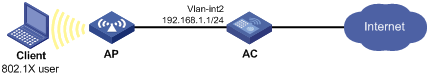
Configuration procedure
1. Configure the 802.1X connection properties if the 802.1X client of Windows XP is used:
a. Open the Properties dialog box of the 802.1X connection.
b. On the Authentication tab, select the Enable IEEE 802.1X authentication for this network option and select MD5-Challenge from the EAP Type list.
c. Click OK.
2. Configure the AC:
# Create user group dot1x, configure the authorized VLAN as VLAN 100.
<AC> system-view
[AC] user-group dot1x
[AC-ugroup-dot1x] authorization-attribute vlan 100
[AC-ugroup-dot1x] quit
# Create local user usera, and add the user to user group dot1x.
[AC] local-user usera
[AC-luser-usera] group dot1x
[AC-luser-usera] password simple 1234
[AC-luser-usera] service-type lan-access
[AC-luser-usera] quit
# Configure the ISP domain to use local authentication and authorization.
[AC] domain mydomain
[AC-isp-mydomain] authentication lan-access local
[AC-isp-mydomain] authorization lan-access local
[AC-isp-mydomain] quit
# Configure an EAP profile, specifying to use EAP-MD5 for authentication.
[AC] eap-profile eapsvr
[AC-eap-prof-eapsvr] method md5
[AC-eap-prof-eapsvr] quit
# Configure the local EAP authentication server, specifying to use EAP profile eapsvr.
[AC] local-server authentication eap-profile eapsvr
# Enable port security globally.
[AC] port-security enable
# Specify the 802.1X authentication method.
[AC] dot1x authentication-method eap
# Create a WLAN interface and configure the port security mode as userLoginSecureExt.
[AC] interface wlan-ess 1
[AC-WLAN-ESS1] port-security port-mode userlogin-secure-ext
# Enable the key negotiation function for the port.
[AC-WLAN-ESS1] port-security tx-key-type 11key
# Disable the online user handshake function.
[AC-WLAN-ESS1] undo dot1x handshake
# Disable the 802.1X multicast trigger function.
[AC-WLAN-ESS1] undo dot1x multicast-trigger
# Configure the port to use mandatory authentication domain mydomain. Then, the AC will use the authentication, authorization, and accounting methods of this domain for all users accessing this port. This step is optional.
[AC-WLAN-ESS1] dot1x mandatory-domain mydomain
[AC-WLAN-ESS1] quit
# Create a WLAN service template.
[AC] wlan service-template 1 crypto
[AC-wlan-st-1] ssid sectest
[AC-wlan-st-1] bind WLAN-ESS 1
[AC-wlan-st-1] authentication-method open-system
[AC-wlan-st-1] cipher-suite tkip
[AC-wlan-st-1] security-ie wpa
[AC-wlan-st-1] service-template enable
[AC-wlan-st-1] quit
# Create an AP template named ap1, and specify its model as WA3628i-AGN and serial number as 210235A29G007C000020.
[AC] wlan ap ap1 model WA3628i-AGN
[AC-wlan-ap-ap1] serial-id 210235A29G007C000020
# Bind service template 1 to radio 1.
[AC-wlan-ap-ap1] radio 1 type dot11an
[AC-wlan-ap-ap1-radio-1] service-template 1
[AC-wlan-ap-ap1-radio-1] radio enable
[AC-wlan-ap-ap1-radio-1] quit
[AC-wlan-ap-ap1] quit
Verifying the configuration
1. Trigger EAP authentication and enter the 802.1X username usera@mydomain and password 1234.
2. Use the display connection command on the AC to view the user's connection information.
3. Use the display interface wlan-dbss command to check that the WLAN-DBSS access port belongs to VLAN 100.
RADIUS offload for 802.1X users
Network requirements
As shown in Figure 46, configure the AC to work with the RADIUS server for RADIUS authentication, authorization, and accounting of 802.1X users.
· The RADIUS server does not support EAP authentication.
· Configure PEAP-MSCHAPv2 authentication between the 802.1X client and the AC.
· Configure the AC and the RADIUS server to use the shared key expert to secure RADIUS authentication and accounting.
Configuration prerequisites
· To use the 802.1X client of Windows XP, configure the 802.1X connection properties as follows:
a. Open the Properties dialog box of the 802.1X connection.
b. On the Authentication tab, select the Enable IEEE 802.1X authentication for this network option and select Protected EAP (PEAP) from the EAP Type list.
c. Click Properties, and in the popup dialog box, select Secured password (EAP-MSCHAP v2) from the Select Authentication Method list and click OK.
d. Click OK.
· To use the iNode client, configure the 802.1X connection properties as follows:
a. Open the Properties dialog box of the 802.1X connection in the iNode client.
b. On the General tab, select the Enable advanced authentication option and select the Certificate authentication option.
c. Click OK.
· On the RADIUS server, configure the shared key for authenticating packets exchanged with the AC to expert, and add a username and password for the 802.1X user. (Details not shown.)
Configuration procedure
1. Obtain the CA certificate and local certificate.
If the CA certificate file and local certificate file are already saved on the AC, import the certificates in offline mode. Otherwise, you must request a local certificate for the AC and obtain the CA certificate in online mode. Suppose that the PKI domain is eappki. For more information about the configuration steps, see "Configuring PKI."
2. Create SSL server policy eapsvr and configure it to use PKI domain eappki.
<AC> system-view
[AC] ssl server-policy eapsvr
[AC-ssl-server-policy-eapsvr] pki-domain eappki
[AC-ssl-server-policy-eapsvr] quit
3. Configure the local EAP authentication server:
# Create an EAP profile.
[AC] eap-profile eapsvr
# Configure the EAP profile to use PEAP-MSCHAPv2 authentication.
[AC-eap-prof-eapsvr] method peap-mschapv2
# Configure the EAP profile to use SSL server policy eapsvr for EAP authentication.
[AC-eap-prof-eapsvr] ssl-server-policy eapsvr
[AC-eap-prof-eapsvr] quit
# Configure the local EAP authentication server, specifying to use EAP profile eapsvr.
[AC] local-server authentication eap-profile eapsvr
4. Configure AAA:
# Configure a RADIUS scheme that supports the EAP offload function.
[AC] radius scheme radoff
[AC-radius-radoff] primary authentication 10.1.1.1
[AC-radius-radoff] primary accounting 10.1.1.1
[AC-radius-radoff] key authentication simple expert
[AC-radius-radoff] key accounting simple expert
[AC-radius-radoff] eap offload method peap-mschapv2
[AC-radius-radoff] quit
# Configure the AAA method for the ISP domain.
[AC] domain bbb
[AC-isp-bbb] authentication lan-access radius-scheme radoff
[AC-isp-bbb] authorization lan-access radius-scheme radoff
[AC-isp-bbb] accounting lan-access radius-scheme radoff
[AC-isp-bbb] quit
5. Configure 802.1X:
# Enable port security globally.
[AC] port-security enable
# Specify the 802.1X authentication method.
[AC] dot1x authentication-method eap
# Create a WLAN interface and configure the port security mode as userLoginSecureExt.
[AC] interface wlan-ess 1
[AC-WLAN-ESS1] port-security port-mode userlogin-secure-ext
# Enable the key negotiation function for the port.
[AC-WLAN-ESS1] port-security tx-key-type 11key
# Disable the online user handshake function.
[AC-WLAN-ESS1] undo dot1x handshake
# Disable the 802.1X multicast trigger function.
[AC-WLAN-ESS1] undo dot1x multicast-trigger
# Configure the port to use mandatory authentication domain bbb. Then, the AC will use the authentication, authorization, and accounting methods of this domain for all users accessing this port. This step is optional.
[AC-WLAN-ESS1] dot1x mandatory-domain bbb
[AC-WLAN-ESS1] quit
# Configure the WLAN service template.
[AC] wlan service-template 1 crypto
[AC-wlan-st-1] ssid sectest
[AC-wlan-st-1] bind WLAN-ESS 1
[AC-wlan-st-1] authentication-method open-system
[AC-wlan-st-1] cipher-suite tkip
[AC-wlan-st-1] security-ie wpa
[AC-wlan-st-1] service-template enable
[AC-wlan-st-1] quit
# Create an AP template named ap1, and specify its model as WA3628i-AGN and serial number as 210235A29G007C000020.
[AC] wlan ap ap1 model WA3628i-AGN
[AC-wlan-ap-ap1] serial-id 210235A29G007C000020
# Bind service template 1 to radio 1.
[AC-wlan-ap-ap1] radio 1 type dot11an
[AC-wlan-ap-ap1-radio-1] service-template 1
[AC-wlan-ap-ap1-radio-1] radio enable
[AC-wlan-ap-ap1-radio-1] quit
[AC-wlan-ap-ap1] quit
Verifying the configuration
1. Use the display radius scheme radoff and display domain bbb commands to view AAA configuration.
2. Use the display dot1x interface wlan-ess1 command to view 802.1X configuration.
3. After the 802.1X user passes EAP authentication by using the username in the username@bbb format and successfully logs in, use the display connection command to display the user's connection information.
Level switching authentication for Telnet users by an HWTACACS server
Network requirements
As shown in Figure 47, the Telnet user communicates with the AC through the AP and the AC connects to the HWTACACS server. Configure the AC to use the HWTACACS server for level switching authentication of the Telnet user:
· Configure an ACS server to act as an HWTACACS server for Telnet user authentication. The IP address of the server is 10.1.1.1/24.
· Set the shared key for authenticating authentication packets to expert and specify that usernames sent to the HWTACACS server do not include domain names.
· Configure the AC to use local authentication for the Telnet user and assign the privilege level of 0 for the user after login.
· Configure the AC to use the HWTACACS server and, if HWTACACS authentication is not available, use local authentication for level switching authenticate of the Telnet user.
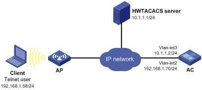
Configuration procedure
1. Configure the HWTACACS server.
In this example, the HWTACACS server runs ACSv4.0.
Add a user named test on the HWTACACS server, and configure advanced attributes for the user as follows:
a. Select Max Privilege for any AAA Client and set the privilege level to level 3. This setting requires the user to enter the password when switching to level 1, level 2, or level 3.
b. Select Use separate password and specify the password as enabpass.
Figure 48 Configuring advanced attributes for the Telnet user
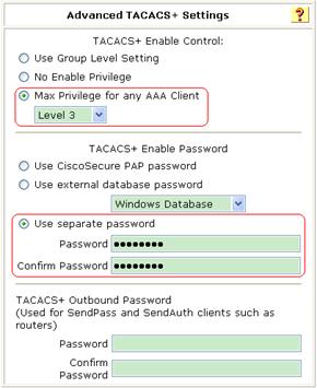
2. Configure the AC:
# Assign an IP address to VLAN-interface 2, the interface used to connect the client.
<AC> system-view
[AC] interface vlan-interface 2
[AC-Vlan-interface2] ip address 192.168.1.70 255.255.255.0
[AC-Vlan-interface2] quit
# Assign an IP address to VLAN-interface 3, the interface used to connect the server.
[AC] interface vlan-interface 3
[AC-Vlan-interface3] ip address 10.1.1.2 255.255.255.0
[AC-Vlan-interface3] quit
# Enable the AC to provide Telnet services.
[AC] telnet server enable
# Configure the AC to use AAA for Telnet users.
[AC] user-interface vty 0 4
[AC-ui-vty0-4] authentication-mode scheme
[AC-ui-vty0-4] quit
# Create an ISP domain bbb and set it as the default ISP domain.
[AC] domain bbb
[AC-isp-bbb] quit
[AC] domain default enable bbb
# Create an HWTACACS scheme named hwtac.
[AC] hwtacacs scheme hwtac
# Specify the IP address of the primary authentication server as 10.1.1.1 and the port for authentication as 49.
[AC-hwtacacs-hwtac] primary authentication 10.1.1.1 49
# Set the shared key for authenticating authentication packets to expert.
[AC-hwtacacs-hwtac] key authentication simple expert
# Specify that usernames sent to the HWTACACS server do not include domain names.
[AC-hwtacacs-hwtac] user-name-format without-domain
[AC-hwtacacs-hwtac] quit
# Configure ISP domain bbb to use local authentication for Telnet users.
[AC] domain bbb
[AC-isp-bbb] authentication login local
# Configure to use HWTACACS scheme hwtac for privilege level switching authentication.
[AC-isp-bbb] authentication super hwtacacs-scheme hwtac
[AC-isp-bbb] quit
# Create a local Telnet user account test.
[AC] local-user test
[AC-luser-test] service-type telnet
[AC-luser-test] password simple aabbcc
# Configure the user level of the Telnet user as 0 after user login.
[AC-luser-test] authorization-attribute level 0
[AC-luser-test] quit
# Configure the AC to use the HWTACACS server for level switching authentication, and to use local authentication as the backup method.
[AC] super authentication-mode scheme local
# Configure the password for privilege level switching authentication as 654321.
[AC] super password simple 654321
[AC] quit
Verifying the configuration
1. Telnet to the AC from the client, and enter the username test and password aabbcc. After login, you can access level 0 commands.
2. Perform user privilege level switching:
# Execute the command for switching to user privilege level 3 and enter password pass3 as prompted.
<AC> super 3
Password:
User privilege level is 3, and only those commands can be used
whose level is equal or less than this.
Privilege note: 0-VISIT, 1-MONITOR, 2-SYSTEM, 3-MANAGE
# If the ACS server is not reachable, enter password 654321 as prompted for local authentication.
<AC> super 3
Password: ß Enter the password for HWTACACS level switching authentication
Error: Invalid configuration or no response from the authentication server.
Info: Change authentication mode to local.
Password: ß Enter the password for local level switching authentication
User privilege level is 3, and only those commands can be used
whose level is equal or less than this.
Privilege note: 0-VISIT, 1-MONITOR, 2-SYSTEM, 3-MANAGE
Local EAP authentication for 802.1X users by an LDAP server
Network requirements
As shown in Figure 49, an 802.1X client connects to an AC that connects to an LDAP server. The IP address of the LDAP server is 10.1.1.1/24 and the domain name is ldap.com. Configure the AC to perform local EAP authentication for 802.1X users and to use the LDAP server for user identity authentication.
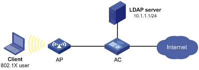
Configuration prerequisites
· Configure the 802.1X connection properties if the 802.1X client of Windows XP is used:
a. Open the Properties dialog box of the 802.1X connection.
b. On the Authentication tab, select the Enable IEEE 802.1X authentication for this network option and select the smart card or other certificates as the EAP authentication type.
· To use the iNode client, configure the 802.1X connection properties as follows:
a. Open the Properties dialog box of the 802.1X connection in the iNode client.
b. On the General tab, select the Enable advanced authentication option and select the Certificate authentication option.
c. Click Settings, and in the popup dialog box, select the EAP-TLS in the Authentication Type area and click OK.
d. Click OK.
Configuration procedure
1. Configure the LDAP server.
Set the administrator's password to admin!123456, add user aaa (this username is the DN of the local certificate) and set the password for the user to ldap!123456. For more information about LDAP server configuration, see "LDAP authentication for Telnet users."
2. Configure the AC:
# Obtain the CA certificate and the local certificate.
If the AC has saved the CA certificate file and local certificate file, import them in offline mode. Otherwise, you must request a local certificate for the AC and obtain the CA certificate in online mode. Suppose that the PKI domain is eappki. For more information about the configuration steps, see "Configuring PKI."
# Specify an LDAP scheme.
<AC> system-view
[AC] ldap scheme ldap1
# Specify the IP address of the LDAP authentication server.
[AC-ldap-ldap1] authentication-server 10.1.1.1
# Specify the administrator DN.
[AC-ldap-ldap1] login-dn cn=administrator,cn=users,dc=ldap,dc=com
# Specify the administrator password.
[AC-ldap-ldap1] login-password simple admin!123456
# Configure the base directory for user search.
[AC-ldap-ldap1] user-parameters search-base-dn dc=ldap,dc=com
[AC-ldap-ldap1] quit
# Specify the domain to use local authentication/authorization. (Authorization for 802.1X users by an LDAP server is not supported. Local authorization is used here)
[AC] domain bbb
[AC-isp-bbb] authentication lan-access local
[AC-isp-bbb] authorization lan-access local
[AC-isp-bbb] quit
# Configure the SSL server policy sp1, specifying the PKI domain to be used as eappki.
[AC] ssl server-policy sp1
[AC-ssl-server-policy-sp1] pki-domain eappki
[AC-ssl-server-policy-sp1] quit
# Create an EAP profile and configure it to use EAP-TLS for authentication.
[AC] eap-profile eapsvr
[AC-eap-prof-eapsvr] method tls
# Specify the SSL server policy for EAP authentication as sp1.
[AC-eap-prof-eapsvr] ssl-server-policy sp1
# Use the LDAP database for user credential verification and reference the LDAP scheme ldap1.
[AC-eap-prof-eapsvr] user-credentials ldap-scheme ldap1
[AC-eap-prof-eapsvr] quit
# Configure the local EAP authentication server, specifying to use EAP profile eapsvr.
[AC] local-server authentication eap-profile eapsvr
# Enable port security globally.
[AC] port-security enable
# Specify the 802.1X authentication method.
[AC] dot1x authentication-method eap
# Create a WLAN interface and configure the port security mode as userLoginSecureExt.
[AC] interface wlan-ess 1
[AC-WLAN-ESS1] port-security port-mode userlogin-secure-ext
# Enable the key negotiation function for the port.
[AC-WLAN-ESS1] port-security tx-key-type 11key
# Disable the online user handshake function.
[AC-WLAN-ESS1] undo dot1x handshake
# Disable the 802.1X multicast trigger function.
[AC-WLAN-ESS1] undo dot1x multicast-trigger
# Configure the port to use mandatory authentication domain bbb. Then, the AC will use the authentication, authorization, and accounting methods of this domain for all users accessing this port. This step is optional.
[AC-WLAN-ESS1] dot1x mandatory-domain bbb
[AC-WLAN-ESS1] quit
# Configure the WLAN service template.
[AC] wlan service-template 1 crypto
[AC-wlan-st-1] ssid sectest
[AC-wlan-st-1] bind WLAN-ESS 1
[AC-wlan-st-1] authentication-method open-system
[AC-wlan-st-1] cipher-suite tkip
[AC-wlan-st-1] security-ie wpa
[AC-wlan-st-1] service-template enable
[AC-wlan-st-1] quit
# Create an AP template named ap1, and specify its model as WA3628i-AGN and serial number as 210235A29G007C000020.
[AC] wlan ap ap1 model WA3628i-AGN
[AC-wlan-ap-ap1] serial-id 210235A29G007C000020
# Bind service template 1 to radio 1.
[AC-wlan-ap-ap1] radio 1 type dot11an
[AC-wlan-ap-ap1-radio-1] service-template 1
[AC-wlan-ap-ap1-radio-1] radio enable
[AC-wlan-ap-ap1-radio-1] quit
[AC-wlan-ap-ap1] quit
Verifying the configuration
1. Use the display dot1x interface wlan-ess 1 command to check the configuration.
2. After the 802.1X user passes certificate-based EAP authentication, check the user's connectivity status by using the display connection command.
Temporary access control of wireless users
Network requirements
Wireless users temporarily access the network through an AP whose ID is 210235A29G007C000020. The AC uses local EAP authentication (EAP-TLS) for user authentication.
Configure a guest account on the AC for the wireless users and configure the following restrictions for the guest account:
· The expiration time of the guest account is 12:00:00 on August 8, 2011.
· Only users with the SSID aabbcc can use the guest account for login.
Figure 50 Network diagram
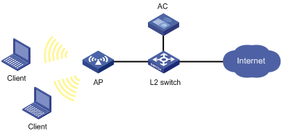
Configuration prerequisites
· Configure the 802.1X connection properties if the 802.1X client of Windows XP is used:
a. Open the Properties dialog box of the 802.1X connection.
b. On the Authentication tab, select the Enable IEEE 802.1X authentication for this network option and select the smart card or other certificates as the EAP authentication type.
· To use the iNode client, configure the 802.1X connection properties as follows:
a. Open the Properties dialog box of the 802.1X connection in the iNode client.
b. On the General tab, select the Enable advanced authentication option and select the Certificate authentication option.
c. Click Settings, and in the popup dialog box, select the EAP-TLS in the Authentication Type area and click OK.
d. Click OK.
Configuration procedure
1. Obtain the CA certificate and the local certificate.
If the AC has a copy of the CA certificate file and local certificate file, import the certificates in offline mode. Otherwise, request a certificate for the AC and obtain the CA certificate in online mode. The PKI domain for the certificate is eappki. (Details not shown. For information about PKI configuration, see "Configuring PKI.")
2. Create the SSL server side policy eapsvr and specify the PKI domain as eappki.
<AC> system-view
[AC] ssl server-policy eapsvr
[AC-ssl-server-policy-eapsvr] pki-domain eappki
[AC-ssl-server-policy-eapsvr] quit
3. Configure port security:
# Enable port security globally.
[AC] port-security enable
# Set the 802.1X authentication method to EAP.
[AC] dot1x authentication-method eap
# Create a WLAN interface and configure the port security mode.
[AC] interface wlan-ess 1
[AC-WLAN-ESS1] port-security port-mode userlogin-secure-ext
# Disable the multicast trigger function.
[AC-WLAN-ESS1] undo dot1x multicast-trigger
# Disable the online user handshake function.
[AC-WLAN-ESS1] undo dot1x handshake
# Configure the port to use mandatory authentication domain test. With this configuration, the AC will use the authentication, authorization, and accounting methods of this domain for all 802.1X users accessing the port. This configuration is optional.
[AC-WLAN-ESS1] dot1x mandatory-domain test
[AC-WLAN-ESS1] quit
4. Configure AAA methods:
# Create an ISP domain and configure the domain to use local authentication and authorization methods.
[AC] domain test
[AC-isp-test] authentication lan-access local
[AC-isp-test] authorization lan-access local
[AC-isp-test] quit
# Configure domain test as the default domain.
[AC] domain default enable test
5. Configure the local EAP authentication server
# Create an EAP profile and configure it to use EAP-TLS for authentication.
[AC] eap-profile eapsvr
[AC-eap-prof-eapsvr] method tls
# Specify the SSL server side policy for EAP authentication as eapsvr.
[AC-eap-prof-eapsvr] ssl-server-policy eapsvr
[AC-eap-prof-eapsvr] quit
# Configure the local EAP authentication server, specifying to use EAP profile eapsvr.
[AC] local-server authentication eap-profile eapsvr
6. Configure WLAN service:
# Configure the service template.
[AC] wlan service-template 1 clear
[AC-wlan-st-1] ssid aabbcc
[AC-wlan-st-1] bind WLAN-ESS 1
[AC-wlan-st-1] authentication-method open-system
[AC-wlan-st-1] service-template enable
[AC-wlan-st-1] quit
# Configure the AP.
[AC] wlan ap 1 model WA3628i-AGN
[AC-wlan-ap-1] serial-id 210235A29G007C000020
[AC-wlan-ap-1] radio 1 type dot11an
[AC-wlan-ap-1-radio-1] service-template 1
[AC-wlan-ap-1-radio-1] radio enable
[AC-wlan-ap-1-radio-1] quit
[AC-wlan-ap-1] quit
7. Create a user profile and configure it to permit users with an SSID of aabbcc. For more information about SSID-based WLAN access control, see WLAN Configuration Guide.
[AC] user-profile manager
[AC-user-profile-manager] wlan permit-ssid aabbcc
[AC-user-profile-manager] quit
# Enable the user profile.
[AC] user-profile manager enable
# Create guest account guest and specify the password and service type.
[AC] local-user guest
[AC-luser-guest] password simple guest
[AC-luser-guest] service-type lan-access
# Set the expiration time of the guest account to 12:00:00 on August 8, 2011.
[AC-luser-guest] expiration-date 12:00:00-2011/08/08
# Specify the authorization user profile of the guest account as manager.
[AC-luser-guest] authorization-attribute user-profile manager
[AC-luser-guest] quit
Verifying the configuration
# Verify that wireless clients using the SSID of aabbcc can pass local EAP authentication and log in as guests before 12:00:00 August 8, 2011.
Troubleshooting AAA
Troubleshooting RADIUS
Symptom 1
User authentication/authorization always fails.
Analysis
Possible reasons include:
· A communication failure exists between the NAS and the RADIUS server.
· The username is not in the format userid@isp-name or the ISP domain is not correctly configured on the NAS.
· The user is not configured on the RADIUS server.
· The password entered by the user is incorrect.
· The RADIUS server and the NAS are configured with different shared keys.
Solution
Check the following:
· The NAS and the RADIUS server can ping each other.
· The username is in the userid@isp-name format and the ISP domain is correctly configured on the NAS.
· The user is configured on the RADIUS server.
· The correct password is entered.
· The same shared key is configured on both the RADIUS server and the NAS.
Symptom 2
RADIUS packets cannot reach the RADIUS server.
Analysis
Possible reasons include:
· A communication failure exists between the NAS and the RADIUS server.
· The NAS is not configured with the IP address of the RADIUS server.
· The authentication/authorization and accounting UDP ports configured on the NAS are incorrect.
· The RADIUS server's authentication/authorization and accounting port numbers are being used by other applications.
Solution
Check the following:
· The link between the NAS and the RADIUS server works well at both the physical and data link layers.
· The IP address of the RADIUS server is correctly configured on the NAS.
· The authentication/authorization and accounting UDP ports configured on the NAS are the same as those of the RADIUS server.
· The RADIUS server's authentication/authorization and accounting port numbers are available.
Symptom 3
A user is authenticated and authorized, but accounting for the user is not normal.
Analysis
The accounting server configuration on the NAS is not correct. Possible reasons include:
· The accounting port number configured on the NAS is incorrect.
· The accounting server IP address configured on the NAS is incorrect. For example, the NAS is configured to use a single server to provide authentication, authorization, and accounting services, but in fact the services are provided by different servers.
Solution
Check the following:
· The accounting port number is correctly configured.
· The accounting server IP address is correctly configured on the NAS.
Troubleshooting HWTACACS
Similar to RADIUS troubleshooting. See "Troubleshooting RADIUS."
Troubleshooting LDAP
Symptom
User authentication/authorization fails.
Analysis
Possible reasons include:
· A communication failure exists between the NAS and the LDAP server.
· The LDAP server IP address or port number configured on the NAS is not correct.
· The username is not in the format userid@isp-name, or the ISP domain is not correctly configured on the NAS.
· The user is not configured on the LDAP server.
· The password entered by the user is not correct.
· The administrator DN or password is not configured.
· Some user attributes (for example, the username attribute) and the group attributes configured on the NAS are not consistent with those configured on the server.
· No user search base DN for authentication is specified for the LDAP scheme.
· No group search base DN for authorization is specified for the LDAP scheme.
Solution
Check the following:
· The NAS and the LDAP server can ping each other.
· The IP addresses and port numbers of authentication and authorization servers configured on the NAS match those of the servers.
· The username is in the correct format and the ISP domain is correctly configured on the NAS.
· The user is configured on the LDAP server.
· The correct password is entered.
· The administrator DN and the administrator password are correctly configured.
· The user attributes (for example, the username attribute) and group attributes configured on the NAS are consistent with those configured on the LDAP servers.
· The user search base DN for authentication is specified.
· The group search base DN for authorization is specified.