- Table of Contents
-
- 07-Security Configuration Guide
- 00-Preface
- 01-Security Overview
- 02-AAA Configuration
- 03-802.1X Configuration
- 04-MAC Authentication Configuration
- 05-Portal Configuration
- 06-Port Security Configuration
- 07-User Profile Configuration
- 08-Password Control Configuration
- 09-Public Key Configuration
- 10-PKI Configuration
- 11-SSH Configuration
- 12-SSL Configuration
- 13-SSL VPN Configuration
- 14-TCP Attack Protection Configuration
- 15-ARP Attack Protection Configuration
- 16-IPsec Configuration
- 17-ALG Configuration
- 18-Firewall Configuration
- 19-Session Management Configuration
- 20-Web Filtering Configuration
- 21-User Isolation Configuration
- 22-Source IP Address Verification Configuration
- 23-FIPS Configuration
- 24-Protocol Packet Rate Limit Configuration
- 25-Attack detection and protection configuration
- Related Documents
-
| Title | Size | Download |
|---|---|---|
| 15-ARP Attack Protection Configuration | 772.80 KB |
Configuring ARP attack protection
ARP attack protection configuration task list
Configuring unresolvable IP attack protection
Configuring ARP source suppression
Enabling ARP blackhole routing
Displaying and maintaining ARP source suppression
Configuring ARP packet rate limit
Configuring source MAC-based ARP attack detection
Displaying and maintaining source MAC-based ARP attack detection
Source MAC-based ARP attack detection configuration example
Configuring ARP packet source MAC consistency check
Configuring ARP active acknowledgement
Authorized ARP configuration example (on a DHCP server)
Authorized ARP configuration example (on a DHCP relay agent)
Configuring user validity check
Configuring ARP packet validity check
Configuring ARP restricted forwarding
Displaying and maintaining ARP detection
User validity check configuration example
User validity check and ARP packet validity check configuration example
Configuring ARP gateway protection
Configuring ARP attack protection
Overview
Although ARP is easy to implement, it provides no security mechanism and is vulnerable to network attacks. An attacker can exploit ARP vulnerabilities to attack network devices in the following ways:
· Acts as a trusted user or gateway to send ARP packets so the receiving devices obtain incorrect ARP entries.
· Sends a large number of unresolvable IP packets (ARP cannot find MAC addresses for those packets) to keep the receiving device busy with resolving destination IP addresses until the CPU is overloaded.
· Sends a large number of ARP packets to overload the CPU of the receiving device.
For more information about ARP attack features and types, see ARP Attack Protection Technology White Paper.
ARP attack protection configuration task list
Perform the following tasks to prevent flood attacks:
|
Task |
Remarks |
|
|
Optional. Configure this feature on gateways (recommended). |
||
|
Optional. Configure this feature on gateways (recommended). |
||
|
Optional. Configure this feature on access devices (recommended). |
||
|
Optional. Configure this feature on gateways (recommended). |
||
Perform the following tasks to prevent user and gateway spoofing:
|
Task |
Remarks |
|
Optional. Configure this feature on gateways (recommended). |
|
|
Optional. Configure this feature on gateways (recommended). |
|
|
Optional. Configure this feature on access devices (recommended). |
|
|
Optional. Configure this feature on access devices (recommended). |
|
|
Optional. Configure this feature on access devices (recommended). |
Configuring unresolvable IP attack protection
If a device receives from a host a large number of IP packets that cannot be resolved by ARP (called unresolvable IP packets), the following situations can occur:
· The device sends a large number of ARP requests, overloading the target subnets.
· The device keeps trying to resolve target IP addresses, overloading its CPU.
To protect the device from such IP packet attacks, you can configure the following features:
· ARP source suppression—Stops resolving packets from a host if the upper limit on unresolvable IP packets from the host is reached within an interval of 5 seconds. The device continues ARP resolution when the interval elapses. This feature is applicable if the attack packets have the same source addresses.
· ARP blackhole routing—Creates a blackhole route destined for an unresolvable IP address. The device drops all matching packets until the blackhole route ages out. This feature is applicable regardless of whether the attack packets have the same source addresses.
Configuring ARP source suppression
|
Step |
Command |
Remarks |
|
1. Enter system view. |
system-view |
N/A |
|
1. Enable ARP source suppression. |
arp source-suppression enable |
Disabled by default. |
|
2. Set the maximum number of unresolvable packets that the device can receive from a device in 5 seconds. |
arp source-suppression limit limit-value |
Optional. 10 by default. |
Enabling ARP blackhole routing
Support for this feature depends on the device model. For more information, see About the H3C Access Controllers Configuration Guides.
To enable ARP blackhole routing:
|
Step |
Command |
Remarks |
|
1. Enter system view. |
system-view |
N/A |
|
2. Enable ARP blackhole routing. |
arp resolving-route enable |
Optional. Enabled by default. The aging time for a blackhole route is 25 seconds. |
Displaying and maintaining ARP source suppression
|
Task |
Command |
Remarks |
|
Display ARP source suppression configuration information. |
display arp source-suppression [ | { begin | exclude | include } regular-expression ] |
Available in any view. |
Configuration example
Network requirements
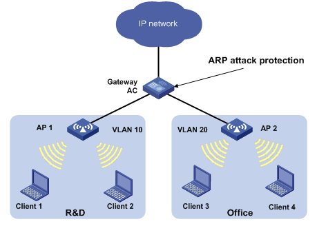
As shown in Figure 1, a LAN contains two areas: an R&D area in VLAN 10 and an office area in VLAN 20. Each area connects to the gateway (AC) through an AP.
A large number of ARP requests are detected in the office area and are considered a consequence of an IP flood attack. To prevent the attack, configure ARP source suppression and ARP blackhole routing.
Configuration considerations
If the attack packets have the same source address, you can enable the ARP source suppression feature as follows:
1. Enable ARP source suppression.
2. Set the threshold to 100. If the number of unresolvable IP packets received from a host within 5 seconds exceeds 100, the device stops resolving packets from the host until the 5 seconds elapse.
If the attack packets have different source addresses, enable the ARP blackhole routing feature on the AC.
Configuration procedure
# Enable ARP source suppression and set the threshold to 100.
<AC> system-view
[AC] arp source-suppression enable
[AC] arp source-suppression limit 100
# Enable ARP blackhole routing.
<AC> system-view
[AC] arp resolving-route enable
Configuring ARP packet rate limit
The ARP packet rate limit feature allows you to limit the rate of ARP packets to be delivered to the CPU. For example, if an attacker sends a large number of ARP packets to an ARP detection enabled device, the CPU of the device becomes overloaded because all the ARP packets are redirected to the CPU for inspection. As a result, the device is unable to provide other functions or can crash. To solve this problem, configure ARP packet rate limit.
Configure this feature when ARP detection, ARP snooping, or ARP fast-reply is enabled, or when ARP flood attacks are detected.
To configure ARP packet rate limit:
|
Step |
Command |
Remarks |
|
1. Enter system view. |
system-view |
N/A |
|
2. Enter Layer 2 Ethernet interface/Layer 2 aggregate interface/WLAN-ESS interface view. |
interface interface-type interface-number |
N/A |
|
3. Configure or disable ARP packet rate limit. |
arp rate-limit { disable | rate pps drop } |
Disabled by default. |
Configuring source MAC-based ARP attack detection
This feature checks the number of ARP packets received from the same MAC address within 5 seconds against a specific threshold. If the threshold is exceeded, the device adds the MAC address in an ARP attack entry.
Before the entry is aged out, the device handles the attack by using either of the following methods:
· Monitor—Only generates log messages.
· Filter—Generates log messages and filters out subsequent ARP packets from that MAC address.
After an ARP attack detection entry expires, ARP packets sourced from the MAC address in the entry can be processed correctly.
You can exclude the MAC addresses of some gateways and servers from detection. This feature does not inspect ARP packets from those devices even if they are attackers.
Only the ARP packets delivered to the CPU are checked.
To configure source MAC-based ARP attack detection:
|
Step |
Command |
Remarks |
|
1. Enter system view. |
system-view |
N/A |
|
2. Enable source MAC-based ARP attack detection and specify the handling method. |
arp anti-attack source-mac { filter | monitor } |
Disabled by default. |
|
3. Configure the threshold. |
arp anti-attack source-mac threshold threshold-value |
Optional. The threshold is 50. |
|
4. Set the lifetime for ARP attack entries. |
arp anti-attack source-mac aging-time time |
Optional. 300 seconds by default. |
|
5. Configure excluded MAC addresses. |
arp anti-attack source-mac exclude-mac mac-address&<1-10> |
Optional. No MAC address is excluded by default. |
Displaying and maintaining source MAC-based ARP attack detection
|
Task |
Command |
Remarks |
|
Display attacking MAC addresses detected by source MAC-based ARP attack detection. |
display arp anti-attack source-mac [ interface interface-type interface-number ] [ | { begin | exclude | include } regular-expression ] |
Available in any view. |
Source MAC-based ARP attack detection configuration example
Network requirements
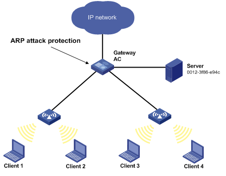
As shown in Figure 2, the hosts access the Internet through a gateway (AC). If malicious users send a large number of ARP requests to the gateway, the gateway might crash and cannot process requests from the clients. To solve this problem, configure source MAC-based ARP attack detection on the gateway.
Figure 2 Network diagram
Configuration considerations
An attacker might forge a large number of ARP packets by using the MAC address of a valid host as the source MAC address. To prevent such attacks, configure the gateway as follows:
1. Enable source MAC-based ARP attack detection and specify the handling method.
2. Set the threshold.
3. Set the lifetime for ARP attack entries.
4. Exclude the MAC address of the server from this detection
Configuration procedure
# Enable source MAC-based ARP attack detection and specify the handling method.
<AC> system-view
[AC] arp source-mac filter
# Set the threshold to 30.
[AC] arp source-mac threshold 30
# Set the lifetime for ARP attack entries to 60 seconds.
[AC] arp source-mac aging-time 60
# Exclude 0012-3f86-e94c from this detection.
[AC] arp source-mac exclude-mac 0012-3f86-e94c
Configuring ARP packet source MAC consistency check
This feature enables a gateway to filter out ARP packets whose source MAC address in the Ethernet header is different from the sender MAC address in the message body, so that the gateway can learn correct ARP entries.
To enable ARP packet source MAC address consistency check:
|
Step |
Command |
Remarks |
|
1. Enter system view. |
system-view |
N/A |
|
2. Enable ARP packet source MAC address consistency check. |
arp anti-attack valid-check enable |
Disabled by default. |
Configuring ARP active acknowledgement
Configure this feature on gateway devices to prevent user spoofing.
ARP active acknowledgement prevents a gateway from generating incorrect ARP entries. For more information about its working mechanism, see ARP Attack Protection Technology White Paper.
To configure ARP active acknowledgement:
|
Step |
Command |
Remarks |
|
1. Enter system view. |
system-view |
N/A |
|
2. Enable the ARP active acknowledgement feature. |
arp anti-attack active-ack enable |
Disabled by default. |
Configuring authorized ARP
Authorized ARP entries are generated based on the DHCP clients' address leases on the DHCP server or dynamic client entries on the DHCP relay agent.
With authorized ARP enabled, an interface is disabled from learning dynamic ARP entries to prevent user spoofing and allows only authorized clients to access network resources.
Follow these guidelines when you configure authorized ARP:
· This feature is only supported on VLAN interfaces.
· With the arp authorized enable command executed, an interface of a DHCP server (or a DHCP relay agent) that does not support authorized ARP is disabled from dynamically learning ARP entries and cannot generate authorized ARP entries.
· Static ARP entries can overwrite authorized ARP entries, and authorized ARP entries can overwrite dynamic ARP entries. But authorized ARP entries cannot overwrite static ARP entries, and dynamic ARP entries cannot overwrite authorized ARP entries.
For more information about DHCP server and DHCP relay agent, see Layer 3 Configuration Guide.
To enable authorized ARP:
|
Step |
Command |
Remarks |
|
1. Enter system view. |
system-view |
N/A |
|
2. Enter interface view. |
interface interface-type interface-number |
N/A |
|
3. Configure the DHCP server (or DHCP relay agent) to support authorized ARP. |
dhcp update arp |
Not configured by default. |
|
4. Enable authorized ARP on the interface. |
arp authorized enable |
Disabled by default. |
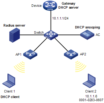
Authorized ARP configuration example (on a DHCP server)
Network requirements
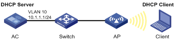
As shown in Figure 3, configure the DHCP server with an IP address pool of 10.1.1.0/24 on the AC.
Enable authorized ARP on VLAN-interface 10 of the AC to ensure user validity.
Configure the DHCP client to obtain an IP address from the DHCP server.
Configuration procedure
# Configure the client in VLAN 10 to connect the AC through the interface WLAN-ESS 1. (Details not shown.)
# Configure DHCP.
<AC> system-view
[AC] dhcp enable
[AC] dhcp server ip-pool 10
[AC-dhcp-pool-10] network 10.1.1.0 mask 255.255.255.0
[AC-dhcp-pool-10] gateway-list 10.1.1.1
[AC-dhcp-pool-10] quit
# Configure the IP address of VLAN-interface 10.
[AC] interface vlan-interface 10
[AC-Vlan-interface10] ip address 10.1.1.1 255.255.255.0
# Enable authorized ARP.
[AC-Vlan-interface10] dhcp update arp
[AC-Vlan-interface10] arp authorized enable
[AC-Vlan-interface10] quit
Verifying the configuration
# Display information about authorized ARP entry information on the AC.
[AC] display arp
Type: S-Static D-Dynamic A-Authorized
IP Address MAC Address VLAN ID Interface Aging Type
10.1.1.2 0000-8279-aa02 10 WLAN-DBSS1:52 N/A A
The output shows that the AC assigned the IP address 10.1.1.2 to the client.
The client must use the IP address and MAC address in the authorized ARP entry to communicate with the AC. Otherwise, the communication fails, and user validity is ensured.
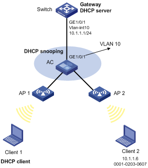
Authorized ARP configuration example (on a DHCP relay agent)
Network requirements
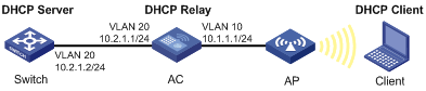
As shown in Figure 4, configure Switch as a DHCP server with an IP address pool of 10.1.1.0/24.
Configure the AC as a DHCP relay agent. Enable authorized ARP on VLAN-interface 10 of the AC to ensure user validity.
Configure Client as a DHCP client to obtain an IP address.
Configuration procedure
1. Configure DHCP server (Switch):
<Switch> system-view
[Switch] dhcp enable
[Switch] dhcp server ip-pool 10
[Switch-dhcp-pool-10] network 10.1.1.0 mask 255.255.255.0
[Switch-dhcp-pool-10] gateway-list 10.1.1.1
[Switch] interface vlan-interface 20
[Switch-Vlan-interface20] ip address 10.2.1.2 255.255.255.0
[Switch-Vlan-interface20] quit
[Switch] interface gigabitethernet 1/0/1
[Switch-GigabitEthernet1/0/1] port link-type hybrid
[Switch-GigabitEthernet1/0/1] port hybrid vlan 20 tagged
2. Configure the AC:
# Configure the client in VLAN 10 to connect the AC through the interface WLAN-ESS 1. (Details not shown.)
# Enable DHCP.
<AC> system-view
[AC] dhcp enable
# Configure the IP address of the DHCP server.
[AC] dhcp relay server-group 1 ip 10.2.1.2
# Configure the IP addresses of VLAN-interface 10 and VLAN-interface 20.
[AC] interface vlan-interface 10
[AC-Vlan-interface10] ip address 10.1.1.1 255.255.255.0
[AC-Vlan-interface10] quit
[AC] interface vlan-interface 20
[AC-Vlan-interface20] ip address 10.2.1.1 255.255.255.0
[AC-Vlan-interface20] quit
# Enable DHCP relay agent on VLAN-interface 10.
[AC] interface vlan-interface 10
[AC-Vlan-interface10] dhcp select relay
# Correlate VLAN-interface 10 to DHCP server group 1.
[AC-Vlan-interface10] dhcp relay server-select 1
# Enable authorized ARP.
[AC-Vlan-interface10] dhcp update arp
[AC-Vlan-interface10] arp authorized enable
[AC-Vlan-interface10] quit
Verifying the configuration
# Display authorized ARP entry information on the AC.
[AC] display arp
Type: S-Static D-Dynamic A-Authorized
IP Address MAC Address VLAN ID Interface Aging Type
10.1.1.2 0000-8279-aa02 10 WLAN-DBSS1:52 N/A A
The output shows that the AC assigned the IP address 10.1.1.2 to the client.
The client must use the IP address and MAC address in the authorized ARP entry to communicate with the AC. Otherwise, the communication fails, and the user validity is ensured.
Configuring ARP detection
ARP detection enables access devices to block ARP packets from unauthorized clients to prevent user spoofing and gateway spoofing attacks.
ARP detection provides the following functions:
· User validity check
· ARP packet validity check
· ARP restricted forwarding
If both ARP packet validity check and user validity check are enabled, ARP packet validity check applies first, and then user validity check applies.
ARP detection does not check ARP packets received from ARP trusted ports.
Configuring user validity check
After you enable this feature, the device checks user validity as follows:
1. Upon receiving an ARP packet from an ARP untrusted port, the device compares the sender IP and MAC addresses of the ARP packet against user validity check rules. If a matching rule is found, the ARP packet is processed according to the rule.
2. If no matching rule is found, the device compares the ARP packet's sender IP and MAC addresses against the DHCP snooping entries and 802.1X security entries. If a match is found in any of the entries, the ARP packet is considered valid and is forwarded.
3. If no match is found, the ARP packet is considered invalid and is discarded.
Dynamic DHCP snooping entries are automatically generated by DHCP snooping. For more information, see Layer 3 Configuration Guide.
802.1X security entries are generated by 802.1X. After a client passes 802.1X authentication and uploads its IP address to an ARP detection-enabled device, the device automatically generates an 802.1X security entry. For more information, see "Configuring 802.1X."
To configure user validity check:
|
Step |
Command |
Remarks |
|
1. Enter system view. |
system-view |
N/A |
|
2. Configure a user validity check rule. |
arp detection id-number { deny | permit } ip { any | ip-address [ ip-address-mask ] } mac { any | mac-address [ mac-address-mask ] } [ vlan vlan-id ] |
Optional. Not configured by default. |
|
3. Enter VLAN view. |
vlan vlan-id |
N/A |
|
4. Enable ARP detection. |
arp detection enable |
Disabled by default. |
|
5. Return to system view. |
quit |
N/A |
|
6. Enter Layer 2 Ethernet interface view/Layer 2 aggregate interface/WLAN-ESS interface view. |
interface interface-type interface-number |
N/A |
|
7. Configure the port as a trusted port that is excluded from ARP detection. |
arp detection trust |
Optional. A port is an untrusted port by default. |
At least a user validity check rule, a DHCP snooping entry, or an 802.1X security entry must be available to perform user validity check. Otherwise, ARP packets received from ARP untrusted ports are discarded.
Configuring ARP packet validity check
Perform this task to enable validity check for ARP packets received on untrusted ports and specify the following objects to be checked:
· src-mac—Checks whether the sender MAC address in the message body is identical to the source MAC address in the Ethernet header. If they are identical, the packet is forwarded. Otherwise, the packet is discarded.
· dst-mac—Checks the target MAC address of ARP replies. If the target MAC address is all-zero, all-one, or inconsistent with the destination MAC address in the Ethernet header, the packet is considered invalid and discarded.
· ip—Checks the sender and target IP addresses of ARP replies, and the sender IP address of ARP requests. All-zero, all-one, or multicast IP addresses are considered invalid and the corresponding packets are discarded.
To configure ARP packet validity check:
|
Step |
Command |
Remarks |
|
1. Enter system view. |
system-view |
N/A |
|
2. Enter VLAN view. |
vlan vlan-id |
N/A |
|
3. Enable ARP detection. |
arp detection enable |
Disabled by default. |
|
4. Return to system view. |
quit |
N/A |
|
5. Enable ARP packet validity check and specify the objects to be checked. |
arp detection validate { dst-mac | ip | src-mac } * |
Disabled by default. |
|
6. Enter Layer 2 Ethernet interface view/Layer 2 aggregate interface/WLAN-ESS interface view. |
interface interface-type interface-number |
N/A |
|
7. Configure the port as a trusted port that is excluded from ARP detection. |
arp detection trust |
Optional. The port is an untrusted port by default. |
Configuring ARP restricted forwarding
ARP restricted forwarding controls the forwarding of ARP packets that are received on untrusted interfaces and have passed user validity check as follows:
· If the packets are ARP requests, they are forwarded through the trusted interface.
· If the packets are ARP replies, they are forwarded according to their destination MAC address. If no match is found in the MAC address table, they are forwarded through the trusted interface.
Before configuring this feature, configure user validity check.
To enable ARP restricted forwarding:
|
Step |
Command |
Remarks |
|
1. Enter system view. |
system-view |
N/A |
|
2. Enter VLAN view. |
vlan vlan-id |
N/A |
|
3. Enable ARP restricted forwarding. |
arp restricted-forwarding enable |
Disabled by default. |
Displaying and maintaining ARP detection
|
Task |
Command |
Remarks |
|
Display the VLANs enabled with ARP detection. |
display arp detection [ | { begin | exclude | include } regular-expression ] |
Available in any view. |
|
Display the ARP detection statistics. |
display arp detection statistics [ interface interface-type interface-number ] [ | { begin | exclude | include } regular-expression ] |
Available in any view. |
|
Clear the ARP detection statistics. |
reset arp detection statistics [ interface interface-type interface-number ] |
Available in user view. |
User validity check configuration example
Network requirements
As shown in Figure 5:
· Configure the DHCP server on the switch.
· Configure 802.1X on the AC.
· Enable ARP detection in VLAN 10 to check user validity based on 802.1X entries.
· Configure Client 1 and Client 2 as 802.1X users.
Configuration procedure
1. Add the port connecting the AC to VLAN 10, and configure the IP address of VLAN-interface 10 on the switch. (Details not shown.)
2. Configure DHCP address pool 0 on the switch.
<Switch> system-view
[Switch] dhcp enable
[Switch] dhcp server ip-pool 0
[Switch-dhcp-pool-0] network 10.1.1.0 mask 255.255.255.0
3. Configure Client 1 and Client 2 as 802.1X clients and configure them to upload IP addresses for ARP detection. (Details not shown.)
4. Configure the RADIUS server. (Details not shown.)
5. Configure the AC:
# Create a RADIUS scheme named rad.
[AC] radius scheme rad
# Specify the primary authentication server with IP address 8.1.1.16.
[AC-radius-rad] primary authentication 8.1.1.16
# Specify the primary accounting server with IP address 8.1.1.16.
[AC-radius-rad] primary accounting 8.1.1.16
# Set the shared key for secure authentication communication to plaintext expert.
[AC-radius-rad] key authentication expert
# Set the shared key for secure accounting communication to plaintext expert.
[AC-radius-rad] key accounting expert
# Configure the RADIUS server type of RADIUS scheme rad as extended.
[AC-radius-rad] server-type extended
# Remove domain names from the usernames sent to the RADIUS server.
[AC-radius-rad] user-name-format without-domain
[AC-radius-rad] quit
# Create an ISP domain named imc and enter ISP domain view.
[AC] domain imc
# Configure the ISP domain to use RADIUS scheme rad for authentication, authorization, and accounting of LAN users.
[AC-isp-imc] authentication lan-access radius-scheme rad
[AC-isp-imc] authorization lan-access radius-scheme rad
[AC-isp-imc] accounting lan-access radius-scheme rad
[AC-isp-imc] quit
# Configure the ISP domain imc as the default ISP domain.
[AC] domain default enable imc
# Enable port security.
[AC] port-security enable
# Configure EAP relay.
[AC] dot1x authentication-method eap
# Enable wireless 802.1X authentication on the AC.
<AC> system-view
[AC] interface wlan-ess 0
[AC-WLAN-ESS0] port access vlan 10
[AC-WLAN-ESS0] port-security port-mode userlogin-secure-ext
[AC-WLAN-ESS0] port-security tx-key-type 11key
[AC-WLAN-ESS0] undo dot1x multicast-trigger
[AC-WLAN-ESS0] undo dot1x handshake
[AC-WLAN-ESS0] quit
# Configure a crypto-type WLAN service template, set the service set identifier (SSID) to dot1x, and bind the WLAN-ESS port to the template.
[AC] wlan service-template 1 crypto
[AC-wlan-st-1] ssid dot1x
[AC-wlan-st-1] bind wlan-ess 0
# Enable open system authentication.
[AC-wlan-st-1] authentication-method open-system
# Enable the tkip cipher suite.
[AC-wlan-st-1] cipher-suite tkip
# Enable the WPA-IE in the beacon and probe responses.
[AC-wlan-st-1] security-ie wpa
[AC-wlan-st-1] service-template enable
[AC-wlan-st-1] quit
# Create AP template 2100 with the model WA3628i-AGN and serial number 210235A29G007C000020.
[AC] wlan ap 2100 model WA3628i-AGN
[AC-wlan-ap-2100] serial-id 210235A29G007C000020
# Bind the WLAN service template to radio 1, and enable the radio.
[AC-wlan-ap-2100] radio 1
[AC-wlan-ap-2100-radio-1] service-template 1
[AC-wlan-ap-2100-radio-1] radio enable
# The ports connecting the AC and APs reside in VLAN 1 by default. Configure the IP address for the VLAN interface on the AC and APs. (Details not shown.)
# Enable ARP detection for VLAN 10 to check user validity based on 802.1X entries.
[AC] vlan 10
[AC-vlan10] arp detection enable
# Configure the upstream port as a trusted port. The downstream WLAN-ESS port uses the default setting untrusted.
[AC-vlan10] interface gigabitethernet 1/0/1
[AC-GigabitEthernet1/0/1] arp detection trust
[AC-GigabitEthernet1/0/1] quit
After the configuration, the AC checks ARP packets received on WLAN-ESS 0 against 802.1X entries.
User validity check and ARP packet validity check configuration example
Network requirements
As shown in Figure 6:
· Configure the switch as a DHCP server.
· Enable DHCP snooping on the AC.
· Configure Client 1 as a DHCP client. Configure Client 2's IP address 10.1.1.6 and MAC address 0001-0203-0607.
· Enable user validity check and ARP packet validity check in VLAN 10.
Configuration procedure
1. Add the port connecting the AC to VLAN 10, and configure the IP address of VLAN-interface 10 on the switch. (Details not shown.)
2. Configure DHCP address pool 0 on the switch.
<Switch> system-view
[Switch] dhcp enable
[Switch] dhcp server ip-pool 0
[Switch-dhcp-pool-0] network 10.1.1.0 mask 255.255.255.0
3. Configure DHCP clients Client 1 and Client 2. (Details not shown.)
4. Configure the AC:
# Create a WLAN-ESS interface and add the interface to VLAN 10.
<AC> system-view
[AC] interface wlan-ess 0
[AC-WLAN-ESS0] port access vlan 10
[AC-WLAN-ESS0] quit
# Configure a clear-type WLAN service template, set the SSID to test, and bind the WLAN-ESS interface to the template.
[AC] wlan service-template 1 clear
[AC-wlan-st-1] ssid test
[AC-wlan-st-1] bind wlan-ess 0
[AC-wlan-st-1] service-template enable
# Create AP template 2100 with the model WA3628i-AGN and serial number 210235A29G007C000020.
[AC] wlan ap 2100 model WA3628i-AGN
[AC-wlan-ap-2100] serial-id 210235A29G007C000020
# Bind the WLAN service template to radio 1, and enable the radio.
[AC-wlan-ap-2100] radio 1
[AC-wlan-ap-2100-radio-1] service-template 1
[AC-wlan-ap-2100-radio-1] radio enable
# The ports connecting the AC and APs reside in VLAN 1 by default. Configure the IP address of the VLAN interface on the AC and APs. (Details not shown.)
# Enable DHCP snooping.
<AC> system-view
[AC] dhcp-snooping
[AC] interface gigabitethernet 1/0/1
[AC-GigabitEthernet1/0/1] dhcp-snooping trust
[AC-GigabitEthernet1/0/1] quit
# Enable ARP detection for VLAN 10 to check user validity.
[AC] vlan 10
[AC-vlan10] arp detection enable
# Configure the upstream port as a trusted port and the downstream ports as untrusted ports. By default, a port is an untrusted port.
[AC-vlan10] interface gigabitethernet 1/0/1
[AC-GigabitEthernet1/0/1] arp detection trust
[AC-GigabitEthernet1/0/1] quit
# Enable ARP packet validity check.
[AC] arp detection validate dst-mac ip src-mac
After the configuration, the AC will first check the validity of ARP packets received on the WLAN-ESS interface, and then check the ARP packets against DHCP snooping entries.
Configuring ARP gateway protection
Configure this feature on interfaces not connected with the gateway to prevent gateway spoofing attacks.
When such a port receives an ARP packet, it checks whether the sender IP address in the packet is consistent with that of any protected gateway. If yes, it discards the packet. If not, it handles the packet correctly.
Follow these guidelines when you configure ARP gateway protection:
· You can enable ARP gateway protection for up to eight gateways on a port.
· Commands arp filter source and arp filter binding cannot be both configured on a port.
· If ARP gateway protection works with ARP detection, ARP snooping, and ARP fast-reply, ARP gateway protection applies first.
To configure ARP gateway protection:
|
Step |
Command |
Remarks |
|
|
1. Enter system view. |
system-view |
N/A |
|
|
2. Enter Layer 2 Ethernet interface or WLAN-ESS interface view. |
interface interface-type interface-number |
N/A |
|
|
3. Enable ARP gateway protection for a specific gateway. |
arp filter source ip-address |
Disabled by default. |
|
Configuration example
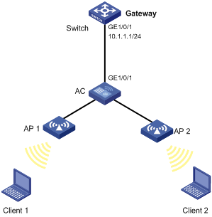
Network requirements
As shown in Figure 7, Client 2 launches gateway spoofing attacks to AC. As a result, traffic that AC intends to send to Switch is sent to Client 2.
Configure AC to block such attacks.
Configuration procedure
# Configure the clients to connect the AC through interface WLAN-ESS 0. (Details not shown.)
# Configure ARP gateway protection on the AC.
<AC> system-view
[AC] interface wlan-ess 0
[AC-WLAN-ESS0] arp filter source 10.1.1.1
[AC-WLAN-ESS0] quit
After the configuration is complete, the AC discards the ARP packets whose source IP address is that of the gateway.
Configuring ARP filtering
The ARP filtering feature can prevent gateway spoofing and user spoofing attacks.
An interface enabled with this feature checks the sender IP and MAC addresses in a received ARP packet against permitted entries. If a match is found, the packet is handled correctly. If not, the packet is discarded.
Follow these guidelines when you configure ARP filtering:
· You can configure up to eight permitted entries on an interface.
· The arp filter source and arp filter binding command cannot be both configured on an interface.
· If ARP filtering works with ARP detection, ARP snooping, and ARP fast-reply, ARP filtering applies first.
To configure ARP filtering:
|
Step |
Command |
Remarks |
|
1. Enter system view. |
system-view |
N/A |
|
2. Enter Layer 2 Ethernet interface or WLAN-ESS interface view. |
interface interface-type interface-number |
N/A |
|
3. Enable ARP filtering and configure a permitted entry. |
arp filter binding ip-address mac-address |
Disabled by default. |
Configuration example
Network requirements
As shown in Figure 8, the IP and MAC addresses of Client 1 are 10.1.1.2 and 000f-e349-1233. The IP and MAC addresses of Client 2 are 10.1.1.3 and 000f-e349-1234.
Configure ARP filtering on GigabitEthernet 1/0/1 of AC to permit ARP packets from the two hosts only.

Configuration procedure
# Configure wireless services and the AP, and configure the radio port as WLAN-ESS 0. (Details not shown.)
# Configure ARP filtering on the AC.
<AC> system-view
[AC] interface wlan-ess 0
[AC-WLAN-ESS0] arp filter binding 10.1.1.2 000f-e349-1233
[AC-WLAN-ESS0] arp filter binding 10.1.1.3 000f-e349-1234
After the configuration is complete, GigabitEthernet 1/0/1 permits ARP packets from Client 1 and Client 2, and discards other ARP packets.