- Table of Contents
-
- H3C Low-End Ethernet Switches Configuration Guide(V1.01)
- 01-Login Configuration Guide
- 02-VLAN Configuration Guide
- 03-IP Address Configuration Guide
- 04-Voice VLAN Configuration Guide
- 05-GVRP Configuration Guide
- 06-Ethernet Interface Basic Configuration Guide
- 07-Link Aggregation Configuration Guide
- 08-Port Isolation Configuration Guide
- 09-Port Security Configuration Guide
- 10-Port Binding Configuration Guide
- 11-MAC Address Table Management Configuration Guide
- 12-DLDP Configuration Guide
- 13-Auto Detect Configuration Guide
- 14-MSTP Configuration Guide
- 15-Routing Configuration Guide
- 16-Multicast Configuration Guide
- 17-802.1x Configuration Guide
- 18-AAA Configuration Guide
- 19-MAC Authentication Configuration Guide
- 20-VRRP Configuration Guide
- 21-ARP Configuration Guide
- 22-DHCP Configuration Guide
- 23-ACL Configuration Guide
- 24-QoS-QoS Profile Configuration Guide
- 25-Web Cache Redirection Configuration Guide
- 26-Mirroring Configuration Guide
- 27-IRF Configuration Guide
- 28-Cluster Configuration Guide
- 29-PoE-PoE Profile Configuration Guide
- 30-UDP Helper Configuration Guide
- 31-SNMP-RMON Configuration Guide
- 32-NTP Configuration Guide
- 33-SSH Configuration Guide
- 34-FTP and TFTP Configuration Guide
- 35-Information Center Configuration Guide
- 36-VLAN-VPN Configuration Guide
- 37-HWPing Configuration Guide
- 38-DNS Configuration Guide
- 39-Access Management Configuration Guide
- 40-Web Authentication Configuration Guide
- 41-IPv6 Management Configuration Guide
- 42-Smart link - Monitor Link Configuration Guide
- 43-VLAN Mapping Configuration Guide
- Related Documents
-
| Title | Size | Download |
|---|---|---|
| 33-SSH Configuration Guide | 945.47 KB |
Table of Contents
Configuring the Switch to Act as the SSH Server and Use Password Authentication
Networking and Configuration Requirements
Configuring the Switch to Act as the SSH Server and Use RSA Authentication
Networking and Configuration Requirements
Configuring the Switch to Act as the SSH Client and Use Password Authentication
Networking and Configuration Requirements
Configuring the Switch to Act as the SSH Client and Use RSA Authentication
Networking and Configuration Requirements
Configuring the Switch to Act as the SSH Client and Not to Support First-Time Authentication
Networking and Configuration Requirements
Networking and Configuration Requirements
When Switch Acts as Server for Password Authentication
Networking and Configuration Requirements
When Switch Acts as Server for Publickey Authentication
Networking and Configuration Requirements
When Switch Acts as Client for Password Authentication
Networking and Configuration Requirements
When Switch Acts as Client for Publickey Authentication
Networking and Configuration Requirements
When Switch Acts as Client and First-Time Authentication is not Supported
Networking and Configuration Requirements
Networking and Configuration Requirements
![]()
The asymmetric key algorithm of DSA is now available on the H3C low-end Ethernet switches. This configuration guide provides the relevant guidelines from sections When Switch Acts as Server for Password Authentication to SFTP Configuration.
Configuring the Switch to Act as the SSH Server and Use Password Authentication
Network Diagram
Figure 1-1 Network diagram for configuring the switch to act as the SSH server and use password authentication
Networking and Configuration Requirements
In scenarios where users log into a switch over an insecure network, SSH can be used to ensure the security of data exchange to the maximum extent. As shown inFigure 1-1, establish an SSH connection between the host (SSH client) and the switch (SSH server) for secure data exchange. The host runs SSH2 client software. Password authentication is required.
Applicable Product Matrix
|
Product series |
Software version |
Hardware version |
|
S5600 series |
Release 1510 |
All versions |
|
S3600-SI/EI series |
Release 1510 |
All versions |
|
S3100-C-SI series S3100-T-SI series |
Release 0011 |
All versions |
|
S3100-52P |
Release 1500 |
S3100-52P |
Configuration Procedure
l Configure the SSH server
# Create a VLAN interface on the switch and assign an IP address for it. The SSH client will use this address as the destination for SSH connection.
<Switch> system-view
[Switch] interface vlan-interface 1
[Switch-Vlan-interface1] ip address 192.168.0.1 255.255.255.0
[Switch-Vlan-interface1] quit
# Generate an RSA key pair.
[Switch] rsa local-key-pair create
# Set the authentication mode for the user interfaces to AAA.
[Switch] user-interface vty 0 4
[Switch-ui-vty0-4] authentication-mode scheme
# Enable the user interfaces to support SSH.
[Switch-ui-vty0-4] protocol inbound ssh
[Switch-ui-vty0-4] quit
# Create local user client001, and set the authentication password to abc, protocol type to SSH, and command privilege level to 3 for the user.
[Switch] local-user client001
[Switch-luser-client001] password simple abc
[Switch-luser-client001] service-type ssh level 3
[Switch-luser-client001] quit
# Specify the authentication method of user client001 as password.
[Switch] ssh user client001 authentication-type password
l Configure the SSH client
# Configure an IP address (192.168.0.2 in this case) for the SSH client.
This IP address and that of the VLAN interface on the switch must be in the same network segment.
# Configure the SSH client software to establish a connection to the SSH server.
Take SSH client software PuTTY v0.58 as an example:
1) Run PuTTY.exe to enter the following configuration interface.
Figure 1-2 SSH client configuration interface

In the Host Name (or IP address) text box, enter the IP address of the SSH server.
2) From the category on the left pane of the window, select SSH under Connection. The window as shown in Figure 1-3 appears.
Figure 1-3 SSH client configuration interface 2
Under Protocol options, select 2 from Preferred SSH protocol version.
3) As shown inFigure 1-3, click Open. If the connection is normal, you can enter the username client001 and password abc at prompt. Once authentication succeeds, you will log onto the server.
Complete Configuration
l Configure the SSH server
#
local-user client001
password simple abc
service-type ssh
level 3
#
interface Vlan-interface1
ip address 192.168.0.1 255.255.255.0
#
ssh user client001 authentication-type password
ssh user client001 service-type stelnet
#
user-interface vty 0 4
authentication-mode scheme
protocol inbound ssh
Precautions
After configuring the user interfaces to support SSH, be sure to configure the user interfaces to use AAA authentication by using the authentication-mode scheme command and configure the default domain to use the AAA method of local.
Configuring the Switch to Act as the SSH Server and Use RSA Authentication
Network Diagram
Figure 1-4 Network diagram for configuring the switch to act as the SSH server and use RSA authentication
Networking and Configuration Requirements
In scenarios where users log into a switch over an insecure network, SSH can be used to ensure the security of data exchange to the maximum extent. As shown inFigure 1-4, establish an SSH connection between the host (SSH client) and the switch (SSH server) for secure data exchange. The host runs SSH2 client software. RSA authentication is required.
Applicable Product Matrix
|
Product series |
Software version |
Hardware version |
|
S5600 series |
Release 1510 |
All versions |
|
S3600-SI/EI series |
Release 1510 |
All versions |
|
S3100-C-SI series S3100-T-SI series |
Release 0011 |
All versions |
|
S3100-52P |
Release 1500 |
S3100-52P |
Configuration Procedure
l Configure the SSH server
# Create a VLAN interface on the switch and assign an IP address for it. The SSH client will use this address as the destination for SSH connection.
<Switch> system-view
[Switch] interface vlan-interface 1
[Switch-Vlan-interface1] ip address 192.168.0.1 255.255.255.0
[Switch-Vlan-interface1] quit
# Generate an RSA key pair.
[Switch] rsa local-key-pair create
# Set the authentication mode for the user interfaces to AAA.
[Switch] user-interface vty 0 4
[Switch-ui-vty0-4] authentication-mode scheme
# Enable the user interfaces to support SSH.
[Switch-ui-vty0-4] protocol inbound ssh
# Set the client’s command privilege level to 3.
[Switch-ui-vty0-4] user privilege level 3
[Switch-ui-vty0-4] quit
# Configure the authentication method of the SSH client named client001 as RSA.
[Switch] ssh user client001 authentication-type rsa
![]()
Before performing the following steps, you must generate an RSA key pair by using the client software on the client, save the public key in a file named public, and then upload the file to the SSH server through FTP or TFTP. For details, refer to “Configure the SSH client” below.
# Import the client’s public key named Switch001 from file public.
[Switch] rsa peer-public-key Switch001 import sshkey public
# Assign the public key Switch001 to client client001.
[Switch] ssh user client001 assign rsa-key Switch001
l Configure the SSH client
# Generate an RSA key pair, taking PuTTYGen as an example.
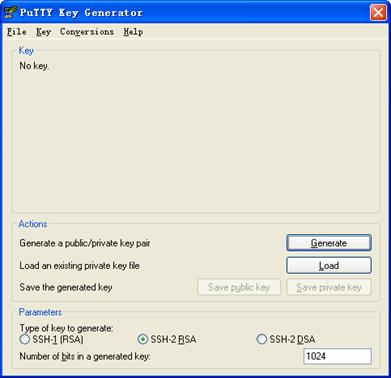
1) Run PuTTYGen.exe, choose SSH-2 RSA and click Generate.
Figure 1-5 Client key pair generation interface 1

![]()
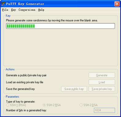
During the generation process, you must move the mouse continuously and keep the mouse off the green process bar shown inFigure 1-6. Otherwise, the process bar stops moving and the key pair generation process is stopped.
Figure 1-6 Client key pair generation interface 2
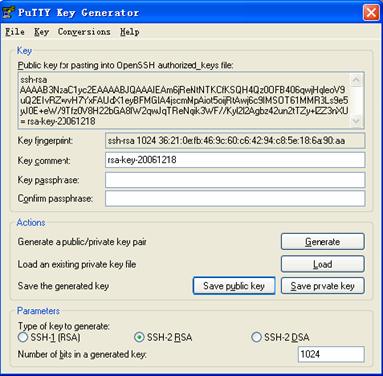
After the key pair is generated, click Save public key and enter the name of the file for saving the public key (public in this case).
Figure 1-7 Client key pair generation interface 3

Likewise, to save the private key, click Save private key. A warning window pops up to prompt you whether to save the private key without any protection. Click Yes and enter the name of the file for saving the private key (private.ppk in this case).
Figure 1-8 Client key pair generation interface 4

# Configure the SSH client software to establish a connection to the SSH server.
Take SSH client software PuTTY v0.58 as an example:
2) Run PuTTY.exe to enter the following configuration interface.
Figure 1-9 SSH client configuration interface 1

In the Host Name (or IP address) text box, enter the IP address of the SSH server.
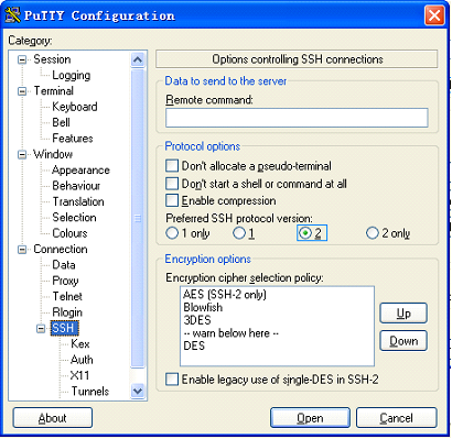
3) From the category on the left pane of the window, select SSH under Connection. The window as shown in Figure 1-10 appears.
Figure 1-10 SSH client configuration interface 2
Under Protocol options, select 2 from Preferred SSH protocol version.
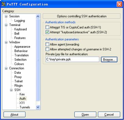
4) From the category, select Connection/SSH/Auth. The following window appears.
Figure 1-11 SSH client configuration interface 2
Click Browse… to bring up the file selection window, navigate to the private key file and click OK.
5) In the window shown inFigure 1-11, click Open. If the connection is normal, you will be prompted to enter the username.
Complete Configuration
l Configure the SSH server
#
interface Vlan-interface1
ip address 192.168.0.1 255.255.255.0
#
ssh user client001 assign rsa-key Switch001
ssh user client001 authentication-type rsa
ssh user client001 service-type stelnet
#
user-interface vty 0 4
authentication-mode scheme
user privilege level 3
protocol inbound ssh
Precautions
When acting as an SSH server, an S3100-SI series Ethernet switch does not support configuring the client host public key by importing from a public key file. You need to configure it manually.
Configuring the Switch to Act as the SSH Client and Use Password Authentication
Network Diagram
Figure 1-12 Network diagram for configuring the switch to act as the SSH client and use password authentication
Networking and Configuration Requirements
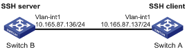
In scenarios where users log into a switch over an insecure network by using another switch, SSH can be used to ensure the security of data exchange to the maximum extent. As shown inFigure 1-12:
l Switch A acts as the SSH client and the login username is client001.
l Switch B acts as the SSH server, whose IP address is 10.165.87.136.
l Password authentication is required.
Applicable Product Matrix
|
Product series |
Software version |
Hardware version |
|
S5600 series |
Release 1510 |
All versions |
|
S3600-SI/EI series |
Release 1510 |
All versions |
|
S3100-C-SI series S3100-T-SI series |
Release 0011 |
All versions |
|
S3100-52P |
Release 1500 |
S3100-52P |
Configuration Procedure
l Configure Switch B
# Create a VLAN interface on the switch and assign an IP address for it. The SSH client will use this address as the destination for SSH connection.
<SwitchB> system-view
[SwitchB] interface vlan-interface 1
[SwitchB-Vlan-interface1] ip address 10.165.87.136 255.255.255.0
[SwitchB-Vlan-interface1] quit
# Generate an RSA key pair.
[SwitchB] rsa local-key-pair create
# Set the authentication mode for the user interfaces to AAA.
[SwitchB] user-interface vty 0 4
[SwitchB-ui-vty0-4] authentication-mode scheme
# Enable the user interfaces to support SSH.
[SwitchB-ui-vty0-4] protocol inbound ssh
[SwitchB-ui-vty0-4] quit
# Create local user client001, and set the authentication password to abc, protocol type to SSH, and command privilege level to 3 for the client.
[SwitchB] local-user client001
[SwitchB-luser-client001] password simple abc
[SwitchB-luser-client001] service-type ssh level 3
[SwitchB-luser-client001] quit
# Specify the authentication method of user client001 as password.
[SwitchB] ssh user client001 authentication-type password
l Configure Switch A
# Create a VLAN interface on the switch and assign an IP address for it. This address will serve as the SSH client’s address for SSH connection.
<SwitchA> system-view
[SwitchA] interface vlan-interface 1
[SwitchA-Vlan-interface1] ip address 10.165.87.137 255.255.255.0
[SwitchA-Vlan-interface1] quit
# Establish a connection to the server 10.165.87.136.
[SwitchA] ssh2 10.165.87.136
Username: client001
Trying 10.165.87.136 ...
Press CTRL+K to abort
Connected to 10.165.87.136 ...
The Server is not authenticated. Do you continue to access it?(Y/N):y
Do you want to save the server's public key?(Y/N):n
Enter password:
**********************************************************************
* Copyright(c) 2004-2007 Hangzhou H3C Tech. Co., Ltd. All rights reserved.*
* Without the owner's prior written consent, *
* no decompiling or reverse-engineering shall be allowed. *
**********************************************************************
<SwitchB>
Complete Configuration
l Configure Switch B
#
local-user client001
password simple abc
service-type ssh
level 3
#
interface Vlan-interface1
ip address 10.165.87.136 255.255.255.0
#
ssh user client001 authentication-type password
ssh user client001 service-type stelnet
#
user-interface vty 0 4
authentication-mode scheme
protocol inbound ssh
l Configure Switch A
#
interface Vlan-interface1
ip address 10.165.87.137 255.255.255.0
#
Precautions
After configuring the user interfaces to support SSH, be sure to configure the user interfaces to use AAA authentication by using the authentication-mode scheme command and configure the default domain to use the AAA method of local.
Configuring the Switch to Act as the SSH Client and Use RSA Authentication
Network Diagram
Figure 1-13 Network diagram for configuring the switch to act as the SSH client and use RSA authentication
Networking and Configuration Requirements
In scenarios where users log into a switch over an insecure network by using another switch, SSH can be used to ensure the security of data exchange to the maximum extent. As shown inFigure 1-13:
l Switch A acts as the SSH client and the login username is client001.
l Switch B acts as the SSH server, whose IP address is 10.165.87.136.
l RSA authentication is required.
Applicable Product Matrix
|
Product series |
Software version |
Hardware version |
|
S5600 series |
Release 1510 |
All versions |
|
S3600-SI/EI series |
Release 1510 |
All versions |
|
S3100-C-SI series S3100-T-SI series |
Release 0011 |
All versions |
|
S3100-52P |
Release 1500 |
S3100-52P |
Configuration Procedure
l Configure Switch B
# Create a VLAN interface on the switch and assign an IP address for it. The SSH client will use this address as the destination for SSH connection.
<SwitchB> system-view
[SwitchB] interface vlan-interface 1
[SwitchB-Vlan-interface1] ip address 10.165.87.136 255.255.255.0
[SwitchB-Vlan-interface1] quit
# Generate an RSA key pair.
[SwitchB] rsa local-key-pair create
# Set the authentication mode for the user interfaces to AAA.
[SwitchB] user-interface vty 0 4
[SwitchB-ui-vty0-4] authentication-mode scheme
# Enable the user interfaces to support SSH.
[SwitchB-ui-vty0-4] protocol inbound ssh
# Set the client’s command privilege level to 3.
[SwitchB-ui-vty0-4] user privilege level 3
[SwitchB-ui-vty0-4] quit
# Configure the authentication method of the SSH client named client001 as RSA.
[SwitchB] ssh user client001 authentication-type rsa
![]()
After generating an RSA key pair on the SSH client, manually configure the RSA public key on the SSH server. For details, refer to “Configure Switch A” below.
# Configure the client public key Switch001.
[SwitchB] rsa peer-public-key Switch001
RSA public key view: return to System View with "peer-public-key end".
[SwitchB-rsa-public-key] public-key-code begin
RSA key code view: return to last view with "public-key-code end".
[SwitchB-rsa-key-code] 3047
[SwitchB-rsa-key-code] 0240
[SwitchB-rsa-key-code] C8969B5A 132440F4 0BDB4E5E 40308747 804F608B
[SwitchB-rsa-key-code] 349EBD6A B0C75CDF 8B84DBE7 D5E2C4F8 AED72834
[SwitchB-rsa-key-code] 74D3404A 0B14363D D709CC63 68C8CE00 57C0EE6B
[SwitchB-rsa-key-code] 074C0CA9
[SwitchB-rsa-key-code] 0203
[SwitchB-rsa-key-code] 010001
[SwitchB-rsa-key-code] public-key-code end
[SwitchB-rsa-public-key] peer-public-key end
[SwitchB]
# Assign the public key Switch001 to client client001.
[SwitchB] ssh user client001 assign rsa-key Switch001
l Configure Switch A
# Create a VLAN interface on the switch and assign an IP address for it. This address will serve as the SSH client’s address for SSH connection.
<SwitchA> system-view
[SwitchA] interface vlan-interface 1
[SwitchA-Vlan-interface1] ip address 10.165.87.137 255.255.255.0
[SwitchA-Vlan-interface1] quit
# Generate an RSA key pair.
[SwitchA] rsa local-key-pair create
# Display the host public key.
<SwitchA> display rsa local-key-pair public
=====================================================
Time of Key pair created: 05:15:04 2006/12/08
Key name: H3C_Host
Key type: RSA encryption Key
=====================================================
Key code:
3047
0240
C8969B5A 132440F4 0BDB4E5E 40308747 804F608B
349EBD6A B0C75CDF 8B84DBE7 D5E2C4F8 AED72834
74D3404A 0B14363D D709CC63 68C8CE00 57C0EE6B
074C0CA9
0203
010001
Omitted
![]()
After generating a key pair on a client, you need to manually configure the host public key on the server and have the configuration on the server done before continuing configuration on the client.
# Establish a connection to the server 10.165.87.136.
[SwitchA] ssh2 10.165.87.136
Username: client001
Trying 10.165.87.136 ...
Press CTRL+K to abort
Connected to 10.165.87.136 ...
The Server is not authenticated. Do you continue to access it?(Y/N):y
Do you want to save the server's public key?(Y/N):n
**********************************************************************
* Copyright(c) 2004-2007 Hangzhou H3C Tech. Co., Ltd. All rights reserved.*
* Without the owner's prior written consent, *
* no decompiling or reverse-engineering shall be allowed. *
**********************************************************************
<SwitchB>
Complete Configuration
l Configure Switch B
#
rsa peer-public-key Switch001
public-key-code begin
3047
0240
C8969B5A 132440F4 0BDB4E5E 40308747 804F608B 349EBD6A B0C75CDF 8B84DBE7
D5E2C4F8 AED72834 74D3404A 0B14363D D709CC63 68C8CE00 57C0EE6B 074C0CA9
0203
010001
public-key-code end
peer-public-key end
#
interface Vlan-interface1
ip address 10.165.87.136 255.255.255.0
#
ssh user client001 assign rsa-key Switch001
ssh user client001 authentication-type rsa
ssh user client001 service-type stelnet
#
user-interface vty 0 4
authentication-mode scheme
user privilege level 3
protocol inbound ssh
l Configure Switch A
#
interface Vlan-interface1
ip address 10.165.87.137 255.255.255.0
#
Precautions
None
Configuring the Switch to Act as the SSH Client and Not to Support First-Time Authentication
Network Diagram
Figure 1-14 Network diagram for configuring the switch to act as the SSH client and not to support first-time authentication
Networking and Configuration Requirements
In scenarios where users log into a switch over an insecure network by using another switch, SSH can be used to ensure the security of data exchange to the maximum extent. As shown inFigure 1-14:
l Switch A acts as the SSH client and the login username is client001.
l Switch B acts as the SSH server, whose IP address is 10.165.87.136.
l RSA authentication is required.
Applicable Product Matrix
|
Product series |
Software version |
Hardware version |
|
S5600 series |
Release 1510 |
All versions |
|
S3600-SI/EI series |
Release 1510 |
All versions |
|
S3100-C-SI series S3100-T-SI series |
Release 0011 |
All versions |
|
S3100-52P |
Release 1500 |
S3100-52P |
Configuration Procedure
l Configure Switch B
# Create a VLAN interface on the switch and assign an IP address for it. The SSH client will use this address as the destination for SSH connection.
<SwitchB> system-view
[SwitchB] interface vlan-interface 1
[SwitchB-Vlan-interface1] ip address 10.165.87.136 255.255.255.0
[SwitchB-Vlan-interface1] quit
# Generate an RSA key pair.
[SwitchB] rsa local-key-pair create
# Set the authentication mode for the user interfaces to AAA.
[SwitchB] user-interface vty 0 4
[SwitchB-ui-vty0-4] authentication-mode scheme
# Enable the user interfaces to support SSH.
[SwitchB-ui-vty0-4] protocol inbound ssh
# Set the client’s command privilege level to 3.
[SwitchB-ui-vty0-4] user privilege level 3
[SwitchB-ui-vty0-4] quit
# Configure the authentication method of the SSH client named client001 as RSA.
[SwitchB] ssh user client001 authentication-type rsa
![]()
After generating an RSA key pair on the SSH client, manually configure the RSA public key on the SSH server. For details, refer to “Configure Switch A” below.
# Configure the client public key Switch001.
[SwitchB] rsa peer-public-key Switch001
RSA public key view: return to System View with "peer-public-key end".
[SwitchB-rsa-public-key] public-key-code begin
RSA key code view: return to last view with "public-key-code end".
[SwitchB-rsa-key-code] 3047
[SwitchB-rsa-key-code] 0240
[SwitchB-rsa-key-code] C8969B5A 132440F4 0BDB4E5E 40308747 804F608B
[SwitchB-rsa-key-code] 349EBD6A B0C75CDF 8B84DBE7 D5E2C4F8 AED72834
[SwitchB-rsa-key-code] 74D3404A 0B14363D D709CC63 68C8CE00 57C0EE6B
[SwitchB-rsa-key-code] 074C0CA9
[SwitchB-rsa-key-code] 0203
[SwitchB-rsa-key-code] 010001
[SwitchB-rsa-key-code] public-key-code end
[SwitchB-rsa-public-key] peer-public-key end
[SwitchB]
# Assign the public key Switch001 to client client001.
[SwitchB] ssh user client001 assign rsa-key Switch001
![]()
When the switch acting as the SSH client does not support first-time authentication, you need to manually configure the server host public key on it.
# Display the server host public key.
[SwitchB] display rsa local-key-pair public
=====================================================
Time of Key pair created: 09:04:41 2000/04/04
Key name: H3C_Host
Key type: RSA encryption Key
=====================================================
Key code:
308188
028180
C9330FFD 2E2A606F 3BFD5554 8DACDFB8 4D754E86
FC2D15E8 1996422A 0F6A2A6A A94A207E 1E25F3F9
E0EA01A2 4E0F2FF7 B1D31505 39F02333 E443EE74
5C3615C3 E5B3DC91 D41900F0 2AE8B301 E55B1420
024ECF2C 28A6A454 C27449E0 46EB1EAF 8A918D33
BAF53AF3 63B1FB17 F01E4933 00BE2EEA A272CD78
C289B7DD 2BE0F7AD
0203
010001
Omitted
l Configure Switch A
# Create a VLAN interface on the switch and assign an IP address for it. This address will serve as the SSH client’s address for SSH connection.
<SwitchA> system-view
[SwitchA] interface vlan-interface 1
[SwitchA-Vlan-interface1] ip address 10.165.87.137 255.255.255.0
[SwitchA-Vlan-interface1] quit
# Generate an RSA key pair.
[SwitchA] rsa local-key-pair create
# Display the client host public key.
<SwitchA> display rsa local-key-pair public
=====================================================
Time of Key pair created: 05:15:04 2006/12/08
Key name: H3C_Host
Key type: RSA encryption Key
=====================================================
Key code:
3047
0240
C8969B5A 132440F4 0BDB4E5E 40308747 804F608B
349EBD6A B0C75CDF 8B84DBE7 D5E2C4F8 AED72834
74D3404A 0B14363D D709CC63 68C8CE00 57C0EE6B
074C0CA9
0203
010001
Omitted
![]()
After generating a key pair on a client, you need to manually configure the host public key on the server and have the configuration on the server done before continuing configuration on the client.
# Disable first-time authentication.
[SwitchA] undo ssh client first-time
![]()
When the switch acting as the SSH client does not support first-time authentication, you need to manually configure the server host public key on it.
# Configure the server public key Switch002 on the client.
[SwitchA] rsa peer-public-key Switch002
RSA public key view: return to System View with "peer-public-key end".
[SwitchA-rsa-public-key] public-key-code begin
RSA key code view: return to last view with "public-key-code end".
[SwitchA-rsa-key-code] 308188
[SwitchA-rsa-key-code] 028180
[SwitchA-rsa-key-code] C9330FFD 2E2A606F 3BFD5554 8DACDFB8 4D754E86
[SwitchA-rsa-key-code] FC2D15E8 1996422A 0F6A2A6A A94A207E 1E25F3F9
[SwitchA-rsa-key-code] E0EA01A2 4E0F2FF7 B1D31505 39F02333 E443EE74
[SwitchA-rsa-key-code] 5C3615C3 E5B3DC91 D41900F0 2AE8B301 E55B1420
[SwitchA-rsa-key-code] 024ECF2C 28A6A454 C27449E0 46EB1EAF 8A918D33
[SwitchA-rsa-key-code] BAF53AF3 63B1FB17 F01E4933 00BE2EEA A272CD78
[SwitchA-rsa-key-code] C289B7DD 2BE0F7AD
[SwitchA-rsa-key-code] 0203
[SwitchA-rsa-key-code] 010001
[SwitchA-rsa-key-code] public-key-code end
[SwitchA-rsa-public-key] peer-public-key end
[SwitchA]
# Specify the server public key on the client.
[SwitchA] ssh client 10.165.87.136 assign rsa-key Switch002
# Establish a connection to the server 10.165.87.136.
[SwitchA] ssh2 10.165.87.136
Username: client001
Trying 10.165.87.136 ...
Press CTRL+K to abort
Connected to 10.165.87.136 ...
**********************************************************************
* Copyright(c) 2004-2007 Hangzhou H3C Tech. Co., Ltd. All rights reserved.*
* Without the owner's prior written consent, *
* no decompiling or reverse-engineering shall be allowed. *
**********************************************************************
<SwitchB>
Complete Configuration
l Configure Switch B
#
rsa peer-public-key Switch001
public-key-code begin
3047
0240
C8969B5A 132440F4 0BDB4E5E 40308747 804F608B 349EBD6A B0C75CDF 8B84DBE7
D5E2C4F8 AED72834 74D3404A 0B14363D D709CC63 68C8CE00 57C0EE6B 074C0CA9
0203
010001
public-key-code end
peer-public-key end
#
vlan 1
#
interface Vlan-interface1
ip address 10.165.87.136 255.255.255.0
#
ssh user client001 assign rsa-key Switch001
ssh user client001 authentication-type RSA
ssh user client001 service-type stelnet
#
user-interface vty 0 4
authentication-mode scheme
user privilege level 3
protocol inbound ssh
l Configure Switch A
#
rsa peer-public-key Switch002
public-key-code begin
308188
028180
C9330FFD 2E2A606F 3BFD5554 8DACDFB8 4D754E86 FC2D15E8 1996422A 0F6A2A6A
A94A207E 1E25F3F9 E0EA01A2 4E0F2FF7 B1D31505 39F02333 E443EE74 5C3615C3
E5B3DC91 D41900F0 2AE8B301 E55B1420 024ECF2C 28A6A454 C27449E0 46EB1EAF
8A918D33 BAF53AF3 63B1FB17 F01E4933 00BE2EEA A272CD78 C289B7DD 2BE0F7AD
0203
010001
public-key-code end
peer-public-key end
#
interface Vlan-interface1
ip address 10.165.87.137 255.255.255.0
#
undo ssh client first-time
ssh client 10.165.87.136 assign rsa-key Switch002
#
Precautions
Configuring SFTP
Network Diagram
Figure 1-15 Network diagram for configuring SFTP
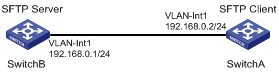
Networking and Configuration Requirements
As shown inFigure 1-15, establish an SSH connection between the SFTP client (Switch A) and the SFTP server (Switch B). Log in to Switch B with the username client001 and password abc through Switch A to manage and transfer files.
Applicable Product Matrix
|
Product series |
Software version |
Hardware version |
|
S5600 series |
Release 1510 |
All versions |
|
S3600-SI/EI series |
Release 1510 |
All versions |
|
S3100-C-SI series S3100-T-SI series |
Release 0011 |
All versions |
|
S3100-52P |
Release 1500 |
S3100-52P |
Configuration Procedure
l Configure the SFTP server (Switch B)
# Generate an RSA key pair.
<SwitchB>system-view
[SwitchB] rsa local-key-pair create
# Create a VLAN interface on the switch and assign an IP address for it. The SSH client will use this address as the destination for SSH connection.
[SwitchB] interface vlan-interface 1
[SwitchB-Vlan-interface1] ip address 192.168.0.1 255.255.255.0
[SwitchB-Vlan-interface1] quit
# Set the authentication mode for the user interfaces to AAA.
[SwitchB] user-interface vty 0 4
[SwitchB-ui-vty0-4] authentication-mode scheme
# Enable the user interfaces to support SSH.
[SwitchB-ui-vty0-4] protocol inbound ssh
[SwitchB-ui-vty0-4] quit
# Create a local user named client001.
[SwitchB] local-user client001
[SwitchB-luser-client001] password simple abc
[SwitchB-luser-client001] service-type ssh
[SwitchB-luser-client001] quit
# Configure the authentication method as password.
[SwitchB] ssh user client001 authentication-type password
# Specify the service type as SFTP.
[SwitchB] ssh user client001 service-type sftp
# Enable the SFTP server.
[SwitchB] sftp server enable
l Configure the SFTP client (Switch A)
# Create a VLAN interface on the switch and assign an IP address for it. This address must be in the same segment with the IP address of the VLAN interface on switch B. In this example, configure it as 192.168.0.2.
<SwitchA> system-view
[SwitchA] interface vlan-interface 1
[SwitchA-Vlan-interface1] ip address 192.168.0.2 255.255.255.0
[SwitchA-Vlan-interface1] quit
# Connect to the remote SFTP server using the username client001 and password abc to enter SFTP client view.
[SwitchA] sftp 192.168.0.1
Input Username: client001
Trying 192.168.0.1 ...
Press CTRL+K to abort
Connected to 192.168.0.1 ...
The Server is not authenticated. Do you continue access it? [Y/N]:y
Do you want to save the server's public key? [Y/N]:n
Enter password:
sftp-client>
# Display the current directory of the server, delete the file z and verify the deletion.
sftp-client> dir
-rwxrwxrwx 1 noone nogroup 1759 Aug 23 06:52 config.cfg
-rwxrwxrwx 1 noone nogroup 225 Aug 24 08:01 pubkey2
-rwxrwxrwx 1 noone nogroup 283 Aug 24 07:39 pubkey1
drwxrwxrwx 1 noone nogroup 0 Sep 01 06:22 new
-rwxrwxrwx 1 noone nogroup 225 Sep 01 06:55 pub
-rwxrwxrwx 1 noone nogroup 0 Sep 01 08:00 z
sftp-client> delete z
The following files will be deleted:
flash:/z
Are you sure to delete it?(Y/N):y
This operation may take a long time.Please wait...
File successfully Removed
sftp-client> dir
-rwxrwxrwx 1 noone nogroup 1759 Aug 23 06:52 config.cfg
-rwxrwxrwx 1 noone nogroup 225 Aug 24 08:01 pubkey2
-rwxrwxrwx 1 noone nogroup 283 Aug 24 07:39 pubkey1
drwxrwxrwx 1 noone nogroup 0 Sep 01 06:22 new
-rwxrwxrwx 1 noone nogroup 225 Sep 01 06:55 pub
# Add a directory named new1, and then check that the new directory has been successfully created.
sftp-client> mkdir new1
New directory created
sftp-client> dir
-rwxrwxrwx 1 noone nogroup 1759 Aug 23 06:52 config.cfg
-rwxrwxrwx 1 noone nogroup 225 Aug 24 08:01 pubkey2
-rwxrwxrwx 1 noone nogroup 283 Aug 24 07:39 pubkey1
drwxrwxrwx 1 noone nogroup 0 Sep 01 06:22 new
-rwxrwxrwx 1 noone nogroup 225 Sep 01 06:55 pub
drwxrwxrwx 1 noone nogroup 0 Sep 02 06:30 new1
# Rename the directory to new2, and then verify the operation.
sftp-client> rename new1 new2
File successfully renamed
sftp-client> dir
-rwxrwxrwx 1 noone nogroup 1759 Aug 23 06:52 config.cfg
-rwxrwxrwx 1 noone nogroup 225 Aug 24 08:01 pubkey2
-rwxrwxrwx 1 noone nogroup 283 Aug 24 07:39 pubkey1
drwxrwxrwx 1 noone nogroup 0 Sep 01 06:22 new
-rwxrwxrwx 1 noone nogroup 225 Sep 01 06:55 pub
drwxrwxrwx 1 noone nogroup 0 Sep 02 06:33 new2
# Download the file pubkey2 from the server, renaming it to public.
sftp-client> get pubkey2 public
This operation may take a long time, please wait...
Remote file:flash:/pubkey2 ---> Local file: public..
Downloading file successfully ended
# Upload file pu to the server and rename it to puk, and then verify the operation.
sftp-client> put pu puk
This operation may take a long time, please wait...
Local file: pu ---> Remote file: flash:/puk
Uploading file successfully ended
sftp-client> dir
-rwxrwxrwx 1 noone nogroup 1759 Aug 23 06:52 config.cfg
-rwxrwxrwx 1 noone nogroup 225 Aug 24 08:01 pubkey2
-rwxrwxrwx 1 noone nogroup 283 Aug 24 07:39 pubkey1
drwxrwxrwx 1 noone nogroup 0 Sep 01 06:22 new
drwxrwxrwx 1 noone nogroup 0 Sep 02 06:33 new2
-rwxrwxrwx 1 noone nogroup 283 Sep 02 06:35 pub
-rwxrwxrwx 1 noone nogroup 283 Sep 02 06:36 puk
sftp-client>
# Exit SFTP.
sftp-client> quit
Bye
Complete Configuration
l Configure Switch B
#
local-user client001
password simple abc
service-type ssh
#
interface Vlan-interface1
ip address 192.168.0.1 255.255.255.0
#
sftp server enable
ssh user client001 authentication-type password
ssh user client001 service-type sftp
#
user-interface vty 0 4
authentication-mode scheme
user privilege level 3
protocol inbound ssh
#
l Configure Switch A
#
interface Vlan-interface1
ip address 192.168.0.2 255.255.255.0
Precautions
None
When Switch Acts as Server for Password Authentication
Network Diagram
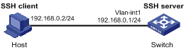
Figure 1-16 Switch acts as server for password authentication
Networking and Configuration Requirements
As shown in Figure 1-16, establish an SSH connection between the host (SSH Client) and the switch (SSH Server) for secure data exchange. The host runs SSH2.0 client software. Password authentication is required.
Applicable Product Matrix
|
Product series |
Software version |
Hardware version |
|
S5600 series |
Release 1602 |
All versions |
|
S5100-SI/EI series |
Release 2200, Release 2201 |
All versions |
|
S3600-SI/EI series |
Release 1602 |
All versions |
|
S3100-EI series |
Release 2104, Release 2107 |
All versions |
|
S3100-C-SI series S3100-T-SI series |
Release 2102, Release 2107 |
All versions |
|
S3100-52P |
Release 1602 |
S3100-52P |
Configuration Procedure
l Configure the SSH server
# Create a VLAN interface on the switch and assign an IP address, which the SSH client will use as the destination for SSH connection.
<Switch> system-view
[Switch] interface vlan-interface 1
[Switch-Vlan-interface1] ip address 192.168.0.1 255.255.255.0
[Switch-Vlan-interface1] quit
![]()
Generating the RSA and DSA key pairs on the server is prerequisite to SSH login.
# Generate RSA and DSA key pairs.
[Switch] public-key local create rsa
[Switch] public-key local create dsa
# Set the authentication mode for the user interfaces to AAA.
[Switch] user-interface vty 0 4
[Switch-ui-vty0-4] authentication-mode scheme
# Enable the user interfaces to support SSH.
[Switch-ui-vty0-4] protocol inbound ssh
[Switch-ui-vty0-4] quit
# Create local client client001, and set the authentication password to abc, protocol type to SSH, and command privilege level to 3 for the client.
[Switch] local-user client001
[Switch-luser-client001] password simple abc
[Switch-luser-client001] service-type ssh level 3
[Switch-luser-client001] quit
# Specify the authentication method of user client001 as password.
[Switch] ssh user client001 authentication-type password
l Configure the SSH client
# Configure an IP address (192.168.0.2 in this case) for the SSH client. This IP address and that of the VLAN interface on the switch must be in the same network segment.
# Configure the SSH client software to establish a connection to the SSH server.
Take SSH client software Putty (version 0.58) as an example:
1) Run PuTTY.exe to enter the following configuration interface.
Figure 1-17 SSH client configuration interface
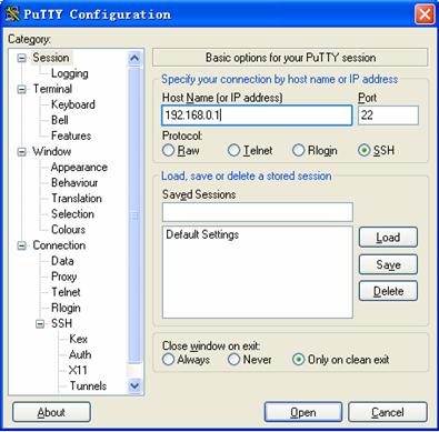
In the Host Name (or IP address) text box, enter the IP address of the SSH server.
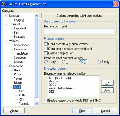
2) From the category on the left pane of the window, select SSH under Connection. The window as shown in Figure 1-18 appears.
Figure 1-18 SSH client configuration interface 2
Under Protocol options, select 2 from Preferred SSH protocol version.
3) As shown in Figure 1-18, click Open. If the connection is normal, you will be prompted to enter the user name client001 and password abc. Once authentication succeeds, you will log in to the server.
Complete Configuration
#
local-user client001
password simple abc
service-type ssh
level 3
#
vlan 1
#
interface Vlan-interface1
ip address 192.168.0.1 255.255.255.0
#
#
ssh user client001 authentication-type password
ssh user client001 service-type stelnet
#
user-interface vty 0 4
authentication-mode scheme
protocol inbound ssh
#
Precautions
l Generating the RSA and DSA key pairs on the server is prerequisite to SSH login.
l After configuring the user interfaces to support SSH, be sure to configure the user interfaces to use AAA authentication by using the authentication-mode scheme command and configure the default domain to use the AAA method of local.
When Switch Acts as Server for Publickey Authentication
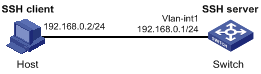
Network Diagram
Figure 1-19 Switch acts as server for publickey authentication
Networking and Configuration Requirements
As shown in Figure 1-19, establish an SSH connection between the host (SSH client) and the switch (SSH Server) for secure data exchange. The host runs SSH2.0 client software. Publickey authentication is required.
Applicable Product Matrix
|
Product series |
Software version |
Hardware version |
|
S5600 series |
Release 1602 |
All versions |
|
S5100-SI/EI series |
Release 2200, Release 2201 |
All versions |
|
S3600-SI/EI series |
Release 1602 |
All versions |
|
S3100-EI series |
Release 2104, Release 2107 |
All versions |
|
S3100-C-SI series S3100-T-SI series |
Release 2102, Release 2107 |
All versions |
|
S3100-52P |
Release 1602 |
S3100-52P |
Configuration Procedure
![]()
Under the publickey authentication mode, either the RSA or DSA public key can be generated for the server to authenticate the client. Here takes the RSA public key as an example.
l Configure the SSH server
# Create a VLAN interface on the switch and assign an IP address, which the SSH client will use as the destination for SSH connection.
<Switch> system-view
[Switch] interface vlan-interface 1
[Switch-Vlan-interface1] ip address 192.168.0.1 255.255.255.0
[Switch-Vlan-interface1] quit
![]()
Generating the RSA and DSA key pairs on the server is prerequisite to SSH login.
# Generate RSA and DSA key pairs.
[Switch] public-key local create rsa
[Switch] public-key local create dsa
# Set the authentication mode for the user interfaces to AAA.
[Switch] user-interface vty 0 4
[Switch-ui-vty0-4] authentication-mode scheme
# Enable the user interfaces to support SSH.
[Switch-ui-vty0-4] protocol inbound ssh
# Set the client’s command privilege level to 3
[Switch-ui-vty0-4] user privilege level 3
[Switch-ui-vty0-4] quit
# Configure the authentication type of the SSH client named client 001 as publickey.
[Switch] ssh user client001 authentication-type publickey
![]()
Before performing the following steps, you must generate an RSA public key pair (using the client software) on the client, save the key pair in a file named public, and then upload the file to the SSH server through FTP or TFTP. For details, refer to Configuring the SSH Client.
# Import the client’s public key named Switch001 from file public.
[Switch] public-key peer Switch001 import sshkey public
# Assign the public key Switch001 to client client001.
[Switch] ssh user client001 assign publickey Switch001
l Configure the SSH client (taking PuTTY version 0.58 as an example)
# Generate an RSA key pair.
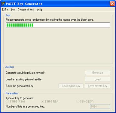
1) Run PuTTYGen.exe, choose SSH2(RSA) and click Generate.
Figure 1-20 Generate a client key pair (1)
![]()
While generating the key pair, you must move the mouse continuously and keep the mouse off the green process bar shown in Figure 1-21. Otherwise, the process bar stops moving and the key pair generating process is stopped.
Figure 1-21 Generate a client key pair (2)
After the key pair is generated, click Save public key and enter the name of the file for saving the public key (public in this case).
Figure 1-22 Generate a client key pair (3)
Likewise, to save the private key, click Save private key. A warning window pops up to prompt you whether to save the private key without any protection. Click Yes and enter the name of the file for saving the private key (private.ppk in this case).
Figure 1-23 Generate a client key pair (4)

![]()
After a public key pair is generated, you need to upload the pubic key file to the server through FTP or TFTP, and complete the server end configuration before you continue to configure the client.
# Establish a connection with the SSH server
2) Launch PuTTY.exe to enter the following interface.
Figure 1-24 SSH client configuration interface 1
In the Host Name (or IP address) text box, enter the IP address of the server.
3) From the category on the left pane of the window, select SSH under Connection. The window as shown in Figure 1-25 appears.
Figure 1-25 SSH client configuration interface 2
Under Protocol options, select 2 from Preferred SSH protocol version.
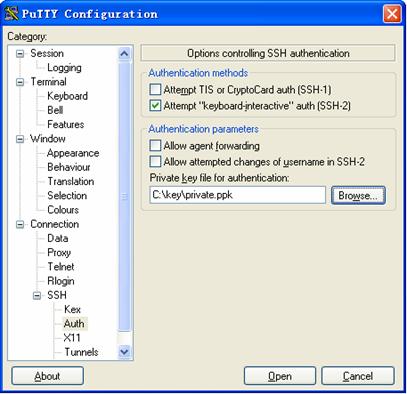
4) Select Connection/SSH/Auth. The following window appears.
Figure 1-26 SSH client configuration interface (2)
Click Browse… to bring up the file selection window, navigate to the private key file and click OK.
5) From the window shown in Figure 1-26, click Open. If the connection is normal, you will be prompted to enter the username.
Complete Configuration
#
public-key peer Switch001
public-key-code begin
30819F300D06092A864886F70D010101050003818D0030818902818100C3FDC7D2ACE733EE
40D78590C4710251119F86F3007EBC818EB5186E040B34582FC02ECD0276CE430F10DC3DDB
4D36332DB9845490C6F00921C2C4C8A15CEFDE45EB82A987E71C529696D1473F2F3FCDED1D
9D3EA7C8B0C05CD188A2DE36C4A627DA798F62D19837A33D5CC9EAEB78CC17CFD6E6B42DD1
public-key-code end
peer-public-key end
#
interface Vlan-interface1
ip address 192.168.0.1 255.255.255.0
#
ssh user client001 assign publickey Switch001
ssh user client001 authentication-type publickey
ssh user client001 service-type stelnet
#
user-interface vty 0 4
authentication-mode scheme
user privilege level 3
protocol inbound ssh
Precautions
Generating the RSA and DSA key pairs on the server is prerequisite to SSH login.
When Switch Acts as Client for Password Authentication
Network Diagram
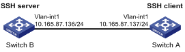
Figure 1-27 Switch acts as client for password authentication
Networking and Configuration Requirements
As shown in Figure 1-27, establish an SSH connection between Switch A (SSH Client) and Switch B (SSH Server) for secure data exchange. The user name for login is client001 and the SSH server’s IP address is 10.165.87.136. Password authentication is required.
Applicable Product Matrix
|
Product series |
Software version |
Hardware version |
|
S5600 series |
Release 1602 |
All versions |
|
S5100-SI/EI series |
Release 2200, Release 2201 |
All versions |
|
S3600-SI/EI series |
Release1602 |
All versions |
|
S3100-EI series |
Release 2104, Release 2107 |
All versions |
|
S3100-C-SI series S3100-T-SI series |
Release 2102, Release 2107 |
All versions |
|
S3100-52P |
Release 1602 |
S3100-52P |
Configuration Procedure
l Configure Switch B
# Create a VLAN interface on the switch and assign an IP address, which the SSH client will use as the destination for SSH connection.
<SwitchB> system-view
[SwitchB] interface vlan-interface 1
[SwitchB-Vlan-interface1] ip address 10.165.87.136 255.255.255.0
[SwitchB-Vlan-interface1] quit
![]()
Generating the RSA and DSA key pairs on the server is prerequisite to SSH login.
# Generate RSA and DSA key pairs.
[SwitchB] public-key local create rsa
[SwitchB] public-key local create dsa
# Set the authentication mode for the user interfaces to AAA.
[SwitchB] user-interface vty 0 4
[SwitchB-ui-vty0-4] authentication-mode scheme
# Enable the user interfaces to support SSH.
[SwitchB-ui-vty0-4] protocol inbound ssh
[SwitchB-ui-vty0-4] quit
# Create local user client001, and set the authentication password to abc, the login protocol to SSH, and user command privilege level to 3.
[SwitchB] local-user client001
[SwitchB-luser-client001] password simple abc
[SwitchB-luser-client001] service-type ssh level 3
[SwitchB-luser-client001] quit
# Configure the authentication type of user client001 as password.
[SwitchB] ssh user client001 authentication-type password
l Configure Switch A
# Create a VLAN interface on the switch and assign an IP address, which serves as the SSH client’s address in an SSH connection.
<SwitchA> system-view
[SwitchA] interface vlan-interface 1
[SwitchA-Vlan-interface1] ip address 10.165.87.137 255.255.255.0
[SwitchA-Vlan-interface1] quit
# Establish a connection to the server 10.165.87.136.
[SwitchA] ssh2 10.165.87.136
Username: client001
Trying 10.165.87.136 ...
Press CTRL+K to abort
Connected to 10.165.87.136 ...
The Server is not authenticated. Do you continue to access it?(Y/N):y
Do you want to save the server's public key?(Y/N):n
Enter password:
**************************************************************************
* Copyright(c) 2004-2007 Hangzhou H3C Tech. Co., Ltd. All rights reserved.*
* Without the owner's prior written consent, *
* no decompiling or reverse-engineering shall be allowed. *
**************************************************************************
<SwitchB>
Complete Configuration
l Configure Switch B
#
local-user client001
password simple abc
service-type ssh
level 3
#
interface Vlan-interface1
ip address 10.165.87.136 255.255.255.0
#
ssh user client001 authentication-type password
ssh user client001 service-type stelnet
#
user-interface vty 0 4
authentication-mode scheme
protocol inbound ssh
l Configure Switch A
#
interface Vlan-interface1
ip address 10.165.87.137 255.255.255.0
#
Precautions
l Generating the RSA and DSA key pairs on the server is prerequisite to SSH login.
l After configuring the user interfaces to support SSH, be sure to configure the user interfaces to use AAA authentication by using the authentication-mode scheme command and configure the default domain to use the AAA method of local.
When Switch Acts as Client for Publickey Authentication
Network Diagram
Figure 1-28 Switch acts as client for publickey authentication
Networking and Configuration Requirements
As shown in Figure 1-28, establish an SSH connection between Switch A (SSH Client) and Switch B (SSH Server) for secure data exchange. The user name is client001 and the SSH server’s IP address is 10.165.87.136. Publickey authentication is required.
Applicable Product Matrix
|
Product series |
Software version |
Hardware version |
|
S5600 series |
Release 1602 |
All versions |
|
S5100-SI/EI series |
Release 2200, Release 2201 |
All versions |
|
S3600-SI/EI series |
Release 1602 |
All versions |
|
S3100-EI series |
Release 2104, Release 2107 |
All versions |
|
S3100-C-SI series S3100-T-SI series |
Release 2102, Release 2107 |
All versions |
|
S3100-52P |
Release 1602 |
S3100-52P |
Configuration Procedure
![]()
In public key authentication, you can use either RSA or DSA public key. Here takes the DSA public key as an example.
l Configure Switch B
# Create a VLAN interface on the switch and assign an IP address, which the SSH client will use as the destination for SSH connection.
<SwitchB> system-view
[SwitchB] interface vlan-interface 1
[SwitchB-Vlan-interface1] ip address 10.165.87.136 255.255.255.0
[SwitchB-Vlan-interface1] quit
![]()
Generating the RSA and DSA key pairs on the server is prerequisite to SSH login.
# Generate RSA and DSA key pairs.
[SwitchB] public-key local create rsa
[SwitchB] public-key local create dsa
# Set the authentication mode for the user interfaces to AAA.
[SwitchB] user-interface vty 0 4
[SwitchB-ui-vty0-4] authentication-mode scheme
# Enable the user interfaces to support SSH.
[SwitchB-ui-vty0-4] protocol inbound ssh
# Set the user command privilege level to 3.
[SwitchB-ui-vty0-4] user privilege level 3
[SwitchB-ui-vty0-4] quit
# Specify the authentication type of user client001 as publickey.
[SwitchB] ssh user client001 authentication-type publickey
![]()
Before doing the following steps, you must first generate a DSA public key pair on the client and save the key pair in a file named Switch001, and then upload the file to the SSH server through FTP or TFTP. For details, refer to “Configure Switch A”.
# Import the client public key pair named Switch001 from the file Switch001.
[SwitchB] public-key peer Switch001 import sshkey Switch001
# Assign the public key Switch001 to user client001.
[SwitchB] ssh user client001 assign publickey Switch001
l Configure Switch A
# Create a VLAN interface on the switch and assign an IP address, which serves as the SSH client’s address in an SSH connection.
<SwitchA> system-view
[SwitchA] interface vlan-interface 1
[SwitchA-Vlan-interface1] ip address 10.165.87.137 255.255.255.0
[SwitchA-Vlan-interface1] quit
# Generate a DSA key pair
[SwitchA] public-key local create dsa
# Export the generated DSA key pair to a file named Switch001.
[SwitchA] public-key local export dsa ssh2 Switch001
![]()
After the key pair is generated, you need to upload the pubic key file to the server through FTP or TFTP and complete the server end configuration before you continue to configure the client.
# Establish an SSH connection to the server 10.165.87.136.
[SwitchA] ssh2 10.165.87.136 identity-key dsa
Username: client001
Trying 10.165.87.136 ...
Press CTRL+K to abort
Connected to 10.165.87.136 ...
The Server is not authenticated. Do you continue to access it?(Y/N):y
Do you want to save the server's public key?(Y/N):n
**************************************************************************
* Copyright(c) 2004-2007 Hangzhou H3C Tech. Co., Ltd. All rights reserved.*
* Without the owner's prior written consent, *
* no decompiling or reverse-engineering shall be allowed. *
**************************************************************************
<SwitchB>
Complete Configuration
l Configure Switch B
#
public-key peer Switch001
public-key-code begin
308201B73082012C06072A8648CE3804013082011F02818100D757262C4584C44C211F18BD
96E5F061C4F0A423F7FE6B6B85B34CEF72CE14A0D3A5222FE08CECE65BE6C265854889DC1E
DBD13EC8B274DA9F75BA26CCB987723602787E922BA84421F22C3C89CB9B06FD60FE01941D
DD77FE6B12893DA76EEBC1D128D97F0678D7722B5341C8506F358214B16A2FAC4B36895038
7811C7DA33021500C773218C737EC8EE993B4F2DED30F48EDACE915F0281810082269009E1
4EC474BAF2932E69D3B1F18517AD9594184CCDFCEAE96EC4D5EF93133E84B47093C52B20CD
35D02492B3959EC6499625BC4FA5082E22C5B374E16DD00132CE71B020217091AC717B6123
91C76C1FB2E88317C1BD8171D41ECB83E210C03CC9B32E810561C21621C73D6DAAC028F4B1
585DA7F42519718CC9B09EEF0381840002818066E34E6F395E111C559A97BCB67B019DAA4C
4292E4AF541F71DD16A4CE6463F55491B38B24E5F7DC7CFD0B80F6E61916C60DB29DC62B44
AFC87ED3725AB6592BE5F2D3BA64BC1ACC5642D493C64A915157514D0C94A0019BBB38E7B8
092765BB30FB45C78C2B7EF564BF8F0C27E9A923675DCCEEAC193413BD120D43652A149E
public-key-code end
peer-public-key end
#
interface Vlan-interface1
ip address 10.165.87.136 255.255.255.0
#
ssh user client001 assign publickey Switch001
ssh user client001 authentication-type publickey
ssh user client001 service-type stelnet
#
user-interface vty 0 4
authentication-mode scheme
user privilege level 3
protocol inbound ssh
l Configure Switch A
#
interface Vlan-interface1
ip address 10.165.87.137 255.255.255.0
#
Precautions
Generating the RSA and DSA key pairs on the server is prerequisite to SSH login.
When Switch Acts as Client and First-Time Authentication is not Supported
Network Diagram
Figure 1-29 Switch acts as client and first-time authentication is not supported
Networking and Configuration Requirements
As shown in Figure 1-29, establish an SSH connection between Switch A (SSH Client) and Switch B (SSH Server) for secure data exchange. The user name is client001 and the SSH server’s IP address is 10.165.87.136. The publickey authentication mode is used to enhance security.
Applicable Product Matrix
|
Product series |
Software version |
Hardware version |
|
S5600 series |
Release 1602 |
All versions |
|
S5100-SI/EI series |
Release 2200, Release 2201 |
All versions |
|
S3600-SI/EI series |
Release 1602 |
All versions |
|
S3100-EI series |
Release 2104, Release 2107 |
All versions |
|
S3100-C-SI series S3100-T-SI series |
Release 2102, Release 2107 |
All versions |
|
S3100-52P |
Release 1602 |
S3100-52P |
Configuration Procedure
l Configure Switch B
# Create a VLAN interface on the switch and assign an IP address for it to serve as the destination of the client.
<SwitchB> system-view
[SwitchB] interface vlan-interface 1
[SwitchB-Vlan-interface1] ip address 10.165.87.136 255.255.255.0
[SwitchB-Vlan-interface1] quit
![]()
Generating the RSA and DSA key pairs on the server is prerequisite to SSH login.
# Generate RSA and DSA key pairs.
[SwitchB] public-key local create rsa
[SwitchB] public-key local create dsa
# Set AAA authentication on user interfaces.
[SwitchB] user-interface vty 0 4
[SwitchB-ui-vty0-4] authentication-mode scheme
# Configure the user interfaces to support SSH.
[SwitchB-ui-vty0-4] protocol inbound ssh
# Set the user command privilege level to 3.
[SwitchB-ui-vty0-4] user privilege level 3
[SwitchB-ui-vty0-4] quit
# Specify the authentication type for user client001 as publickey.
[SwitchB] ssh user client001 authentication-type publickey
![]()
Before doing the following steps, you must first generate a DSA key pair on the client and save the key pair in a file named Switch001, and then upload the file to the SSH server through FTP or TFTP. For details, refer to the following “Configure Switch A”.
# Import the client’s public key file Switch001 and name the public key as Switch001.
[SwitchB] public-key peer Switch001 import sshkey Switch001
# Assign public key Switch001 to user client001
[SwitchB] ssh user client001 assign publickey Switch001
# Export the generated DSA host public key pair to a file named Switch002.
[SwitchB] public-key local export dsa ssh2 Switch002
![]()
When first-time authentication is not supported, you must first generate a DSA key pair on the server and save the key pair in a file named Switch002, and then upload the file to the SSH client through FTP or TFTP.
l Configure Switch A
# Create a VLAN interface on the switch and assign an IP address, which serves as the SSH client’s address in an SSH connection.
<SwitchA> system-view
[SwitchA] interface vlan-interface 1
[SwitchA-Vlan-interface1] ip address 10.165.87.137 255.255.255.0
[SwitchA-Vlan-interface1] quit
# Generate a DSA key pair
[SwitchA] public-key local create dsa
# Export the generated DSA key pair to a file named Switch001.
[SwitchA] public-key local export dsa ssh2 Switch001
![]()
After generating the key pair, you need to upload the key pair file to the server through FTP or TFTP and complete the server end configuration before you continue to configure the client.
# Disable first-time authentication on the device.
[SwitchA] undo ssh client first-time
![]()
When first-time authentication is not supported, you must first generate a DSA key pair on the server and save the key pair in a file named Switch002, and then upload the file to the SSH client through FTP or TFTP. For details, refer to the above part “Configure Switch B”.
# Import the public key pair named Switch002 from the file Switch002.
[SwitchA] public-key peer Switch002 import sshkey Switch002
# Specify the host public key pair name of the server.
[SwitchA] ssh client 10.165.87.136 assign publickey Switch002
# Establish the SSH connection to server 10.165.87.136.
[SwitchA] ssh2 10.165.87.136 identity-key dsa
Username: client001
Trying 10.165.87.136 ...
Press CTRL+K to abort
Connected to 10.165.87.136 ...
**************************************************************************
* Copyright(c) 2004-2007 Hangzhou H3C Tech. Co., Ltd. All rights reserved.*
* Without the owner's prior written consent, *
* no decompiling or reverse-engineering shall be allowed. *
**************************************************************************
<SwitchB>
Complete Configuration
l Configure Switch B
#
public-key peer Switch001
public-key-code begin
308201B73082012C06072A8648CE3804013082011F02818100D757262C4584C44C211F18BD
96E5F061C4F0A423F7FE6B6B85B34CEF72CE14A0D3A5222FE08CECE65BE6C265854889DC1E
DBD13EC8B274DA9F75BA26CCB987723602787E922BA84421F22C3C89CB9B06FD60FE01941D
DD77FE6B12893DA76EEBC1D128D97F0678D7722B5341C8506F358214B16A2FAC4B36895038
7811C7DA33021500C773218C737EC8EE993B4F2DED30F48EDACE915F0281810082269009E1
4EC474BAF2932E69D3B1F18517AD9594184CCDFCEAE96EC4D5EF93133E84B47093C52B20CD
35D02492B3959EC6499625BC4FA5082E22C5B374E16DD00132CE71B020217091AC717B6123
91C76C1FB2E88317C1BD8171D41ECB83E210C03CC9B32E810561C21621C73D6DAAC028F4B1
585DA7F42519718CC9B09EEF0381840002818066E34E6F395E111C559A97BCB67B019DAA4C
4292E4AF541F71DD16A4CE6463F55491B38B24E5F7DC7CFD0B80F6E61916C60DB29DC62B44
AFC87ED3725AB6592BE5F2D3BA64BC1ACC5642D493C64A915157514D0C94A0019BBB38E7B8
092765BB30FB45C78C2B7EF564BF8F0C27E9A923675DCCEEAC193413BD120D43652A149E
public-key-code end
peer-public-key end
#
vlan 1
#
interface Vlan-interface1
ip address 10.165.87.136 255.255.255.0
#
ssh user client001 assign publickey Switch001
ssh user client001 authentication-type publickey
ssh user client001 service-type stelnet
#
user-interface vty 0 4
authentication-mode scheme
user privilege level 3
protocol inbound ssh
#
l Configure Switch A
#
public-key peer Switch002
public-key-code begin
308201B83082012C06072A8648CE3804013082011F02818100D757262C4584C44C211F18BD
96E5F061C4F0A423F7FE6B6B85B34CEF72CE14A0D3A5222FE08CECE65BE6C265854889DC1E
DBD13EC8B274DA9F75BA26CCB987723602787E922BA84421F22C3C89CB9B06FD60FE01941D
DD77FE6B12893DA76EEBC1D128D97F0678D7722B5341C8506F358214B16A2FAC4B36895038
7811C7DA33021500C773218C737EC8EE993B4F2DED30F48EDACE915F0281810082269009E1
4EC474BAF2932E69D3B1F18517AD9594184CCDFCEAE96EC4D5EF93133E84B47093C52B20CD
35D02492B3959EC6499625BC4FA5082E22C5B374E16DD00132CE71B020217091AC717B6123
91C76C1FB2E88317C1BD8171D41ECB83E210C03CC9B32E810561C21621C73D6DAAC028F4B1
585DA7F42519718CC9B09EEF0381850002818100A777C1A45FCF8F3B267944D7AF6F8F24FA
9301B452E833710EE0A076A44ED6B70D114E9CDFE58BF4081D347D1664376D33C365C07200
9ACC6347BACA0C0D6AB8D4954861458CFB5EE469155FD649CC406640FCECCD663036E0A1C2
73D56A04C56ED5B240F9C6C1C680CF97A7A04381A340EC94B28C73C71541D89880778C2D94
public-key-code end
peer-public-key end
#
vlan 1
#
interface Vlan-interface1
ip address 10.165.87.137 255.255.255.0
#
undo ssh client first-time
ssh client 10.165.87.136 assign publickey Switch002
#
Precautions
Generating the RSA and DSA key pairs on the server is prerequisite to SSH login.
SFTP Configuration
Network Diagram
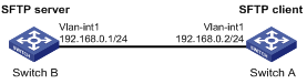
Figure 1-30 Network diagram for SFTP configuration
Networking and Configuration Requirements
As shown in Figure 1-30, establish an SSH connection between the SFTP client (switch A) and the SFTP server (switch B). Log in to switch B through switch A to manage and transmit files. An SFTP user with the username client001 and password abc exists on the SFTP server.
Applicable Product Matrix
|
Product series |
Software version |
Hardware version |
|
S5600 series |
Release 1602 |
All versions |
|
S5100-SI/EI series |
Release 2200, Release 2201 |
All versions |
|
S3600-SI/EI series |
Release 1602 |
All versions |
|
S3100-EI series |
Release 2104, Release 2107 |
All versions |
|
S3100-C-SI series S3100-T-SI series |
Release 2102, Release 2107 |
All versions |
|
S3100-52P |
Release 1602 |
S3100-52P |
Configuration Procedure
1) Configure the SFTP server (switch B)
# Create key pairs.
<SwitchB> system-view
[SwitchB] public-key local create rsa
[SwitchB] public-key local create dsa
# Create a VLAN interface on the switch and assign to it an IP address, which is used as the destination address for the client to connect to the SFTP server.
[SwitchB] interface vlan-interface 1
[SwitchB-Vlan-interface1] ip address 192.168.0.1 255.255.255.0
[SwitchB-Vlan-interface1] quit
# Specify the SSH authentication mode as AAA.
[SwitchB] user-interface vty 0 4
[SwitchB-ui-vty0-4] authentication-mode scheme
# Configure the protocol through which the remote user logs in to the switch as SSH.
[SwitchB-ui-vty0-4] protocol inbound ssh
[SwitchB-ui-vty0-4] quit
# Create a local user client001.
[SwitchB] local-user client001
[SwitchB-luser-client001] password simple abc
[SwitchB-luser-client001] service-type ssh
[SwitchB-luser-client001] quit
# Configure the authentication mode as password. Authentication timeout time, retry number, and update time of the server key adopt the default values.
[SwitchB] ssh user client001 authentication-type password
# Specify the service type as SFTP.
[SwitchB] ssh user client001 service-type sftp
# Enable the SFTP server.
[SwitchB] sftp server enable
2) Configure the SFTP client (switch A)
# Configure the IP address of the VLAN interface on switch A. It must be in the same segment with the IP address of the VLAN interface on switch B. In this example, configure it as 192.168.0.2.
<SwitchA> system-view
[SwitchA] interface vlan-interface 1
[SwitchA-Vlan-interface1] ip address 192.168.0.2 255.255.255.0
[SwitchA-Vlan-interface1] quit
# Connect to the remote SFTP server. Enter the username client001 and the password abc, and then enter SFTP client view.
[SwitchA] sftp 192.168.0.1
Input Username: client001
Trying 192.168.0.1 ...
Press CTRL+K to abort
Connected to 192.168.0.1 ...
The Server is not authenticated. Do you continue to access it?(Y/N):y
Do you want to save the server's public key?(Y/N):n
Enter password:
sftp-client>
# Display the current directory of the server. Delete the file z and verify the result.
sftp-client> dir
-rwxrwxrwx 1 noone nogroup 1759 Aug 23 06:52 config.cfg
-rwxrwxrwx 1 noone nogroup 225 Aug 24 08:01 pubkey2
-rwxrwxrwx 1 noone nogroup 283 Aug 24 07:39 pubkey1
drwxrwxrwx 1 noone nogroup 0 Sep 01 06:22 new
-rwxrwxrwx 1 noone nogroup 225 Sep 01 06:55 pub
-rwxrwxrwx 1 noone nogroup 0 Sep 01 08:00 z
Received status: End of file
Received status: Success
sftp-client> delete z
The following files will be deleted:
/z
Are you sure to delete it?(Y/N):y
This operation may take a long time.Please wait...
Received status: Success
File successfully Removed
sftp-client> dir
-rwxrwxrwx 1 noone nogroup 1759 Aug 23 06:52 config.cfg
-rwxrwxrwx 1 noone nogroup 225 Aug 24 08:01 pubkey2
-rwxrwxrwx 1 noone nogroup 283 Aug 24 07:39 pubkey1
drwxrwxrwx 1 noone nogroup 0 Sep 01 06:22 new
-rwxrwxrwx 1 noone nogroup 225 Sep 01 06:55 pub
Received status: End of file
Received status: Success
# Add a directory new1, and then check whether the new directory is successfully created.
sftp-client> mkdir new1
Received status: Success
New directory created
sftp-client> dir
-rwxrwxrwx 1 noone nogroup 1759 Aug 23 06:52 config.cfg
-rwxrwxrwx 1 noone nogroup 225 Aug 24 08:01 pubkey2
-rwxrwxrwx 1 noone nogroup 283 Aug 24 07:39 pubkey1
drwxrwxrwx 1 noone nogroup 0 Sep 01 06:22 new
-rwxrwxrwx 1 noone nogroup 225 Sep 01 06:55 pub
drwxrwxrwx 1 noone nogroup 0 Sep 02 06:30 new1
Received status: End of file
Received status: Success
# Rename the directory new1 as new2, and then verify the result.
sftp-client> rename new1 new2
File successfully renamed
sftp-client> dir
-rwxrwxrwx 1 noone nogroup 1759 Aug 23 06:52 config.cfg
-rwxrwxrwx 1 noone nogroup 225 Aug 24 08:01 pubkey2
-rwxrwxrwx 1 noone nogroup 283 Aug 24 07:39 pubkey1
drwxrwxrwx 1 noone nogroup 0 Sep 01 06:22 new
-rwxrwxrwx 1 noone nogroup 225 Sep 01 06:55 pub
drwxrwxrwx 1 noone nogroup 0 Sep 02 06:33 new2
Received status: End of file
Received status: Success
# Download the file pubkey2 from the server and rename it as public.
sftp-client> get pubkey2 public
This operation may take a long time, please wait...
.
Remote file:/pubkey2 ---> Local file: public..
Received status: End of file
Received status: Success
Downloading file successfully ended
# Upload file pu to the server and rename it as puk, and then verify the result.
sftp-client> put pu puk
This operation may take a long time, please wait...
Local file: pu ---> Remote file: /puk
Received status: Success
Uploading file successfully ended
sftp-client> dir
-rwxrwxrwx 1 noone nogroup 1759 Aug 23 06:52 config.cfg
-rwxrwxrwx 1 noone nogroup 225 Aug 24 08:01 pubkey2
-rwxrwxrwx 1 noone nogroup 283 Aug 24 07:39 pubkey1
drwxrwxrwx 1 noone nogroup 0 Sep 01 06:22 new
drwxrwxrwx 1 noone nogroup 0 Sep 02 06:33 new2
-rwxrwxrwx 1 noone nogroup 283 Sep 02 06:35 pub
-rwxrwxrwx 1 noone nogroup 283 Sep 02 06:36 puk
Received status: End of file
Received status: Success
sftp-client>
# Exit SFTP.
sftp-client> quit
Bye
[Sysname]
Complete Configuration
l Configure Switch B
#
local-user client001
password simple abc
service-type ssh
#
vlan 1
#
interface Vlan-interface1
ip address 192.168.0.1 255.255.255.0
#
sftp server enable
ssh user client001 authentication-type password
ssh user client001 service-type sftp
#
user-interface vty 0 4
authentication-mode scheme
protocol inbound ssh
#
l Configure Switch A
#
vlan 1
#
interface Vlan-interface1
ip address 192.168.0.2 255.255.255.0
#
Precautions
Generating the RSA and DSA key pairs on the server is prerequisite to SSH login.