- Table of Contents
-
- H3C Low-End Ethernet Switches Configuration Guide(V1.01)
- 01-Login Configuration Guide
- 02-VLAN Configuration Guide
- 03-IP Address Configuration Guide
- 04-Voice VLAN Configuration Guide
- 05-GVRP Configuration Guide
- 06-Ethernet Interface Basic Configuration Guide
- 07-Link Aggregation Configuration Guide
- 08-Port Isolation Configuration Guide
- 09-Port Security Configuration Guide
- 10-Port Binding Configuration Guide
- 11-MAC Address Table Management Configuration Guide
- 12-DLDP Configuration Guide
- 13-Auto Detect Configuration Guide
- 14-MSTP Configuration Guide
- 15-Routing Configuration Guide
- 16-Multicast Configuration Guide
- 17-802.1x Configuration Guide
- 18-AAA Configuration Guide
- 19-MAC Authentication Configuration Guide
- 20-VRRP Configuration Guide
- 21-ARP Configuration Guide
- 22-DHCP Configuration Guide
- 23-ACL Configuration Guide
- 24-QoS-QoS Profile Configuration Guide
- 25-Web Cache Redirection Configuration Guide
- 26-Mirroring Configuration Guide
- 27-IRF Configuration Guide
- 28-Cluster Configuration Guide
- 29-PoE-PoE Profile Configuration Guide
- 30-UDP Helper Configuration Guide
- 31-SNMP-RMON Configuration Guide
- 32-NTP Configuration Guide
- 33-SSH Configuration Guide
- 34-FTP and TFTP Configuration Guide
- 35-Information Center Configuration Guide
- 36-VLAN-VPN Configuration Guide
- 37-HWPing Configuration Guide
- 38-DNS Configuration Guide
- 39-Access Management Configuration Guide
- 40-Web Authentication Configuration Guide
- 41-IPv6 Management Configuration Guide
- 42-Smart link - Monitor Link Configuration Guide
- 43-VLAN Mapping Configuration Guide
- Related Documents
-
| Title | Size | Download |
|---|---|---|
| 02-VLAN Configuration Guide | 67.98 KB |
Networking and Configuration Requirements
Configuring Protocol-Based VLAN·
Networking and Configuration Requirements
Configuring Port-Based VLAN
Network Diagram
Figure 1-1 Network diagram for port-based VLAN configuration

Networking and Configuration Requirements
In the sample intranet network shown in Figure 1-1, Switch A is connected to the subnet of a department and the subnet for the public servers, and Switch B is connected to the subnet of the other two departments.
To guarantee data security for each department, use VLANs to isolate the four subnets at Layer 2 but configure Layer-3 interfaces on Switch A to enable the hosts of the three departments and the public servers to communicate with each other at Layer 3.
Applicable Product Matrix
|
Product series |
Software version |
Hardware version |
|
S5600 series |
Release 1510, Release1602 |
All versions |
|
S5100-SI/EI series |
Release 2200, Release2201 |
All versions |
|
S3600-SI/EI series |
Release 1510, Release1602 |
All versions |
|
S3100-EI series |
Release 2104, Release 2107 |
All versions |
|
S3100-C-SI series S3100-T-SI series |
Release 0011, Release 2102, Release 2107 |
All versions |
|
S3100-52P |
Release 1500, Release 1602 |
S3100-52P |
![]()
The S3600-SI/EI series and S5600 series switches can operate as Switch A in Figure 1-1 for forwarding packets at Layer 3 for VLANs. The other models in the table above do not support configuring multiple VLAN interfaces for Layer-3 forwarding, and therefore, they can operate as only Switch B for Layer-2 isolation with VLANs, as shown in Figure 1-1.
Configuration Procedure
l Configure Switch A
# Create VLAN 10 on Switch A and assign Ethernet 1/0/1 to VLAN 10.
[SwitchA] vlan 10
[SwitchA-vlan10] port Ethernet 1/0/1
[SwitchA-vlan10] quit
# Create VLAN 100 on Switch A and assign Ethernet 1/0/2 to VLAN 100.
[SwitchA] vlan 100
[SwitchA-vlan100] port Ethernet 1/0/2
[SwitchA-vlan100] quit
# Create VLAN 101 and VLAN 102 on Switch A.
[SwitchA] vlan 101 to 102
# Create VLAN-interface 10, VLAN-interface 100, VLAN-interface 101, and VLAN-interface 102, and configure an IP address for each of these VLAN-interfaces.
[SwitchA] interface Vlan-interface 10
[SwitchA-Vlan-interface10] ip address 192.168.10.1 24
[SwitchA-Vlan-interface10] quit
[SwitchA] interface Vlan-interface 100
[SwitchA-Vlan-interface100] ip address 192.168.100.1 24
[SwitchA-Vlan-interface100] quit
[SwitchA] interface Vlan-interface 101
[SwitchA-Vlan-interface101] ip address 192.168.101.1 24
[SwitchA-Vlan-interface101] quit
[SwitchA] interface Vlan-interface 102
[SwitchA-Vlan-interface102] ip address 192.168.102.1 24
[SwitchA-Vlan-interface102] quit
# Configure Ethernet 1/0/3 of Switch A to be a trunk port and to permit the packets carrying the tag of VLAN 101 or VLAN 102 to pass through.
[SwitchA] interface Ethernet 1/0/3
[SwitchA-Ethernet1/0/3] port link-type trunk
[SwitchA-Ethernet1/0/3] port trunk permit vlan 101 102
l Configure Switch B
# Create VLAN 101 on Switch B, and assign Ethernet 1/0/11 to VLAN 101.
[SwitchB] vlan 101
[SwitchB-vlan101] port Ethernet 1/0/11
[SwitchB-vlan101] quit
# Create VLAN 102 on Switch B, and assign Ethernet 1/0/12 to VLAN 102.
[SwitchB] vlan 102
[SwitchB-vlan102] port Ethernet 1/0/12
[SwitchB-vlan102] quit
# Configure Ethernet 1/0/10 of Switch B to be a trunk port and to permit the packets carrying the tag of VLAN 101 or VLAN 102 to pass through.
[SwitchB] interface Ethernet 1/0/10
[SwitchB-Ethernet1/0/10] port link-type trunk
[SwitchB-Ethernet1/0/10] port trunk permit vlan 101 102
Complete Configuration
l Configuration on Switch A
#
vlan 10
#
vlan 100
#
vlan 101
#
vlan 102
#
interface Vlan-interface 10
ip address 192.168.10.1 255.255.255.0
#
interface Vlan-interface 100
ip address 192.168.100.1 255.255.255.0
#
interface Vlan-interface 101
ip address 192.168.101.1 255.255.255.0
#
interface Vlan-interface 102
ip address 192.168.102.1 255.255.255.0
#
interface Ethernet1/0/1
port access vlan 10
#
interface Ethernet1/0/2
port access vlan 100
#
interface Ethernet1/0/3
port link-type trunk
port trunk permit vlan 1 101 102
l Configuration on Switch B
#
vlan 101
#
vlan 102
#
interface Ethernet1/0/10
port link-type trunk
port trunk permit vlan 1 101 102
#
interface Ethernet1/0/11
port access vlan 101
#
interface Ethernet1/0/12
port access vlan 201
Precautions
l After you assign the servers and the workstations to different VLANs, they cannot communicate with each other. For them to communicate, you need to configure a Layer 3 VLAN interface for each of them on the switches.
l After you telnet to an Ethernet port on a switch to make configuration, do not remove the port from its current VLAN. Otherwise, your Telnet connection will be disconnected.
Configuring Protocol-Based VLAN
Network Diagram
Figure 1-2 Network diagram for protocol-based VLAN configuration
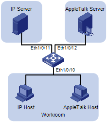
Networking and Configuration Requirements
Applicable Product Matrix
|
Product series |
Software version |
Hardware version |
|
S5600 series |
Release 1510, Release1602 |
All versions |
|
S5100-SI/EI series |
Release 2200, Release2201 |
All versions |
|
S3600-SI/EI series |
Release 1510, Release1602 |
All versions |
|
S3100-EI series |
Release 2104, Release 2107 |
All versions |
|
S3100-52P |
Release 1500, Release 1602 |
S3100-52P |
Configuration Procedure
# Create VLAN 100 and assign Ethernet1/0/11 to VLAN 100.
[H3C] vlan 100
[H3C-vlan100] port Ethernet 1/0/11
# Create VLAN 200 and assign Ethernet 1/0/12 to VLAN 200.
[H3C-vlan100] quit
[H3C] vlan 200
[H3C-vlan200] port Ethernet 1/0/12
# Configure protocol templates and bind them to ports.
Create a protocol template for VLAN 200 to carry Appletalk and a protocol template for VLAN 100 to carry IP.
[H3C-vlan200] protocol-vlan at
[H3C-vlan200] quit
[H3C] vlan 100
[H3C-vlan100] protocol-vlan ip
Create a user-defined protocol template for VLAN 100 to carry ARP for IP communication, assuming that Ethernet_II encapsulation is used.
[H3C-vlan100] protocol-vlan mode ethernetii etype 0806
Configure Ethernet 1/0/10 to be a hybrid port and to remove the outer VLAN tag when forwarding packets of VLAN 100 and VLAN 200.
[H3C-vlan100] quit
[H3C] interface Ethernet 1/0/10
[H3C-Ethernet1/0/10] port link-type hybrid
[H3C-Ethernet1/0/10] port hybrid vlan 100 200 untagged
Bind Ethernet 1/0/10 to protocol template 0 and protocol template 1 of VLAN 100, and protocol template 0 of VLAN 200.
![]()
When configuring a protocol template, you can assign a number to the template. If you fail to do that, the system automatically assigns the lowest available number to the template. Thus, in this configuration example, the two protocol templates for VLAN 100 are automatically numbered 0 and 1, and the protocol template for VLAN 200 is numbered 0.
[H3C-Ethernet1/0/10] port hybrid protocol-vlan vlan 100 0 to 1
[H3C-Ethernet1/0/10] port hybrid protocol-vlan vlan 200 0
Complete Configuration
#
vlan 100
protocol-vlan 0 ip
protocol-vlan 1 mode ethernetii etype 0806
#
vlan 200
protocol-vlan 0 at
#
interface Ethernet1/0/10
port link-type hybrid
port hybrid vlan 1 100 200 untagged
port hybrid protocol-vlan vlan 100 0
port hybrid protocol-vlan vlan 100 1
port hybrid protocol-vlan vlan 200 0
#
interface Ethernet1/0/11
port access vlan 100
#
interface Ethernet1/0/12
port access vlan 200
Precautions
l At present, the S3100 series support only the standard templates of AppleTalk and IP, the standard template of IPX encapsulated in Ethernet II format, and the user-defined templates matching the Ethernet II encapsulation format. Protocol templates matching 802.2/802.3 encapsulation formats and their extended encapsulation formats are not supported on the S3100 series currently.
l Because IP depends on ARP for address resolution in Ethernet, you are recommended to configure the IP and ARP templates in the same VLAN and associate them with the same port to prevent communication failure.