- Table of Contents
-
- H3C Low-End Ethernet Switches Configuration Guide(V1.01)
- 01-Login Configuration Guide
- 02-VLAN Configuration Guide
- 03-IP Address Configuration Guide
- 04-Voice VLAN Configuration Guide
- 05-GVRP Configuration Guide
- 06-Ethernet Interface Basic Configuration Guide
- 07-Link Aggregation Configuration Guide
- 08-Port Isolation Configuration Guide
- 09-Port Security Configuration Guide
- 10-Port Binding Configuration Guide
- 11-MAC Address Table Management Configuration Guide
- 12-DLDP Configuration Guide
- 13-Auto Detect Configuration Guide
- 14-MSTP Configuration Guide
- 15-Routing Configuration Guide
- 16-Multicast Configuration Guide
- 17-802.1x Configuration Guide
- 18-AAA Configuration Guide
- 19-MAC Authentication Configuration Guide
- 20-VRRP Configuration Guide
- 21-ARP Configuration Guide
- 22-DHCP Configuration Guide
- 23-ACL Configuration Guide
- 24-QoS-QoS Profile Configuration Guide
- 25-Web Cache Redirection Configuration Guide
- 26-Mirroring Configuration Guide
- 27-IRF Configuration Guide
- 28-Cluster Configuration Guide
- 29-PoE-PoE Profile Configuration Guide
- 30-UDP Helper Configuration Guide
- 31-SNMP-RMON Configuration Guide
- 32-NTP Configuration Guide
- 33-SSH Configuration Guide
- 34-FTP and TFTP Configuration Guide
- 35-Information Center Configuration Guide
- 36-VLAN-VPN Configuration Guide
- 37-HWPing Configuration Guide
- 38-DNS Configuration Guide
- 39-Access Management Configuration Guide
- 40-Web Authentication Configuration Guide
- 41-IPv6 Management Configuration Guide
- 42-Smart link - Monitor Link Configuration Guide
- 43-VLAN Mapping Configuration Guide
- Related Documents
-
| Title | Size | Download |
|---|---|---|
| 20-VRRP Configuration Guide | 119.65 KB |
Single VRRP Group Configuration
Networking and Configuration Requirements
Multiple VRRP Groups Configuration
Networking and Configuration Requirements
Networking and Configuration Requirements
Networking and Configuration Requirements
1 VRRP Configuring Guide
Single VRRP Group Configuration
Virtual Router Redundancy Protocol (VRRP) is an error-tolerant protocol defined in RFC 2338. In LANs with multicast or broadcast capabilities (such as Ethernet), VRRP can avoid single point failure through establishing backup links without modifying the configuration of dynamic routing protocols and router discovery protocols.
Network Diagram
Figure 1-1 Network diagram for VRRP
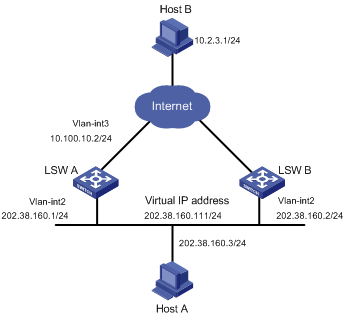
Networking and Configuration Requirements
Host A accesses Host B on the Internet, with the VRRP group consisting of Switch A and Switch B as its default gateway.
VRRP group settings:
l VRRP group number: 1
l Virtual router IP address of the VRRP group: 202.38.160.111/24.
l Switch A acts as the master.
l Switch B acts as the backup, and works in the preemptive mode.
Table 1-1 Networking description
|
Switch |
Ethernet port connected with Host A |
IP address of the VLAN interface |
Switch priority in the VRRP group |
Working mode |
|
LSW-A |
Ethernet 1/0/6 |
202.38.160.1/24 |
110 |
Preemptive mode |
|
LSW-B |
Ethernet 1/0/5 |
202.38.160.2/24 |
100 (default) |
Preemptive mode |
Applicable Product Matrix
|
Product series |
Software version |
Hardware version |
|
S5600 series |
Release 1510, Release1602 |
All versions |
|
S3600-EI series |
Release 1510, Release1602 |
All versions |
Configuration Procedure
1) Configure Switch A.
# Configure VLAN 2.
<LSW-A> system-view
[LSW-A] vlan 2
[LSW-A-vlan2] port Ethernet1/0/6
[LSW-A-vlan2] quit
[LSW-A] interface Vlan-interface 2
[LSW-A-Vlan-interface2] ip address 202.38.160.1 255.255.255.0
[LSW-A-Vlan-interface2] quit
# Enable a VRRP group to respond to ping operations destined for its virtual IP address.
[LSW-A] vrrp ping-enable
# Create a VRRP group.
[LSW-A] interface Vlan-interface 2
[LSW-A-Vlan-interface2] vrrp vrid 1 virtual-ip 202.38.160.111
# Set the priority of Switch A in the VRRP group to 110.
[LSW-A-Vlan-interface2] vrrp vrid 1 priority 110
# Configure preemptive mode for the VRRP group.
[LSW-A-Vlan-interface2] vrrp vrid 1 preempt-mode
![]()
By default, a VRRP group adopts the preemptive mode.
2) Configure Switch B.
# Configure VLAN 2.
<LSW-B> system-view
[LSW-B] vlan 2
[LSW-B-Vlan2] port Ethernet1/0/5
[LSW-B-vlan2] quit
[LSW-B] interface Vlan-interface 2
[LSW-B-Vlan-interface2] ip address 202.38.160.2 255.255.255.0
[LSW-B-Vlan-interface2] quit
# Enable the VRRP group to respond to ping operations destined for its virtual IP address.
[LSW-B] vrrp ping-enable
# Create a VRRP group.
[LSW-B] interface vlan 2
[LSW-B-Vlan-interface2] vrrp vrid 1 virtual-ip 202.38.160.111
# Configure preemptive mode for the VRRP group.
[LSW-B-Vlan-interface2] vrrp vrid 1 preempt-mode
The default gateway of Host A is configured as 202.38.160.111.
Normally, Switch A functions as the gateway. When Switch A is turned off or fails, Switch B functions as the gateway.
Complete Configuration
l Configurations on Switch A
#
vrrp ping-enable
#
interface Vlan-interface1
ip address 202.38.160.1 255.255.255.0
vrrp vrid 1 virtual-ip 202.38.160.111
vrrp vrid 1 priority 110
#
interface Ethernet1/0/6
port access vlan 2
#
l Configurations on Switch B
#
vrrp ping-enable
#
interface Vlan-interface1
ip address 202.38.160.2 255.255.255.0
vrrp vrid 1 virtual-ip 202.38.160.111
#
interface Ethernet1/0/5
port access vlan 2
#
Precautions
l For the IP address owner, its priority in the VRRP group is always 255.
l Do not configure multiple VRRP groups on the same VLAN interface. Otherwise, the VRRP function will be affected.
l If both switches in the preemptive mode and switches in the non-preemptive mode exist in a VRRP group, the working mode of the VRRP group conforms to that of the master. For example, if the master works in the preemptive mode, when the master fails, the VRRP group will elect a new master through preemption although there are switches working in the non-preemptive mode.
Multiple VRRP Groups Configuration
Network Diagram
Figure 1-2 Network diagram for VRRP
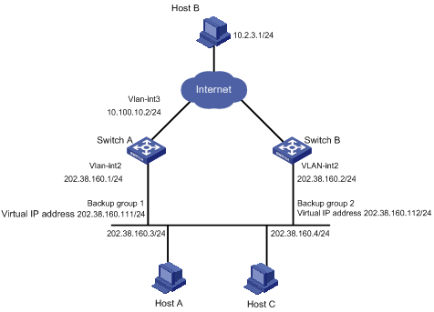
Networking and Configuration Requirements
A switch can backup multiple VRRP groups.
Applicable Product Matrix
|
Product series |
Software version |
Hardware version |
|
S5600 series |
Release 1510, Release1602 |
All versions |
|
S3600-EI series |
Release 1510, Release1602 |
All versions |
Configuration Procedure
l Configure Switch A.
# Configure VLAN 2.
<LSW-A> system-view
[LSW-A] vlan 2
[LSW-A-vlan2] port Ethernet1/0/6
[LSW-A-vlan2] quit
[LSW-A] interface Vlan-interface 2
[LSW-A-Vlan-interface2] ip address 202.38.160.1 255.255.255.0
# Create VRRP group 1.
[LSW-A-Vlan-interface2] vrrp vrid 1 virtual-ip 202.38.160.111
# Set the priority of Switch A in VRRP group 1 to 150.
[LSW-A-Vlan-interface2] vrrp vrid 1 priority 150
# Create VRRP group 2.
[LSW-A-Vlan-interface2] vrrp vrid 2 virtual-ip 202.38.160.112
l Configure Switch B.
# Configure VLAN 2.
<LSW-B> system-view
[LSW-B] vlan 2
[LSW-B-vlan2] port Ethernet1/0/6
[LSW-B-vlan2] quit
[LSW-B] interface Vlan-interface 2
[LSW-B-Vlan-interface2] ip address 202.38.160.2 255.255.255.0
# Create VRRP group 1.
[LSW-B-Vlan-interface2] vrrp vrid 1 virtual-ip 202.38.160.111
# Create VRRP group 2.
[LSW-B-Vlan-interface2] vrrp vrid 2 virtual-ip 202.38.160.112
# Set the priority of Switch B in VRRP group 2 to 110.
[LSW-B-Vlan-interface2] vrrp vrid 2 priority 110
Complete Configuration
l Configurations on Switch A
#
interface Vlan-interface2
ip address 202.38.160.1 255.255.255.0
vrrp vrid 1 virtual-ip 202.38.160.111
vrrp vrid 1 priority 150
vrrp vrid 2 virtual-ip 202.38.160.112
#
interface Ethernet1/0/6
port access vlan 2
#
l Configurations on Switch B
#
interface Vlan-interface2
ip address 202.38.160.2 255.255.255.0
vrrp vrid 1 virtual-ip 202.38.160.111
vrrp vrid 2 virtual-ip 202.38.160.112
vrrp vrid 2 priority 110
#
interface Ethernet1/0/6
port access vlan 2
#
Precautions
l For the IP address owner, its priority in the VRRP group is always 255.
l Multiple-VRRP group configuration is commonly used in real networking, for multiple VRRP groups can implement load sharing.
l Do not configure multiple VRRP groups on the same VLAN interface. Otherwise, the VRRP function will be affected.
l If both switches in the preemptive mode and switches in the non-preemptive mode exist in a VRRP group, the working mode of the VRRP group conforms to that of the master. For example, if the master works in the preemptive mode, when it fails, the VRRP group will elect a new master through preemption although there are switches working in the non-preemptive mode.
VRRP Interface Tracking
VRRP interface tracking extends the backup functionality of a backup in a VRRP group. With this function enabled, a backup can backup the master not only when the VRRP group resident interface fails, but also when other interfaces of the master become unavailable. This is achieved by tracking an interface of a master.
Network Diagram
Figure 1-3 Network diagram for VRRP
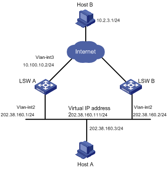
Networking and Configuration Requirements
Switch A is the master and Switch B is the backup in a VRRP group. Both Switch A and Switch B have an interface connected with the Internet. Configure the VRRP interface tracking function, so that when the interface connected with the Internet on Switch A becomes unavailable, Switch B can replace Switch A to act as the gateway even if Switch A is still working.
Applicable Product Matrix
|
Product series |
Software version |
Hardware version |
|
S5600 series |
Release 1510, Release1602 |
All versions |
|
S3600-EI series |
Release 1510, Release1602 |
All versions |
Configuration Procedure
l Configure Switch A.
# Configure VLAN 2.
<LSW-A> system-view
[LSW-A] vlan 2
[LSW-A-vlan2] port Ethernet1/0/6
[LSW-A-vlan2] quit
[LSW-A] interface Vlan-interface 2
[LSW-A-Vlan-interface2] ip address 202.38.160.1 255.255.255.0
[LSW-A-Vlan-interface2] quit
# Enable the VRRP group to respond to ping operations destined for its virtual IP address.
[LSW-A] vrrp ping-enable
# Create VRRP group 1.
[LSW-A] interface Vlan-interface 2
[LSW-A-Vlan-interface2] vrrp vrid 1 virtual-ip 202.38.160.111
# Set the priority of Switch A in VRRP group 1 to 110.
[LSW-A-Vlan-interface2] vrrp vrid 1 priority 110
# Set the interface to be tracked.
[LSW-A-Vlan-interface2] vrrp vrid 1 track interface Vlan-interface 3 reduced 30
l Configure Switch B.
# Configure VLAN 2.
<LSW-B> system-view
[LSW-B] vlan 2
[LSW-B-vlan2] port Ethernet1/0/5
[LSW-B-vlan2] quit
[LSW-B] interface Vlan-interface 2
[LSW-B-Vlan-interface2] ip address 202.38.160.2 255.255.255.0
[LSW-B-Vlan-interface2] quit
# Enable a VRRP group to respond to ping operations destined for its virtual IP address.
[LSW-B] vrrp ping-enable
# Create VRRP group 1.
[LSW-B] interface Vlan-interface 2
[LSW-B-Vlan-interface2] vrrp vrid 1 virtual-ip 202.38.160.111
When VLAN-interface 3 resumes to work, Switch A becomes the master again to act as the gateway.
Complete Configuration
l Configuration on Switch A
#
vrrp ping-enable
#
interface Vlan-interface2
ip address 202.38.160.1 255.255.255.0
vrrp vrid 1 virtual-ip 202.38.160.111
vrrp vrid 1 priority 110
vrrp vrid 1 track Vlan-interface1 reduced 30
#
interface Ethernet1/0/6
port access vlan 2
#
l Configurations on Switch B
#
vrrp ping-enable
#
interface Vlan-interface2
ip address 202.38.160.2 255.255.255.0
vrrp vrid 1 virtual-ip 202.38.160.111
#
interface Ethernet1/0/5
port access vlan 2
#
Precautions
l For the IP address owner, its priority in the VRRP group is always 255.
l When configuring VRRP interface tracking, you are recommended to configure the uplink Trunk port to deny the VLAN that corresponds to the tracked interface.
l When you set the priority decrease value of the master in a VRRP group, make sure that the master has a lower priority than the backups after the decrease.
VRRP Port Tracking
VRRP group port tracking function can track the link state of a physical port, and decrease the priority of the switch when the physical port fails.
Network Diagram
Figure 1-4 Network diagram for VRRP port tracking
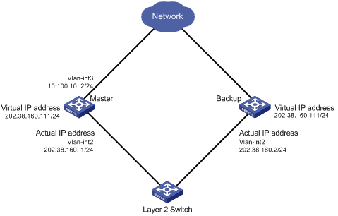
Networking and Configuration Requirements
l There are two switches, the master and the backup, in VRRP group 1.
l The IP addresses of the master and the backup are 202.38.160.1 and 202.38.160.2 respectively.
l The master is connected with the upstream network through port Ethernet 1/0/1 that belongs to VLAN 3, and is connected with a Layer 2 switch through Ethernet 1/0/2 that belongs to VLAN 2.
l The virtual IP address of the VRRP group is 202.38.160.111.
Applicable Product Matrix
|
Software version |
Hardware version |
|
|
S5600 series |
Release 1510, Release1602 |
All versions |
|
S3600-EI series |
Release 1510, Release1602 |
All versions |
Configuration Procedure
![]()
On the backup, the configurations related to the upstream and downstream device connection, and the configurations related to the VRRP group have been finished. The configuration procedures are omitted here.
Perform the following configurations on the master:
# Configure VLAN 3.
<Sysname> system-view
[Sysname] vlan 3
[Sysname-vlan3] port Ethernet1/0/1
[Sysname-vlan3] quit
[Sysname] interface Vlan-interface 3
[Sysname-Vlan-interface3] ip address 10.100.10.2 255.255.255.0
[Sysname-Vlan-interface3] quit
# Configure VLAN 2.
[Sysname] vlan 2
[Sysname-vlan2] port Ethernet1/0/2
[Sysname-vlan2] quit
[Sysname] interface Vlan-interface 2
[Sysname-Vlan-interface2] ip address 202.38.160.1 255.255.255.0
[Sysname-Vlan-interface2] quit
# Create VRRP group 1.
[Sysname] interface Vlan-interface 2
[Sysname-Vlan-interface2] vrrp vrid 1 virtual-ip 202.38.160.111
[Sysname-Vlan-interface2] quit
# Enter port view of Ethernet 1/0/1 and enable the VRRP port tracking function.
[Sysname] interface Ethernet1/0/1
[Sysname-Ethernet1/0/1] vrrp Vlan-interface 2 vrid 1 track reduced 50
Complete Configuration
On the master:
#
interface Vlan-interface2
ip address 202.38.160.1 255.255.255.0
vrrp vrid 1 virtual-ip 202.38.160.111
#
interface Vlan-interface3
ip address 10.100.10.2 255.255.255.0
#
interface Ethernet1/0/1
port access vlan 3
vrrp Vlan-interface 2 vrid 1 track reduced 50
#
interface Ethernet1/0/2
port access vlan 2
#
Precautions
l For the IP address owner, its priority in the VRRP group is always 255.
l When you set the priority decrease value of the master in a VRRP group, make sure that the master has a lower priority than the backups after the decrease.