- Table of Contents
-
- H3C Low-End Ethernet Switches Configuration Guide(V1.01)
- 01-Login Configuration Guide
- 02-VLAN Configuration Guide
- 03-IP Address Configuration Guide
- 04-Voice VLAN Configuration Guide
- 05-GVRP Configuration Guide
- 06-Ethernet Interface Basic Configuration Guide
- 07-Link Aggregation Configuration Guide
- 08-Port Isolation Configuration Guide
- 09-Port Security Configuration Guide
- 10-Port Binding Configuration Guide
- 11-MAC Address Table Management Configuration Guide
- 12-DLDP Configuration Guide
- 13-Auto Detect Configuration Guide
- 14-MSTP Configuration Guide
- 15-Routing Configuration Guide
- 16-Multicast Configuration Guide
- 17-802.1x Configuration Guide
- 18-AAA Configuration Guide
- 19-MAC Authentication Configuration Guide
- 20-VRRP Configuration Guide
- 21-ARP Configuration Guide
- 22-DHCP Configuration Guide
- 23-ACL Configuration Guide
- 24-QoS-QoS Profile Configuration Guide
- 25-Web Cache Redirection Configuration Guide
- 26-Mirroring Configuration Guide
- 27-IRF Configuration Guide
- 28-Cluster Configuration Guide
- 29-PoE-PoE Profile Configuration Guide
- 30-UDP Helper Configuration Guide
- 31-SNMP-RMON Configuration Guide
- 32-NTP Configuration Guide
- 33-SSH Configuration Guide
- 34-FTP and TFTP Configuration Guide
- 35-Information Center Configuration Guide
- 36-VLAN-VPN Configuration Guide
- 37-HWPing Configuration Guide
- 38-DNS Configuration Guide
- 39-Access Management Configuration Guide
- 40-Web Authentication Configuration Guide
- 41-IPv6 Management Configuration Guide
- 42-Smart link - Monitor Link Configuration Guide
- 43-VLAN Mapping Configuration Guide
- Related Documents
-
| Title | Size | Download |
|---|---|---|
| 15-Routing Configuration Guide | 441.19 KB |
Networking and Configuration Requirements
Networking and Configuration Requirements
Networking and Configuration Requirements
Networking and Configuration Requirements
Configuring a (Totally) Stub Area·
Networking and Configuration Requirements
Configuring a (Totally) NSSA Area·
Networking and Configuration Requirements
Configuring OSPF Route Summarization·
Networking and Configuration Requirements
Networking and Configuration Requirements
Configuring BGP Confederation Attribute
Networking and Configuration Requirements
Networking and Configuration Requirements
Configuring BGP Path Selection
Networking and Configuration Requirements
Networking and Configuration Requirements
Configuring Static Routes
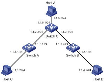
A static route is manually configured by an administrator. In a simple network, you only need to configure static routes to make the network work normally. The proper configuration and usage of static routes can improve network performance and ensure the bandwidth for important applications. However, if a fault occurs to the network, the corresponding static routes cannot be updated dynamically, and the network administrator has to modify the static routes manually.
For two devices to be reachable to each other, you need to configure a static route to the peer on each device.
Network Diagram
Figure 1-1 Network diagram for static route configuration
Networking and Configuration Requirements
A small company has a simple and stable office network. The company’s existing devices that do not support dynamic routing protocols. The company requires that any two nodes on the network can communicate with each other and that the existing devices can be fully utilized.
In this case, static routes can enable communication between any two nodes on the network.
Applicable Product Matrix
|
Product series |
Software version |
Hardware version |
|
S5600 series |
Release 1510, Release 1602 |
All versions |
|
S5100-SI/EI series |
Release 2200, Release 2201 |
All versions |
|
S3600-SI/EI series |
Release 1510, Release 1602 |
All versions |
|
S3100-EI series |
Release 2104, Release 2107 |
All versions |
|
S3100-C-SI series S3100-T-SI series |
Release 0011, Release 2102, Release 2107 |
All versions |
|
S3100-52P |
Release 1500, Release 1602 |
S3100-52P |
Configuration Procedure
Configure the switches:
l Configure static routes on Switch A.
<SwitchA> system-view
[SwitchA] ip route-static 1.1.3.0 255.255.255.0 1.1.2.2
[SwitchA] ip route-static 1.1.4.0 255.255.255.0 1.1.2.2
[SwitchA] ip route-static 1.1.5.0 255.255.255.0 1.1.2.2
l Configure static routes on Switch B.
<SwitchB> system-view
[SwitchB] ip route-static 1.1.2.0 255.255.255.0 1.1.3.1
[SwitchB] ip route-static 1.1.5.0 255.255.255.0 1.1.3.1
[SwitchB] ip route-static 1.1.1.0 255.255.255.0 1.1.3.1
l Configure static routes on Switch C.
<SwitchC> system-view
[SwitchC] ip route-static 1.1.1.0 255.255.255.0 1.1.2.1
[SwitchC] ip route-static 1.1.4.0 255.255.255.0 1.1.3.2
Configure the hosts:
# Configure the default gateway of Host A as 1.1.5.1. Detailed configuration procedure is omitted.
# Configure the default gateway of Host B as 1.1.4.1. Detailed configuration procedure is omitted.
# Configure the default gateway of Host C as 1.1.1.1. Detailed configuration procedure is omitted.
Complete Configuration
l Perform the following configuration on Switch A.
#
ip route-static 1.1.3.0 255.255.255.0 1.1.2.2 preference 60
ip route-static 1.1.4.0 255.255.255.0 1.1.2.2 preference 60
ip route-static 1.1.5.0 255.255.255.0 1.1.2.2 preference 60
l Perform the following configuration on Switch B.
#
ip route-static 1.1.2.0 255.255.255.0 1.1.3.1 preference 60
ip route-static 1.1.5.0 255.255.255.0 1.1.3.1 preference 60
ip route-static 1.1.1.0 255.255.255.0 1.1.3.1 preference 60
l Perform the following configuration on Switch C.
#
ip route-static 1.1.1.0 255.255.255.0 1.1.2.1 preference 60
ip route-static 1.1.4.0 255.255.255.0 1.1.3.2 preference 60
Precautions
Note the following when configuring a static route:
l If the nexthop of a static route is indirectly connected, the static route takes effect (that is, it is installed into the routing table) only if a route to the nexthop exists in the routing table.
l You cannot configure the next hop of a static route as the address of an interface on the local switch.
l You can configure different preferences or an identical preference for routes to the same destination for route backup or load sharing.
l The default route has both the destination and mask configured as 0.0.0.0. If the destination IP address of a packet does not match any entry in the routing table, the router will select the default route to forward the packet
Configuring RIP
RIP is a Distance-Vector (D-V) routing protocol. It advertises routing information in User Datagram Protocol (UDP) datagrams.
RIP uses a hop count, or a routing cost, as the metric to a destination. The hop count from a router to a directly connected network is 0, and that to a network which can be reached through another router is 1, and so on. To restrict the convergence time, RIP prescribes that a cost is an integer ranging from 0 and 15. A hop count equal to or exceeding 16 is defined as infinite; that is, the destination network or the host is unreachable. To improve performance and avoid routing loops, RIP supports split horizon. Besides, RIP can redistribute routes from other routing protocols.
Network Diagram
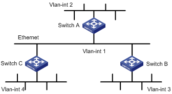
Figure 1-2 Network diagram for RIP configuration
|
Device |
Interface |
IP address |
Device |
Interface |
IP address |
|
Switch A |
Vlan-int1 |
110.11.2.1/24 |
Switch B |
Vlan-int1 |
110.11.2.2/24 |
|
|
Vlan-int2 |
155.10.1.1/24 |
|
Vlan-int3 |
196.38.165.1/24 |
|
Switch C |
Vlan-int1 |
110.11.2.3/24 |
|
|
|
|
|
Vlan-int4 |
117.102.0.1/16 |
|
|
|
Networking and Configuration Requirements
A small company requires a small office network where any two nodes can communicate with each other, and the network devices can automatically adapt to topology changes.
In this case, RIPv2 can enable communication between any two nodes on the network.
Applicable Product Matrix
|
Product series |
Software version |
Hardware version |
|
S3600-SI/EI Series Ethernet switches |
Release 1510, Release1602 |
All versions |
|
S5600 Series Ethernet switches |
Release 1510, Release1602 |
All versions |
Configuration Procedure
l Configure Switch A.
# Configure RIP.
<SwitchA> system-view
[SwitchA] interface Vlan-interface 1
[SwitchA-Vlan-interface1] ip address 110.11.2.1 24
[SwitchA-Vlan-interface1] rip version 2
[SwitchA-Vlan-interface1] quit
[SwitchA] interface Vlan-interface 2
[SwitchA-Vlan-interface2] ip address 155.10.1.1 24
[SwitchA-Vlan-interface2] rip version 2
[SwitchA-Vlan-interface2] quit
[SwitchA] rip
[SwitchA-rip] undo summary
[SwitchA-rip] network 110.11.2.0
[SwitchA-rip] network 155.10.1.0
l Configure Switch B.
# Configure RIP.
<SwitchB> system-view
[SwitchB] interface Vlan-interface 1
[SwitchB-Vlan-interface1] ip address 110.11.2.2 24
[SwitchB-Vlan-interface1] rip version 2
[SwitchB-Vlan-interface1] quit
[SwitchB] interface Vlan-interface 3
[SwitchB-Vlan-interface3] ip address 196.38.165.1 24
[SwitchB-Vlan-interface3] rip version 2
[SwitchB-Vlan-interface3] quit
[SwitchB] rip
[SwitchB-rip] undo summary
[SwitchB-rip] network 196.38.165.0
[SwitchB-rip] network 110.11.2.0
l Configure Switch C.
# Configure RIP.
<SwitchC> system-view
[SwitchC] interface Vlan-interface 1
[SwitchC-Vlan-interface1] ip address 110.11.2.3 24
[SwitchC-Vlan-interface1] rip version 2
[SwitchC-Vlan-interface1] quit
[SwitchC] interface Vlan-interface 4
[SwitchC-Vlan-interface4] ip address 117.102.0.1 16
[SwitchC-Vlan-interface4] rip version 2
[SwitchC-Vlan-interface4] quit
[SwitchC] rip
[SwitchC-rip] undo summary
[SwitchC-rip] network 117.102.0.0
[SwitchC-rip] network 110.11.2.0
Complete Configuration
l Perform the following configuration on Switch A.
#
vlan 1
#
vlan 2
#
interface Vlan-interface1
ip address 110.11.2.1 255.255.255.0
rip version 2 multicast
#
interface Vlan-interface2
ip address 155.10.1.1 255.255.255.0
rip version 2 multicast
#
rip
undo summary
network 110.0.0.0
network 155.10.0.0
#
l Perform the following configuration on Switch B.
#
vlan 1
#
vlan 3
#
interface Vlan-interface1
ip address 110.11.2.2 255.255.255.0
rip version 2 multicast
#
interface Vlan-interface3
ip address 196.38.165.1 255.255.255.0
rip version 2 multicast
#
rip
undo summary
network 196.38.165.0
network 110.0.0.0
l Perform the following configuration on Switch C.
#
vlan 1
#
vlan 4
#
interface Vlan-interface1
ip address 110.11.2.3 255.255.255.0
rip version 2 multicast
#
interface Vlan-interface4
ip address 117.102.0.1 255.255.0.0
rip version 2 multicast
#
rip
undo summary
network 117.0.0.0
network 110.0.0.0
Precautions
l RIPv2 supports automatic route summarization (with the summary command). This function is enabled by default.
l To use RIP updates to advertise subnet routes, disable RIPv2 route automatic summarization.
l Based on your needs, you can configure the switch to receive or send RIP packets with the rip input command or the rip output command.
Configuring OSPF
Open Shortest Path First (OSPF) is a link state interior gateway protocol developed by the IETF. At present, OSPF version 2 (RFC 2328) is used. OSPF has the following features:
l Wide-spread application
l Fast convergence
l Loop-free
l Multicast transmission
l Area partition
l Routing hierarchy
l Authentication
Network Diagram
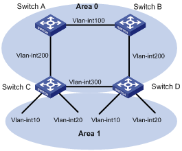
Figure 1-3 Network diagram for OSPF basic configuration
|
Device |
Interface |
IP address |
Router ID |
|
Switch A |
Vlan-int100 |
10.1.1.1/24 |
1.1.1.1 |
|
Vlan-int200 |
10.1.2.1/24 |
||
|
Switch B |
Vlan-int100 |
10.1.1.2/24 |
2.2.2.2 |
|
Vlan-int200 |
10.1.3.1/24 |
||
|
Switch C |
Vlan-int200 |
10.1.2.2/24 |
3.3.3.3 |
|
Vlan-int300 |
10.1.4.1/24 |
||
|
Vlan-int10 |
192.168.1.1/24 |
||
|
Vlan-int20 |
192.168.2.1/24 |
||
|
Switch D |
Vlan-int200 |
10.1.3.2/24 |
4.4.4.4 |
|
Vlan-int300 |
10.1.4.2/24 |
||
|
Vlan-int10 |
192.168.10.1/24 |
||
|
Vlan-int20 |
192.168.20.1/24 |
Networking and Configuration Requirements
In Figure 1-3, Switch A, Switch B, Switch C, and Switch D run OSPF to forward packets. For network security, disable the downlink VLAN interfaces on Switch C and Switch D from sending OSPF packets.
Applicable Product Matrix
|
Product series |
Software version |
Hardware version |
|
S3600-EI Series Ethernet switches |
Release 1510, Release1602 |
All versions |
|
S5600 Series Ethernet switches |
Release 1510, Release1602 |
All versions |
Configuration Procedure
l Configure Switch A.
# Create VLANs and configure IP addresses for VLAN interfaces. The configuration procedure is omitted.
# Configure OSPF.
<SwitchA> system-view
[SwitchA] ospf 1 router-id 1.1.1.1
[SwitchA-ospf-1] area 0
[SwitchA-ospf-1-area-0.0.0.0] network 10.1.1.0 0.0.0.255
[SwitchA-ospf-1-area-0.0.0.0] network 10.1.2.0 0.0.0.255
[SwitchA-ospf-1-area-0.0.0.0] quit
[SwitchA-ospf-1] quit
l Configure Switch B (refer to the configuration on Switch A).
l Configure Switch C.
# Create VLANs and configure IP addresses for VLAN interfaces. The configuration procedure is omitted.
# Configure OSPF.
<SwitchC> system-view
[SwitchC] router id 3.3.3.3
# Disable the interfaces from sending OSPF packets.
[SwitchC] ospf
[SwitchC-ospf-1] silent-interface Vlan-interface 10
[SwitchC-ospf-1] silent-interface Vlan-interface 20
# Enable the interfaces in the specified areas to run OSPF.
[SwitchC-ospf-1] area 0
[SwitchC-ospf-1-area-0.0.0.0] network 10.1.2.0 0.0.0.255
[SwitchC-ospf-1-area-0.0.0.0] network 10.1.4.0 0.0.0.255
[SwitchC-ospf-1-area-0.0.0.0] quit
[SwitchC-ospf-1] area 1
[SwitchC-ospf-1-area-0.0.0.1] network 192.168.1.0 0.0.0.255
[SwitchC-ospf-1-area-0.0.0.1] network 192.168.2.0 0.0.0.255
[SwitchC-ospf-1-area-0.0.0.1] quit
[SwitchC-ospf-1] quit
l Configure Switch D (refer to the configuration on Switch C).
Complete Configuration
l Perform the following configuration on Switch A.
#
vlan 100
#
vlan 200
#
interface Vlan-interface100
ip address 10.1.1.1 255.255.255.0
#
interface Vlan-interface200
ip address 10.1.2.1 255.255.255.0
#
ospf 1 router-id 1.1.1.1
area 0.0.0.0
network 10.1.1.0 0.0.0.255
network 10.1.2.0 0.0.0.255
#
l Perform the following configuration on Switch B.
#
vlan 100
#
vlan 200
#
interface Vlan-interface100
ip address 10.1.1.2 255.255.255.0
#
interface Vlan-interface200
ip address 10.1.3.1 255.255.255.0
#
ospf 1 router-id 2.2.2.2
area 0.0.0.0
network 10.1.1.0 0.0.0.255
network 10.1.3.0 0.0.0.255
#
l Perform the following configuration on Switch C.
#
router id 3.3.3.3
#
vlan 10
#
vlan 20
#
vlan 200
#
vlan 300
#
interface Vlan-interface10
ip address 192.168.1.1 255.255.255.0
#
interface Vlan-interface20
ip address 192.168.2.1 255.255.255.0
#
interface Vlan-interface200
ip address 10.1.2.2 255.255.255.0
#
interface Vlan-interface300
ip address 10.1.4.1 255.255.255.0
#
ospf 1
silent-interface Vlan-interface10
silent-interface Vlan-interface20
area 0.0.0.1
network 192.168.1.0 0.0.0.255
network 192.168.2.0 0.0.0.255
#
area 0.0.0.0
network 10.1.2.0 0.0.0.255
network 10.1.4.0 0.0.0.255
#
l Perform the following configuration on Switch D.
#
router id 4.4.4.4
#
vlan 10
#
vlan 20
#
vlan 200
#
vlan 300
#
interface Vlan-interface10
ip address 192.168.10.1 255.255.255.0
#
interface Vlan-interface20
ip address 192.168.20.1 255.255.255.0
#
interface Vlan-interface200
ip address 10.1.3.2 255.255.255.0
#
interface Vlan-interface300
ip address 10.1.4.2 255.255.255.0
#
ospf 1
silent-interface Vlan-interface10
silent-interface Vlan-interface20
area 0.0.0.1
network 192.168.10.0 0.0.0.255
network 192.168.20.0 0.0.0.255
#
area 0.0.0.0
network 10.1.3.0 0.0.0.255
network 10.1.4.0 0.0.0.255
#
Precautions
l Before configuring OSPF basic functions, configure a router ID for each OSPF process to ensure OSPF runs normally. You are recommended to use the ospf command to configure router IDs for the processes, especially on a device running multiple processes.
Configuring OSPF DR Election
On broadcast or NBMA networks, any two routers need to exchange routing information with each other. If n routers are present on a network, n × (n-1)/2 adjacencies are required. Any route change on a router in such a network generates traffic for routing information synchronization, consuming network resources. The Designated Router (DR) is defined to solve the problem. All the other routers on the network send routing information to the DR, which is responsible for advertising link state information.
On a network, a BDR is elected along with a DR and establishes adjacencies with all the other routers for routing information exchange. When the DR fails, the BDR will become the new DR in a very short period by avoiding adjacency establishment and DR re-election. Meanwhile, other routers elect another BDR, which requires a relatively long period but has no influence on routing calculation.
A router that is neither a DR nor a BDR is a DRother. It forms adjacencies with the DR and BDR, but it neither establishes adjacencies nor exchange routing information with each other, thus reducing the number of adjacencies on broadcast and NBMA networks.
The DR and BDR in a network are elected by all the routers attached to the network. The DR priority of an interface determines its qualification for DR/BDR election. Interfaces attached to the network and having priorities higher than 0 are election candidates. The election votes are hello packets.
Network Diagram
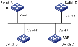
Figure 1-4 Network diagram for DR/BDR election
|
Device |
Interface |
IP address |
Router ID |
Interface priority |
|
Switch A |
Vlan-int1 |
196.1.1.1/24 |
1.1.1.1 |
100 |
|
Switch B |
Vlan-int1 |
196.1.1.2/24 |
2.2.2.2 |
0 |
|
Switch C |
Vlan-int1 |
196.1.1.3/24 |
3.3.3.3 |
2 |
|
Switch D |
Vlan-int1 |
196.1.1.4/24 |
4.4.4.4 |
1 |
Networking and Configuration Requirements
Use OSPF to enable communication between devices in a broadcast network. Devices with higher performance should become the DR and BDR to improve network performance. Disable the devices with lower performance from taking part in the DR/BDR election.
Based on the customer requirements and networking environment, assign proper priorities to interfaces.
Applicable Product Matrix
|
Product series |
Software version |
Hardware version |
|
S3600-EI Series Ethernet switches |
Release 1510, Release1602 |
All versions |
|
S5600 Series Ethernet switches |
Release 1510, Release1602 |
All versions |
Configuration Procedure
l Configure Switch A.
# Assign a router ID to Switch A.
<SwitchA> system-view
[SwitchA] router id 1.1.1.1
# Configure an IP address for the VLAN interface.
[SwitchA] interface Vlan-interface 1
[SwitchA-Vlan-interface1] ip address 196.1.1.1 255.255.255.0
# Assign a DR priority to the VLAN interface.
[SwitchA-Vlan-interface1] ospf dr-priority 100
[SwitchA-Vlan-interface1] quit
# Enable OSPF and specify the VLAN interface to belong to OSPF area 0.
[SwitchA] ospf
[SwitchA-ospf-1] area 0
[SwitchA-ospf-1-area-0.0.0.0] network 196.1.1.0 0.0.0.255
l Configure Switch B.
# Assign a router ID to Switch B.
<SwitchB> system-view
[SwitchB] router id 2.2.2.2
# Configure the IP address of the VLAN interface attached to area 0 and assign DR priority 0 to the interface, so Switch B will not participate in DR/BDR election. Enable OSPF and specify the VLAN interface to belong to area 0.
[SwitchB] interface Vlan-interface 1
[SwitchB-Vlan-interface1] ip address 196.1.1.2 255.255.255.0
[SwitchB-Vlan-interface1] ospf dr-priority 0
[SwitchB-Vlan-interface1] quit
[SwitchB] ospf
[SwitchB-ospf-1] area 0
[SwitchB-ospf-1-area-0.0.0.0] network 196.1.1.0 0.0.0.255
[SwitchB-ospf-1-area-0.0.0.0] quit
[SwitchB-ospf-1] quit
l Configure Switch C.
# Assign a router ID to Switch C.
<SwitchC> system-view
[SwitchC] router id 3.3.3.3
# Configure an IP address for the VLAN interface.
[SwitchC] interface Vlan-interface 1
[SwitchC-Vlan-interface1] ip address 196.1.1.3 255.255.255.0
# Assign a DR priority to the VLAN interface.
[SwitchC-Vlan-interface1] ospf dr-priority 2
[SwitchC-Vlan-interface1] quit
# Enable OSPF and specify the VLAN interface to belong to area 0.
[SwitchC] ospf
[SwitchC-ospf-1] area 0
[SwitchC-ospf-1-area-0.0.0.0] network 196.1.1.0 0.0.0.255
l Configure Switch D.
# Assign a router ID to Switch D.
<SwitchD> system-view
[SwitchD] router id 4.4.4.4
# Configure an IP address for the VLAN interface.
[SwitchD] interface Vlan-interface 1
[SwitchD-Vlan-interface1] ip address 196.1.1.4 255.255.255.0
[SwitchD-Vlan-interface1] quit
# Enable OSPF and specify the VLAN interface to belong to area 0.
[SwitchD] ospf
[SwitchD-ospf-1] area 0
[SwitchD-ospf-1-area-0.0.0.0] network 196.1.1.0 0.0.0.255
Complete Configuration
l Perform the following configuration on Switch A.
#
router id 1.1.1.1
#
vlan 1
#
interface Vlan-interface 1
ip address 196.1.1.1 255.255.255.0
ospf dr-priority 100
#
ospf 1
area 0.0.0.0
network 196.1.1.0 0.0.0.255
l Perform the following configuration on Switch B.
#
router id 2.2.2.2
#
vlan 1
#
interface Vlan-interface 1
ip address 196.1.1.2 255.255.255.0
ospf dr-priority 0
#
ospf 1
area 0.0.0.0
network 196.1.1.0 0.0.0.255
l Perform the following configuration on Switch C.
#
router id 3.3.3.3
#
vlan 1
#
interface Vlan-interface 1
ip address 196.1.1.3 255.255.255.0
ospf dr-priority 2
#
ospf 1
area 0.0.0.0
network 196.1.1.0 0.0.0.255
l Perform the following configuration on Switch D.
#
router id 4.4.4.4
#
vlan 1
#
interface Vlan-interface 1
ip address 196.1.1.4 255.255.255.0
#
ospf 1
area 0.0.0.0
network 196.1.1.0 0.0.0.255
Precautions
l The DR election is performed only on broadcast and NBMA interfaces rather than P2P or P2MP interfaces.
l A DR is an interface of a router and belongs to a single network segment. A router’s interface may be a DR, while another interface of the router may be a BDR or DRother.
l The DR priority of a router interface affects the DR and BDR election. However, it does not effect the election immediately after the DR and BDR election ends. A new DR priority assigned to a router interface takes effect at the time of next DR and BDR election.
l A DR may not be a router interface with the highest priority in a network, and a BDR may not be a router interface with the second highest priority.
Configuring a (Totally) Stub Area
When a large number of OSPF routers are present on a network, the LSDB of routers may become so large that a great amount of storage space is occupied and CPU resources are exhausted when performing the SPF computation.
In addition, as the topology of a large network is prone to changes, enormous OSPF packets may be created, reducing bandwidth utilization. Each topology change makes all the routers perform a route recalculation.
To address this issue, OSPF divides an AS into multiple areas.
Backbone area
The area ID of the backbone area is 0. The backbone area is responsible for distributing routing information between none-backbone areas. Routing information of non-backbone areas must be forwarded by the backbone area.
(Totally) Stub area
The ABR in a stub area does not distribute Type-5 LSAs into the area, so the routing table size in this area is reduced significantly.
To further reduce the routing table size in a stub area, you can configure the stub area as a totally stub area, where the ABR advertises neither the addresses of other areas nor the external routes.
NSSA area
Network Diagram
Figure 1-5 Network diagram for (Totally) stub area configuration
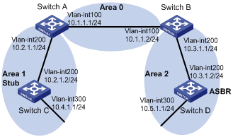
Networking and Configuration Requirements
Run OSPF on the network devices. Configure a (totally) stub area to reduce the routing table size.
Applicable Product Matrix
|
Product series |
Software version |
Hardware version |
|
S3600-EI Series Ethernet switches |
Release 1510, Release1602 |
All versions |
|
S5600 Series Ethernet switches |
Release 1510, Release1602 |
All versions |
Configuration Procedure
Non-backbone area and backbone area configuration (area 1 is a non-backbone area)
l Configure Switch A.
# Create VLANs and configure IP addresses for the VLAN interfaces. The configuration procedure is omitted.
# Configure OSPF for area 1.
<SwitchA> system-view
[SwitchA] ospf 1 router-id 1.1.1.1
[SwitchA-ospf-1] area 1
[SwitchA-ospf-1-area-0.0.0.1] network 10.2.1.0 0.0.0.255
# Configure OSPF for the backbone area.
[SwitchA-ospf-1] area 0
[SwitchA-ospf-1-area-0.0.0.0] network 10.1.1.0 0.0.0.255
l Configure Switch B (refer to the configuration on Switch A).
l Configure Switch C.
# Create VLANs and configure IP addresses for the VLAN interfaces. The configuration procedure is omitted.
# Configure OSPF for area 1.
<SwitchC> system-view
[SwitchC] ospf 1 router-id 3.3.3.3
[SwitchC-ospf-1] area 1
[SwitchC-ospf-1-area-0.0.0.1] network 10.2.1.0 0.0.0.255
[SwitchC-ospf-1-area-0.0.0.1] network 10.4.1.0 0.0.0.255
l Configure Switch D.
# Create VLANs and configure IP addresses for the VLAN interfaces. The configuration procedure is omitted.
# Configure a static route of 1.0.0.0/8.
<SwitchD> system-view
[SwitchD] ip route-static 1.0.0.0 8 10.5.1.2
# Configure OSPF for area 2.
[SwitchD] ospf 1 router-id 4.4.4.4
[SwitchD-ospf-1] area 2
[SwitchD-ospf-1-area-0.0.0.2] network 10.3.1.0 0.0.0.255
[SwitchD-ospf-1-area-0.0.0.2] network 10.5.1.0 0.0.0.255
[SwitchD-ospf-1-area-0.0.0.2] quit
# Redistribute the static route to specify Switch D as an ASBR.
[SwitchD-ospf-1] import-route static
[SwitchD-ospf-1] quit
![]()
l The above-mentioned steps configure non-backbone areas, backbone area, and ABRs/ASBRs.
l By using the display ospf lsdb command on Switch C, you can see that Type-3 LSAs, Type-4 LSAs, and Type-5 LSAs exist in the link state database (LSDB). You can control the generation of Type-4 LSAs and Type-5 LSAs by configuring the stub attribute.
Configure a stub area (area 1)
Based on the configuration in Non-backbone area and backbone area configuration (area 1 is a non-backbone area), perform the following steps:
# Configure area 1 as a stub area.
[SwitchA-ospf-1-area-0.0.0.1] stub
[SwitchC-ospf-1-area-0.0.0.1] stub
![]()
l Use the display ospf lsdb command on Switch C to display the LSDB. You can see that no Type-4 LSAs or Type-5 LSAs exist in the LSDB. But a default Type-3 LSA is added.
Configure a totally stub area (area 1 is a totally stub area)
Based on the configuration in Non-backbone area and backbone area configuration (area 1 is a non-backbone area), perform the following steps:
# Configure area 1 as a totally stub area.
[SwitchA-ospf-1-area-0.0.0.1] stub no-summary
[SwitchC-ospf-1-area-0.0.0.1] stub
![]()
l To configure a stub area as a totally stub area, use the stub no-summary command on the ABR of the stub area.
l Use the display ospf lsdb command on Switch C to display the LSDB. You can see that no Type-3 LSAs, Type-4 LSAs, or Type-5 LSAs exist in the LSDB. But a Type-3 default LSA is added.
Complete Configuration
Configuration information when area 1 is a non-backbone area:
l Perform the following configuration on Switch A.
#
vlan 100
#
vlan 200
#
interface Vlan-interface100
ip address 10.1.1.1 255.255.255.0
#
interface Vlan-interface200
ip address 10.2.1.1 255.255.255.0
#
ospf 1 router-id 1.1.1.1
area 0.0.0.1
network 10.2.1.0 0.0.0.255
#
area 0.0.0.0
network 10.1.1.0 0.0.0.255
#
l Perform the following configuration on Switch B.
#
vlan 100
#
vlan 200
#
interface Vlan-interface100
ip address 10.1.1.2 255.255.255.0
#
interface Vlan-interface200
ip address 10.3.1.1 255.255.255.0
#
ospf 1 router-id 2.2.2.2
area 0.0.0.2
network 10.3.1.0 0.0.0.255
#
area 0.0.0.0
network 10.1.1.0 0.0.0.255
#
l Perform the following configuration on Switch C.
#
vlan 200
#
vlan 300
#
interface Vlan-interface200
ip address 10.2.1.2 255.255.255.0
#
interface Vlan-interface300
ip address 10.4.1.1 255.255.255.0
#
ospf 1 router-id 3.3.3.3
area 0.0.0.1
network 10.2.1.0 0.0.0.255
network 10.4.1.0 0.0.0.255
#
l Perform the following configuration on Switch D.
#
vlan 200
#
vlan 300
#
interface Vlan-interface200
ip address 10.3.1.2 255.255.255.0
#
interface Vlan-interface300
ip address 10.5.1.1 255.255.255.0
#
ospf 1 router-id 4.4.4.4
import-route static
area 0.0.0.2
network 10.3.1.0 0.0.0.255
network 10.5.1.0 0.0.0.255
#
ip route-static 1.0.0.0 255.0.0.0 10.5.1.2 preference 60
#
Configuration information when area 1 is a stub area:
l Perform the following configuration on Switch A.
#
vlan 100
#
vlan 200
#
interface Vlan-interface100
ip address 10.1.1.1 255.255.255.0
#
interface Vlan-interface200
ip address 10.2.1.1 255.255.255.0
#
ospf 1 router-id 1.1.1.1
area 0.0.0.1
network 10.2.1.0 0.0.0.255
stub
#
area 0.0.0.0
network 10.1.1.0 0.0.0.255
#
l Perform the following configuration on Switch B.
Refer to the configuration of Switch B when area 1 is a non-backbone area.
l Perform the following configuration on Switch C.
#
vlan 200
#
vlan 300
#
interface Vlan-interface200
ip address 10.2.1.2 255.255.255.0
#
interface Vlan-interface300
ip address 10.4.1.1 255.255.255.0
#
ospf 1 router-id 3.3.3.3
area 0.0.0.1
network 10.2.1.0 0.0.0.255
network 10.4.1.0 0.0.0.255
stub
#
l Perform the following configuration on Switch D.
Refer to the configuration of Switch D when area 1 is a non-backbone area.
Configuration information when area 1 is a totally stub area:
l Perform the following configuration on Switch A.
#
vlan 100
#
vlan 200
#
interface Vlan-interface100
ip address 10.1.1.1 255.255.255.0
#
interface Vlan-interface200
ip address 10.2.1.1 255.255.255.0
#
ospf 1 router-id 1.1.1.1
area 0.0.0.1
network 10.2.1.0 0.0.0.255
stub no-summary
#
area 0.0.0.0
network 10.1.1.0 0.0.0.255
#
l Perform the following configuration on Switch B.
Refer to the configuration of Switch B when area 1 is a non-backbone area.
l Perform the following configuration on Switch C.
Refer to the configuration of Switch C when area 1 is a stub area.
l Perform the following configuration on Switch D.
Refer to the configuration of Switch D when area 1 is a non-backbone area.
Precautions
l To configure a stub area as a totally stub area, use the stub no-summary command on the ABR of the stub area.
Configuring a (Totally) NSSA Area
Refer to Configuring a (Totally) Stub Area for related information.
Network Diagram
Figure 1-6 Network diagram for (totally) NSSA area configuration
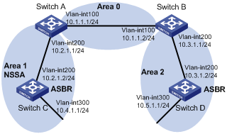
Networking and Configuration Requirements
Applicable Product Matrix
|
Product series |
Software version |
Hardware version |
|
S3600-EI Series Ethernet switches |
Release 1510, Release1602 |
All versions |
|
S5600 Series Ethernet switches |
Release 1510, Release1602 |
All versions |
Configuration Procedure
Non-backbone area and backbone area configuration (area 1 is a non-backbone area)
l Configure Switch A.
# Create VLANs and configure IP addresses for the VLAN interfaces. The configuration procedure is omitted.
# Configure OSPF for area 1.
<SwitchA> system-view
[SwitchA] ospf 1 router-id 1.1.1.1
[SwitchA-ospf-1] area 1
[SwitchA-ospf-1-area-0.0.0.1] network 10.2.1.0 0.0.0.255
# Configure OSPF for the backbone area.
[SwitchA-ospf-1] area 0
[SwitchA-ospf-1-area-0.0.0.0] network 10.1.1.0 0.0.0.255
l Configure Switch B (refer to the configuration on Switch A).
l Configure Switch C.
# Create VLANs and configure IP addresses for the VLAN interfaces. The configuration procedure is omitted.
# Configure a static route of 2.0.0.0/8.
<SwitchC> system-view
[SwitchC] ip route-static 2.0.0.0 8 10.4.1.2
# Configure OSPF for area 1.
[SwitchC] ospf 1 router-id 3.3.3.3
[SwitchC-ospf-1] area 1
[SwitchC-ospf-1-area-0.0.0.1] network 10.2.1.0 0.0.0.255
[SwitchC-ospf-1-area-0.0.0.1] network 10.4.1.0 0.0.0.255
[SwitchC-ospf-1-area-0.0.0.1] quit
# Redistribute the static route to specify Switch C as an ASBR.
[SwitchC-ospf-1] import-route static
[SwitchC-ospf-1] quit
l Configure Switch D.
# Create VLANs and configure IP addresses of the VLAN interfaces. The configuration procedure is omitted.
# Configure a static route of 1.0.0.0/8.
<SwitchD> system-view
[SwitchD] ip route-static 1.0.0.0 8 10.5.1.2
# Configure OSPF for area 2.
[SwitchD] ospf 1 router-id 4.4.4.4
[SwitchD-ospf-1] area 2
[SwitchD-ospf-1-area-0.0.0.2] network 10.3.1.0 0.0.0.255
[SwitchD-ospf-1-area-0.0.0.2] network 10.5.1.0 0.0.0.255
[SwitchD-ospf-1-area-0.0.0.2] quit
# Redistribute the static route to specify Switch D as an ASBR.
[SwitchD-ospf-1] import-route static
[SwitchD-ospf-1] quit
![]()
l The above-mentioned steps configure non-backbone areas, backbone area, and ABRs/ASBRs.
l By using the display ospf lsdb command on Switch C, you can see that Type-3 LSAs, Type-4 LSAs, and Type-5 LSAs exist in the link state database (LSDB).
NSSA area configuration 1 (area 1 is an NSSA area)
![]()
After this configuration, packets destined for an IP address (in another AS) advertised by the ASBR of the NSSA area will be forwarded by the ASBR, while packets destined for an IP address (in another AS) not advertised by the ASBR will be dropped.
Based on the configuration in Non-backbone area and backbone area configuration (area 1 is a non-backbone area), perform the following steps:
# Configure area 1 as an NSSA area.
[SwitchA-ospf-1-area-0.0.0.1] nssa
[SwitchC-ospf-1-area-0.0.0.1] nssa
![]()
l The steps above configure an NSSA area.
l Use the display ospf lsdb command on Switch C to display the LSDB. You can see that no Type-4 LSAs or Type-5 LSAs exist in the LSDB. But Type-7 LSAs are installed.
NSSA area configuration 2 (area 1 is an NSSA area)
![]()
After this configuration, packets from the NSSA area to other ASs are forwarded by the ASBR of the NSSA area.
Based on the configuration in Non-backbone area and backbone area configuration (area 1 is a non-backbone area), perform the following steps:
# Configure a default route.
[SwitchC] ip route-static 0.0.0.0 0.0.0.0 10.4.1.2
# Configure Area 1 as an NSSA area. Switch C will forward all the packets to other ASs.
[SwitchA-ospf-1-area-0.0.0.1] nssa
[SwitchC-ospf-1-area-0.0.0.1] nssa default-route-advertise
![]()
l The steps above configure an NSSA area.
l Use the display ospf lsdb command on Switch C to display the LSDB. You can see that no Type-4 LSAs or Type-5 LSAs exist in the LSDB. But Type-7 LSAs and a Type-7 default LSA are added.
NSSA area configuration 3 (area 1 is an NSSA area)
![]()
After this configuration, packets destined for an IP address (in another AS) advertised by the ASBR of the NSSA area will be forwarded by the ASBR, while packets destined for an IP address (in another AS) not advertised by the ASBR will be forward by the ABR of the area to the ASBR of another area for further forwarding.
Based on the configuration in Non-backbone area and backbone area configuration (area 1 is a non-backbone area), perform the following steps:
# Configure area 1 as an NSSA area.
[SwitchA-ospf-1-area-0.0.0.1] nssa default-route-advertise
[SwitchC-ospf-1-area-0.0.0.1] nssa
![]()
l The steps above configure an NSSA area.
l Use the display ospf lsdb command on Switch C to display the LSDB. You can see that no Type-4 LSAs or Type-5 LSAs exist in the LSDB. But Type-7 LSAs and a Type-7 default LSA are installed.
Totally NSSA area configuration (area 1 is a totally NSSA area)
Based on the configuration in Non-backbone area and backbone area configuration (area 1 is a non-backbone area), perform the following steps:
# Configure area 1 as a totally NSSA area.
[SwitchA-ospf-1-area-0.0.0.1] nssa no-summary
[SwitchC-ospf-1-area-0.0.0.1] nssa
![]()
l The steps above configure a totally NSSA area.
l Use the display ospf lsdb command on Switch C to display the LSDB. You can see that no Type-3 LSAs, Type-4 LSAs, or Type-5 LSAs exist in the LSDB. But Type-7 LSAs and a default Type-3 LSA are added.
Complete Configuration
![]()
In the following example, the ASBR of the NSSA area will forward all the packets destined for other ASs. For the configurations in other cases, refer to Configuration Procedure.
l Perform the following configuration on Switch A.
#
vlan 100
#
vlan 200
#
interface Vlan-interface100
ip address 10.1.1.1 255.255.255.0
#
interface Vlan-interface200
ip address 10.2.1.1 255.255.255.0
#
ospf 1 router-id 1.1.1.1
area 0.0.0.1
network 10.2.1.0 0.0.0.255
nssa
#
area 0.0.0.0
network 10.1.1.0 0.0.0.255
#
l Perform the following configuration on Switch B.
#
vlan 100
#
vlan 200
#
interface Vlan-interface100
ip address 10.1.1.2 255.255.255.0
#
interface Vlan-interface200
ip address 10.3.1.1 255.255.255.0
#
ospf 1 router-id 2.2.2.2
area 0.0.0.2
network 10.3.1.0 0.0.0.255
#
area 0.0.0.0
network 10.1.1.0 0.0.0.255
#
l Perform the following configuration on Switch C.
#
vlan 200
#
vlan 300
#
interface Vlan-interface200
ip address 10.2.1.2 255.255.255.0
#
interface Vlan-interface300
ip address 10.4.1.1 255.255.255.0
#
ospf 1 router-id 3.3.3.3
import-route static
area 0.0.0.1
network 10.2.1.0 0.0.0.255
network 10.4.1.0 0.0.0.255
nssa default-route-advertise
#
ip route-static 0.0.0.0 0.0.0.0 10.4.1.2 preference 60
ip route-static 2.0.0.0 255.0.0.0 10.4.1.2 preference 60
#
l Perform the following configuration on Switch D.
#
vlan 200
#
vlan 300
#
interface Vlan-interface200
ip address 10.3.1.2 255.255.255.0
#
interface Vlan-interface300
ip address 10.5.1.1 255.255.255.0
#
ospf 1 router-id 4.4.4.4
import-route static
area 0.0.0.2
network 10.3.1.0 0.0.0.255
network 10.5.1.0 0.0.0.255
#
ip route-static 1.0.0.0 255.0.0.0 10.5.1.2 preference 60
#
Precautions
l To configure an NSSA area as a totally NSSA area, use the nssa no-summary command on the ABR of the NSSA area.
l After you configure an area as a totally NSSA area, the ABR of the totally NSSA area will automatically generate a Type-3 default LSA into the totally NSSA area.
l For the ABR of an NSSA area to generate a default Type-7 LSA, you only need to execute the nssa default-route-advertise command on it.
Configuring OSPF Route Summarization
You can configure an ABR or ASBR to summarize routes with the same prefix into a single route and distribute it to other areas.
An AS is divided into different areas that are interconnected through ABRs. Through route summarization, routing information across areas and the size of routing tables on routers will be reduced, improving the calculation speed of routers.
After calculating the intra-area routes of an area, an ABR summarizes contiguous networks into one route and advertises it to other areas according to the related configuration.
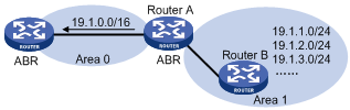
For example, as shown in the following figure, in Area 1 are three intra-area routes 19.1.1.0/24, 19.1.2.0/24, and 19.1.3.0/24. By configuring route summarization on Router A, the three routes are summarized with the route 19.1.0.0/16 that is advertised into Area 0.
Figure 1-7 Route summarization
OSPF performs two types of route summarization:
1) ABR route summarization
To distribute routing information to other areas, an ABR generates Type-3 LSAs on a per network segment basis. If contiguous network segments are available in the area, you can summarize them with a single network segment. In this way, the ABR in the area distributes only the summary LSA to reduce the scale of LSDBs on routers in other areas.
2) ASBR route summarization
If summarization for redistributed routes is configured on an ASBR, it will summarize redistributed Type-5 LSAs that fall into the specified address range. If in an NSSA area, it also summarizes Type-7 LSAs that fall into the specified address range.
Network Diagram
Figure 1-8 Network diagram for route summarization configuration

Networking and Configuration Requirements
Applicable Product Matrix
|
Product series |
Software version |
Hardware version |
|
S3600-EI Series Ethernet switches |
Release 1510, Release1602 |
All versions |
|
S5600 Series Ethernet switches |
Release 1510, Release1602 |
All versions |
Configuration Procedure
OSPF basic configuration and area configuration
l Configure Switch A.
# Create VLANs and configure IP addresses for the VLAN interfaces. The configuration procedure is omitted.
# Configure OSPF basic functions. The configuration procedure is omitted.
# Configure the NSSA attribute of Switch A.
<SwitchA> system-view
[SwitchA] ospf 1
[SwitchA-ospf-1] area 1
[SwitchA-ospf-1-area-0.0.0.1] nssa
[SwitchA-ospf-1-area-0.0.0.1] quit
l Configure Switch C.
# Create VLANs and configure IP addresses for the VLAN interfaces. The configuration procedure is omitted.
# Configure OSPF basic functions. The configuration procedure is omitted.
# Configure the static routes 2.1.3.0/24, 2.1.4.0/24, 2.1.5.0/24, 2.1.6.0/24, and 2.1.7.0/24.
<SwitchC> system-view
[SwitchC] ip route-static 2.1.3.0 24 20.1.2.2
[SwitchC] ip route-static 2.1.4.0 24 20.1.2.2
[SwitchC] ip route-static 2.1.5.0 24 20.1.2.2
[SwitchC] ip route-static 2.1.6.0 24 20.1.2.2
[SwitchC] ip route-static 2.1.7.0 24 20.1.2.2
# Redistribute the static routes and configure the NSSA attribute of Switch C.
[SwitchC] ospf 1
[SwitchC-ospf-1] import-route static
[SwitchC-ospf-1] area 1
[SwitchC-ospf-1-area-0.0.0.1] nssa
[SwitchC-ospf-1-area-0.0.0.1] quit
l Configure Switch B.
# Create VLANs and configure IP addresses for the VLAN interfaces. The configuration procedure is omitted.
# Configure OSPF basic functions. The configuration procedure is omitted.
l Configure Switch D.
# Create VLANs and configure IP addresses for the VLAN interfaces. The configuration procedure is omitted.
# Configure OSPF basic functions. The configuration procedure is omitted.
# Configure the static routes 1.1.3.0/24, 1.1.4.0/24, 1.1.5.0/24, 1.1.6.0/24, and 1.1.7.0/24.
<SwitchD> system-view
[SwitchD] ip route-static 1.1.3.0 24 30.1.2.2
[SwitchD] ip route-static 1.1.4.0 24 30.1.2.2
[SwitchD] ip route-static 1.1.5.0 24 30.1.2.2
[SwitchD] ip route-static 1.1.6.0 24 30.1.2.2
[SwitchD] ip route-static 1.1.7.0 24 30.1.2.2
# Redistribute the static routes.
[SwitchD] ospf 1
[SwitchD-ospf-1] import-route static
ABR route summarization configuration
![]()
This configuration is applicable when an ABR needs to summarize the Type-3 LSAs of an area. The following takes the ABR route summarization configuration on Switch B as an example.
Based on OSPF basic configuration and area configuration, perform the following configuration:
# Configure ABR route summarization to summarize the routes 30.1.1.0/24 and 30.1.2.0/24 in area 2 into 30.1.0.0/22.
[SwitchB-ospf-1] area 2
[SwitchB-ospf-1-area-0.0.0.2] abr-summary 30.1.0.0 255.255.252.0
[SwitchB-ospf-1-area-0.0.0.2] quit
ASBR route summarization configuration 1
![]()
This configuration is applicable when an ASBR needs to summarize the Type-5 LSAs or Type-7 LSAs. The following takes the ASBR route summarization configuration on Switch D as an example.
Based on OSPF basic configuration and area configuration, perform the following configuration:
# Configure ASBR route summarization to summarize the routes 1.1.4.0/24, 1.1.5.0/24, 1.1.6.0/24, and 1.1.7.0/24 into 1.1.4.0/22 and to prevent 1.1.3.0/24 from being advertised to any other area.
[SwitchD-ospf-1] asbr-summary 1.1.4.0 255.255.252.0
[SwitchD-ospf-1] asbr-summary 1.1.3.0 255.255.255.0 not-advertise
ASBR route summarization configuration 2
![]()
This configuration is applicable when the ABR in an NSSA area needs to translate Type-7 LSAs into Type-5 LSAs and summarize the Type-5 LSAs.
Based on OSPF basic configuration and area configuration, perform the following configuration:
# Switch A is the ABR of the NSSA area. Configure ASBR route summarization to summarize the routes 2.1.4.0/24, 2.1.5.0/24, 2.1.6.0/24, and 2.1.7.0/24 into 2.1.4.0/22 and to prevent 2.1.3.0/24 from being advertised.
[SwitchA-ospf-1] asbr-summary 2.1.4.0 255.255.252.0
[SwitchA-ospf-1] asbr-summary 2.1.3.0 255.255.255.0 not-advertise
Complete Configuration
ABR route summarization configuration
![]()
Configure ABR route summarization on Switch B.
l Perform the following configuration on Switch A.
#
vlan 100
#
vlan 200
#
interface Vlan-interface100
ip address 10.1.1.1 255.255.255.0
#
interface Vlan-interface200
ip address 20.1.1.1 255.255.255.0
#
ospf 1 router-id 1.1.1.1
area 0.0.0.1
network 20.1.1.0 0.0.0.255
nssa
#
area 0.0.0.0
network 10.1.1.0 0.0.0.255
#
l Perform the following configuration on Switch B.
#
vlan 100
#
vlan 200
#
interface Vlan-interface100
ip address 10.1.1.2 255.255.255.0
#
interface Vlan-interface200
ip address 30.1.1.1 255.255.255.0
#
ospf 1 router-id 2.2.2.2
area 0.0.0.2
network 30.1.1.0 0.0.0.255
abr-summary 30.1.0.0 255.255.252.0 advertise
#
area 0.0.0.0
network 10.1.1.0 0.0.0.255
#
l Perform the following configuration on Switch C.
#
vlan 200
#
vlan 300
#
interface Vlan-interface200
ip address 20.1.1.2 255.255.255.0
#
interface Vlan-interface300
ip address 20.1.2.1 255.255.255.0
#
ospf 1 router-id 3.3.3.3
import-route static
area 0.0.0.2
network 20.1.1.0 0.0.0.255
network 20.1.2.0 0.0.0.255
nssa
#
ip route-static 2.1.3.0 255.255.255.0 20.1.2.2 preference 60
ip route-static 2.1.4.0 255.255.255.0 20.1.2.2 preference 60
ip route-static 2.1.5.0 255.255.255.0 20.1.2.2 preference 60
ip route-static 2.1.6.0 255.255.255.0 20.1.2.2 preference 60
ip route-static 2.1.7.0 255.255.255.0 20.1.2.2 preference 60
#
l Perform the following configuration on Switch D.
#
vlan 200
#
vlan 300
#
interface Vlan-interface200
ip address 30.1.1.2 255.255.255.0
#
interface Vlan-interface300
ip address 30.1.2.1 255.255.255.0
#
ospf 1 router-id 4.4.4.4
import-route static
area 0.0.0.2
network 30.1.1.0 0.0.0.255
network 30.1.2.0 0.0.0.255
#
ip route-static 1.1.3.0 255.255.255.0 30.1.2.2 preference 60
ip route-static 1.1.4.0 255.255.255.0 30.1.2.2 preference 60
ip route-static 1.1.5.0 255.255.255.0 30.1.2.2 preference 60
ip route-static 1.1.6.0 255.255.255.0 30.1.2.2 preference 60
ip route-static 1.1.7.0 255.255.255.0 30.1.2.2 preference 60
#
ASBR route summarization configuration 1
![]()
Configure ASBR route summarization on Switch D.
l Configure Switch A.
#
vlan 100
#
vlan 200
#
interface Vlan-interface100
ip address 10.1.1.1 255.255.255.0
#
interface Vlan-interface200
ip address 20.1.1.1 255.255.255.0
#
ospf 1 router-id 1.1.1.1
area 0.0.0.1
network 20.1.1.0 0.0.0.255
nssa
#
area 0.0.0.0
network 10.1.1.0 0.0.0.255
#
l Configure Switch B.
#
vlan 100
#
vlan 200
#
interface Vlan-interface100
ip address 10.1.1.2 255.255.255.0
#
interface Vlan-interface200
ip address 30.1.1.1 255.255.255.0
#
ospf 1 router-id 2.2.2.2
area 0.0.0.2
network 30.1.1.0 0.0.0.255
#
area 0.0.0.0
network 10.1.1.0 0.0.0.255
#
l Configure Switch C.
#
vlan 200
#
vlan 300
#
interface Vlan-interface200
ip address 20.1.1.2 255.255.255.0
#
interface Vlan-interface300
ip address 20.1.2.1 255.255.255.0
#
ospf 1 router-id 3.3.3.3
import-route static
area 0.0.0.2
network 20.1.1.0 0.0.0.255
network 20.1.2.0 0.0.0.255
nssa
#
ip route-static 2.1.3.0 255.255.255.0 20.1.2.2 preference 60
ip route-static 2.1.4.0 255.255.255.0 20.1.2.2 preference 60
ip route-static 2.1.5.0 255.255.255.0 20.1.2.2 preference 60
ip route-static 2.1.6.0 255.255.255.0 20.1.2.2 preference 60
ip route-static 2.1.7.0 255.255.255.0 20.1.2.2 preference 60
#
l Configure Switch D.
#
vlan 200
#
vlan 300
#
interface Vlan-interface200
ip address 30.1.1.2 255.255.255.0
#
interface Vlan-interface300
ip address 30.1.2.1 255.255.255.0
#
ospf 1 router-id 4.4.4.4
asbr-summary 1.1.4.0 255.255.252.0
asbr-summary 1.1.3.0 255.255.255.0 not-advertise
import-route static
area 0.0.0.2
network 30.1.1.0 0.0.0.255
network 30.1.2.0 0.0.0.255
#
ip route-static 1.1.3.0 255.255.255.0 30.1.2.2 preference 60
ip route-static 1.1.4.0 255.255.255.0 30.1.2.2 preference 60
ip route-static 1.1.5.0 255.255.255.0 30.1.2.2 preference 60
ip route-static 1.1.6.0 255.255.255.0 30.1.2.2 preference 60
ip route-static 1.1.7.0 255.255.255.0 30.1.2.2 preference 60
#
ASBR route summarization configuration 2
![]()
Configure ASBR route summarization on Switch A to summarize the Type-5 LSAs translated from Type-7 LSAs.
l Configure Switch A.
#
vlan 100
#
vlan 200
#
interface Vlan-interface100
ip address 10.1.1.1 255.255.255.0
#
interface Vlan-interface200
ip address 20.1.1.1 255.255.255.0
#
ospf 1 router-id 1.1.1.1
asbr-summary 2.1.4.0 255.255.252.0
asbr-summary 2.1.3.0 255.255.255.0 not-advertise
area 0.0.0.1
network 20.1.1.0 0.0.0.255
nssa
#
area 0.0.0.0
network 10.1.1.0 0.0.0.255
#
l Configure Switch B.
#
vlan 100
#
vlan 200
#
interface Vlan-interface100
ip address 10.1.1.2 255.255.255.0
#
interface Vlan-interface200
ip address 30.1.1.1 255.255.255.0
#
ospf 1 router-id 2.2.2.2
area 0.0.0.2
network 30.1.1.0 0.0.0.255
#
area 0.0.0.0
network 10.1.1.0 0.0.0.255
#
l Configure Switch C.
#
vlan 200
#
vlan 300
#
interface Vlan-interface200
ip address 20.1.1.2 255.255.255.0
#
interface Vlan-interface300
ip address 20.1.2.1 255.255.255.0
#
ospf 1 router-id 3.3.3.3
import-route static
area 0.0.0.2
network 20.1.1.0 0.0.0.255
network 20.1.2.0 0.0.0.255
nssa
#
ip route-static 2.1.3.0 255.255.255.0 20.1.2.2 preference 60
ip route-static 2.1.4.0 255.255.255.0 20.1.2.2 preference 60
ip route-static 2.1.5.0 255.255.255.0 20.1.2.2 preference 60
ip route-static 2.1.6.0 255.255.255.0 20.1.2.2 preference 60
ip route-static 2.1.7.0 255.255.255.0 20.1.2.2 preference 60
#
l Configure Switch D.
#
vlan 200
#
vlan 300
#
interface Vlan-interface200
ip address 30.1.1.2 255.255.255.0
#
interface Vlan-interface300
ip address 30.1.2.1 255.255.255.0
#
ospf 1 router-id 4.4.4.4
import-route static
area 0.0.0.2
network 30.1.1.0 0.0.0.255
network 30.1.2.0 0.0.0.255
#
ip route-static 1.1.3.0 255.255.255.0 30.1.2.2 preference 60
ip route-static 1.1.4.0 255.255.255.0 30.1.2.2 preference 60
ip route-static 1.1.5.0 255.255.255.0 30.1.2.2 preference 60
ip route-static 1.1.6.0 255.255.255.0 30.1.2.2 preference 60
ip route-static 1.1.7.0 255.255.255.0 30.1.2.2 preference 60
#
Precautions
l After the asbr-summary command is used on an ASBR, it will summarize the Type-5 LSAs falling into the specified address range; if the ASBR is in an NSSA area, it will summarize the Type-7 LSAs within the specified address range. If used on the ABR of an NSSA area, the asbr-summary command summarizes Type-5 LSAs translated from Type-7 LSAs. If the router is not the ABR in the NSSA area, no summarization is performed. You can use the not-advertise keyword to not advertise a specified summary route in a LSA.
Configuring OSPF Virtual Link
Among OSPF areas in an AS, one area is different from any other area. Its area ID is 0 and it is usually called the backbone area. The backbone area is responsible for distributing routing information between none-backbone areas. Therefore, OSPF requires that:
l All non-backbone areas must maintain connectivity to the backbone area.
l The backbone area must maintain connectivity within itself.
In practice, the requirements may not be satisfied due to physical limitations. In this case, configuring OSPF virtual links is a solution.
Network Diagram
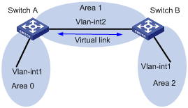
Figure 1-9 Networking diagram for OSPF virtual link
|
Device |
Interface |
IP address |
Router ID |
|
Switch A |
Vlan-int1 |
196.1.1.2/24 |
1.1.1.1 |
|
|
Vlan-int2 |
197.1.1.2/24 |
- |
|
Switch B |
Vlan-int1 |
152.1.1.1/24 |
2.2.2.2 |
|
|
Vlan-int2 |
197.1.1.1/24 |
- |
Networking and Configuration Requirements
Configure OSPF in the network, which is divided into three areas: the backbone area and two non-backbone areas (Area 1 and Area 2). Area 2 has no direct connection to the backbone area; the connection from Area 2 to the backbone area must go through Area 1. The user hopes to enable Area 2 to communicate with the other two areas.
Applicable Product Matrix
|
Product series |
Software version |
Hardware version |
|
S3600-EI Series Ethernet switches |
Release 1510, Release1602 |
All versions |
|
S5600 Series Ethernet switches |
Release 1510, Release1602 |
All versions |
Configuration Procedure
1) Configure OSPF basic functions.
# Configure Switch A.
<SwitchA> system-view
[SwitchA] interface vlan-interface 1
[SwitchA-Vlan-interface1] ip address 196.1.1.2 255.255.255.0
[SwitchA-Vlan-interface1] quit
[SwitchA] interface vlan-interface 2
[SwitchA-Vlan-interface2] ip address 197.1.1.2 255.255.255.0
[SwitchA-Vlan-interface2] quit
[SwitchA] router id 1.1.1.1
[SwitchA] ospf
[SwitchA-ospf-1] area 0
[SwitchA-ospf-1-area-0.0.0.0] network 196.1.1.0 0.0.0.255
[SwitchA-ospf-1-area-0.0.0.0] quit
[SwitchA-ospf-1] area 1
[SwitchA-ospf-1-area-0.0.0.1] network 197.1.1.0 0.0.0.255
[SwitchA-ospf-1-area-0.0.0.1] quit
# Configure Switch B.
<SwitchB> system-view
[SwitchB] interface Vlan-interface 1
[SwitchB-Vlan-interface1] ip address 152.1.1.1 255.255.255.0
[SwitchB-Vlan-interface1] quit
[SwitchB] interface Vlan-interface 2
[SwitchB-Vlan-interface2] ip address 197.1.1.1 255.255.255.0
[SwitchB-Vlan-interface2] quit
[SwitchB] router id 2.2.2.2
[SwitchB] ospf
[SwitchB-ospf-1] area 1
[SwitchB-ospf-1-area-0.0.0.1] network 197.1.1.0 0.0.0.255
[SwitchB-ospf-1-area-0.0.0.1] quit
[SwitchB-ospf-1] area 2
[SwitchB-ospf-1-area-0.0.0.2] network 152.1.1.0 0.0.0.255
[SwitchB-ospf-1-area-0.0.0.2] quit
2) Configure a virtual link.
# Configure Switch A.
[SwitchA-ospf-1] area 1
[SwitchA-ospf-1-area-0.0.0.1] vlink-peer 2.2.2.2
[SwitchA-ospf-1-area-0.0.0.1] quit
[SwitchA-ospf-1] quit
# Configure Switch B.
[SwitchB-ospf-1] area 1
[SwitchB-ospf-1-area-0.0.0.1] vlink-peer 1.1.1.1
[SwitchB-ospf-1-area-0.0.0.1] quit
Complete Configuration
l Perform the following configuration on Switch A.
#
router id 1.1.1.1
#
vlan 1
#
vlan 2
#
interface Vlan-interface1
ip address 196.1.1.2 255.255.255.0
#
interface Vlan-interface2
ip address 197.1.1.2 255.255.255.0
#
ospf 1
area 0.0.0.0
network 196.1.1.0 0.0.0.255
area 0.0.0.1
network 197.1.1.0 0.0.0.255
vlink-peer 2.2.2.2
#
l Perform the following configuration on Switch B.
#
router id 2.2.2.2
#
vlan 1
#
vlan 2
#
interface Vlan-interface1
ip address 152.1.1.1 255.255.255.0
#
interface Vlan-interface2
ip address 197.1.1.1 255.255.255.0
#
ospf 1
area 0.0.0.1
network 197.1.1.0 0.0.0.255
vlink-peer 1.1.1.1
area 0.0.0.2
network 152.1.1.0 0.0.0.255
#
Precautions
l Both ends of a virtual link must be ABRs configured with the vlink-peer command.
l A virtual link cannot transit the backbone area.
l The vlink-peer command needs to be used in the transit area.
Configuring BGP Confederation Attribute
Border gateway protocol (BGP) is a dynamic routing protocol designed to be employed among autonomous systems (AS). An AS is a group of routers that adopt the same routing policy and belong to the same technical management department.
Confederation is another way to limit the number of IBGP connections in an AS. It divides an AS into multiple sub-ASs. The IBGP peers in each sub-AS are fully connected.
Network Diagram
Figure 1-10 Network diagram for AS confederation configuration
|
Device |
Interface |
IP address |
AS |
|
Switch A |
Vlan-int 10 |
172.68.10.1/24 |
100 |
|
Switch B |
Vlan-int 10 |
172.68.10.2/24 |
|
|
Switch C |
Vlan-int 10 |
172.68.10.3/24 |
|
|
|
Vlan-int 20 |
172.68.1.1/24 |
|
|
|
Vlan-int 30 |
156.10.1.1/24 |
|
|
Switch D |
Vlan-int 20 |
172.68.1.2/24 |
|
|
Switch E |
Vlan-int 30 |
156.10.1.2/24 |
200 |
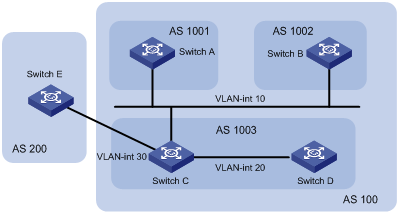
Networking and Configuration Requirements
l Split AS 100 into three sub-ASs: AS 1001, AS 1002, and AS 1003.
l Run EBGP between AS 1001, AS 1002, and AS 1003.
l AS 1001, AS 1002, and AS 1003 are each fully meshed by running IBGP.
l Run EBGP between AS 100 and AS 200.
Applicable Product Matrix
|
Product series |
Software version |
Hardware version |
|
S5600 Series Ethernet switches |
Release 1510, Release1602 |
All versions |
Configuration Procedure
# Configure Switch A.
<SwitchA> system-view
[SwitchA] bgp 1001
[SwitchA-bgp] confederation id 100
[SwitchA-bgp] confederation peer-as 1002 1003
[SwitchA-bgp] group confed1002 external
[SwitchA-bgp] peer 172.68.10.2 group confed1002 as-number 1002
[SwitchA-bgp] group confed1003 external
[SwitchA-bgp] peer 172.68.10.3 group confed1003 as-number 1003
# Configure Switch B.
<SwitchB> system-view
[SwitchB] bgp 1002
[SwitchB-bgp] confederation id 100
[SwitchB-bgp] confederation peer-as 1001 1003
[SwitchB-bgp] group confed1001 external
[SwitchB-bgp] peer 172.68.10.1 group confed1001 as-number 1001
[SwitchB-bgp] group confed1003 external
[SwitchB-bgp] peer 172.68.10.3 group confed1003 as-number 1003
# Configure Switch C.
<SwitchC> system-view
[SwitchC] bgp 1003
[SwitchC-bgp] confederation id 100
[SwitchC-bgp] confederation peer-as 1001 1002
[SwitchC-bgp] group confed1001 external
[SwitchC-bgp] peer 172.68.10.1 group confed1001 as-number 1001
[SwitchC-bgp] group confed1002 external
[SwitchC-bgp] peer 172.68.10.2 group confed1002 as-number 1002
[SwitchC-bgp] group ebgp200 external
[SwitchC-bgp] peer 156.10.1.2 group ebgp200 as-number 200
[SwitchC-bgp] group ibgp1003 internal
[SwitchC-bgp] peer 172.68.1.2 group ibgp1003
Complete Configuration
l Configure Switch A.
#
bgp 1001
confederation id 100
confederation peer-as 1002 1003
undo synchronization
group confed1002 external
peer 172.68.10.2 group confed1002 as-number 1002
group confed1003 external
peer 172.68.10.3 group confed1003 as-number 1003
#
l Configure Switch B.
#
bgp 1002
confederation id 100
confederation peer-as 1001 1003
undo synchronization
group confed1001 external
peer 172.68.10.1 group confed1001 as-number 1001
group confed1003 external
peer 172.68.10.3 group confed1003 as-number 1003
#
l Configure Switch C.
#
bgp 1003
confederation id 100
confederation peer-as 1001 1002
undo synchronization
group ebgp200 external
peer 156.10.1.2 group ebgp200 as-number 200
group confed1001 external
peer 172.68.10.1 group confed1001 as-number 1001
group confed1002 external
peer 172.68.10.2 group confed1002 as-number 1002
group ibgp1003 internal
peer 172.68.1.2 group ibgp1003
#
Precautions
l If you want to use confederation, you need to determine the confederation ID and the sub-AS number.
l A confederation can include up to 32 sub-ASs. The AS number used by a sub-AS which is configured to belong to a confederation is only valid inside the confederation.
l If the confederation implementation mechanism of other routers is different from the RFC standardization, you can configure related command to make the confederation compatible with the non-standard routers.
Configuring BGP RR
To ensure the connectivity among the IBGP peers in an AS, you need to make the IBGP peers fully connected. For an AS with the number of the routers in it being n, you need to establish at least n*(n-1)/2 IBGP connections to make them fully connected. This requires large amount of network resources and CPU time if large amount of IBGP peers exist in the AS.
You can decrease the use of network resources and CPU time through route reflection in this case. That is, use a router as a router reflector (RR) and establish IBGP connections between the RR and other routers known as clients. Routing information exchanged between the clients is passed/reflected by the RR. This eliminates the need to establish IBGP connections among the clients.
Network Diagram
Figure 1-11 Network diagram for BGP RR configuration
|
Device |
Interface |
IP address |
AS |
|
Switch A |
Vlan-int 100 |
1.1.1.1/8 |
100 |
|
|
Vlan-int 2 |
192.1.1.1/24 |
|
|
Switch B |
Vlan-int 2 |
192.1.1.2/24 |
200 |
|
|
Vlan-int 3 |
193.1.1.2/24 |
|
|
Switch C |
Vlan-int 3 |
193.1.1.1/24 |
|
|
|
Vlan-int 4 |
194.1.1.1/24 |
|
|
Switch D |
Vlan-int 4 |
194.1.1.2/24 |
|
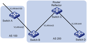
Networking and Configuration Requirements
l Run EBGP between the peers in AS 100 and AS 200. Inject network 1.0.0.0/8.
l Run IBGP between the peers in AS 200. Configure a star topology for the AS. Specify the central device as a route reflector and other devices as clients.
Applicable Product Matrix
|
Product series |
Software version |
Hardware version |
|
S5600 Series Ethernet switches |
Release 1510, Release1602 |
All versions |
Configuration Procedure
1) Configure Switch A.
<SwitchA> system-view
[SwitchA] interface Vlan-interface 2
[SwitchA-Vlan-interface2] ip address 192.1.1.1 255.255.255.0
[SwitchA-Vlan-interface2] quit
[SwitchA] interface Vlan-interface 100
[SwitchA-Vlan-interface100] ip address 1.1.1.1 255.0.0.0
[SwitchA-Vlan-interface100] quit
[SwitchA] bgp 100
[SwitchA-bgp] group ex external
[SwitchA-bgp] peer 192.1.1.2 group ex as-number 200
[SwitchA-bgp] network 1.0.0.0 255.0.0.0
2) Configure Switch B.
# Configure VLAN interface IP addresses.
<SwitchB> system-view
[SwitchB] interface Vlan-interface 2
[SwitchB-Vlan-interface2] ip address 192.1.1.2 255.255.255.0
[SwitchB-Vlan-interface2] quit
[SwitchB] interface Vlan-interface 3
[SwitchB-Vlan-interface3] ip address 193.1.1.2 255.255.255.0
[SwitchB-Vlan-interface3] quit
# Configure a BGP peer.
[SwitchB] bgp 200
[SwitchB-bgp] group ex external
[SwitchB-bgp] peer 192.1.1.1 group ex as-number 100
[SwitchB-bgp] group in internal
[SwitchB-bgp] peer 193.1.1.1 group in
3) Configure Switch C.
# Configure VLAN interface IP addresses.
<SwitchC> system-view
[SwitchC] interface Vlan-interface 3
[SwitchC-Vlan-interface3] ip address 193.1.1.1 255.255.255.0
[SwitchC-Vlan-interface3] quit
[SwitchC] interface vlan-Interface 4
[SwitchC-Vlan-interface4] ip address 194.1.1.1 255.255.255.0
[SwitchC-Vlan-interface4] quit
# Configure BGP peers and RR.
[SwitchC] bgp 200
[SwitchC-bgp] group rr internal
[SwitchC-bgp] peer rr reflect-client
[SwitchC-bgp] peer 193.1.1.2 group rr
[SwitchC-bgp] peer 194.1.1.2 group rr
4) Configure Switch D.
# Configure VLAN interface IP address.
<SwitchD> system-view
[SwitchD] interface vlan-interface 4
[SwitchD-Vlan-interface4] ip address 194.1.1.2 255.255.255.0
[SwitchD-Vlan-interface4] quit
# Configure a BGP peer.
[SwitchD] bgp 200
[SwitchD-bgp] group in internal
[SwitchD-bgp] peer 194.1.1.1 group in
Use the display bgp routing command to display the BGP routing table on Switch B. Note that, Switch B has already known the existence of network 1.0.0.0.
Use the display bgp routing command to display the BGP routing table on Switch D. Note that, Switch D knows the existence of network 1.0.0.0, too.
Complete Configuration
l Configure Switch A.
#
vlan 1 to 2
#
vlan 100
#
interface Vlan-interface2
ip address 192.1.1.1 255.255.255.0
#
interface Vlan-interface100
ip address 1.1.1.1 255.0.0.0
#
bgp 100
network 1.0.0.0
undo synchronization
group ex external
peer 192.1.1.2 group ex as-number 200
#
l Configure Switch B.
#
vlan 1 to 3
#
interface Vlan-interface2
ip address 192.1.1.2 255.255.255.0
#
interface Vlan-interface3
ip address 193.1.1.2 255.255.255.0
#
bgp 200
undo synchronization
group ex external
peer 192.1.1.1 group ex as-number 100
group in internal
peer 193.1.1.1 group in
#
l Configure Switch C.
#
vlan 1
#
vlan 3 to 4
#
interface Vlan-interface3
ip address 193.1.1.1 255.255.255.0
#
interface Vlan-interface4
ip address 194.1.1.1 255.255.255.0
#
bgp 200
undo synchronization
group rr internal
peer rr reflect-client
peer 193.1.1.2 group rr
peer 194.1.1.2 group rr
#
l Configure Switch D.
#
vlan 1
#
vlan 4
#
interface Vlan-interface4
ip address 194.1.1.2 255.255.255.0
#
bgp 200
undo synchronization
group in internal
peer 194.1.1.1 group in
#
Precautions
l Note that a BGP router which is neither the RR nor a client is called a non-client. Non-clients and the RR must be fully connected.
l Normally, full connection is not required between an RR and a client. A route is reflected by an RR from a client to another client. If an RR and a client are fully connected, you can disable the reflection between clients to reduce the cost.
l Normally, there is only one RR in a cluster. In this case, the router ID of the RR is used to identify the cluster. Configuring multiple RRs can improve the network stability. If there are multiple RRs in a cluster, use related command to configure the same cluster ID for them to avoid routing loopback.
Configuring BGP Path Selection
Network Diagram
Figure 1-12 Network diagram for BGP path selection
|
Device |
Interface |
IP address |
AS |
|
Switch A |
Vlan-int 101 |
1.1.1.1/8 |
100 |
|
|
Vlan-int 2 |
192.1.1.1/24 |
|
|
|
Vlan-int 3 |
193.1.1.1/24 |
|
|
Switch B |
Vlan-int 2 |
192.1.1.2/24 |
200 |
|
|
Vlan-int 4 |
194.1.1.2/24 |
|
|
Switch C |
Vlan-int 3 |
193.1.1.2/24 |
|
|
|
Vlan-int 5 |
195.1.1.2/24 |
|
|
Switch D |
Vlan-int 4 |
194.1.1.1/24 |
|
|
|
Vlan-int 5 |
195.1.1.1/24 |
|
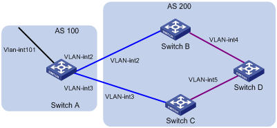
Networking and Configuration Requirements
l Run EBGP between AS 100 and AS 200. Inject network 1.0.0.0/8.
l Run OSPF in AS 200 to realize network interconnection.
l Run IBGP between Switch D and Switch B as well as between Switch D and Switch C.
l Apply a routing policy on Switch A to modify the MED attribute of the route to be advertised to AS 200, making the data forwarding path from Switch D to AS 100 as Switch D – Switch C – Switch A.
l Apply a routing policy on Switch C to modify the LOCAL_PREF attribute of the route to be advertised to Switch D, making the data forwarding path from AS 200 to AS 100 as Switch D – Switch C – Switch A.
Applicable Product Matrix
|
Product series |
Software version |
Hardware version |
|
S5600 Series Ethernet switches |
Release 1510, Release1602 |
All versions |
Configuration Procedure
1) Configure Switch A.
# Configure VLAN interface IP addresses.
<SwitchA> system-view
[SwitchA] interface Vlan-interface 2
[SwitchA-Vlan-interface2] ip address 192.1.1.1 255.255.255.0
[SwitchA-Vlan-interface2] quit
[SwitchA] interface Vlan-interface 3
[SwitchA-Vlan-interface3] ip address 193.1.1.1 255.255.255.0
[SwitchA-Vlan-interface3] quit
# Enable BGP.
[SwitchA] bgp 100
# Inject network 1.0.0.0/8.
[SwitchA-bgp] network 1.0.0.0
# Configure BGP peers.
[SwitchA-bgp] group ex192 external
[SwitchA-bgp] peer 192.1.1.2 group ex192 as-number 200
[SwitchA-bgp] group ex193 external
[SwitchA-bgp] peer 193.1.1.2 group ex193 as-number 200
[SwitchA-bgp] quit
# Define ACL 2000 to permit the route 1.0.0.0/8.
[SwitchA] acl number 2000
[SwitchA-acl-basic-2000] rule permit source 1.0.0.0 0.255.255.255
[SwitchA-acl-basic-2000] rule deny source any
[SwitchA-acl-basic-2000] quit
# Create a routing policy named apply_med_50, and specify node 10 with the permit matching mode for the routing policy. Set the MED value of the route matching ACL 2000 to 50.
[SwitchA] route-policy apply_med_50 permit node 10
[SwitchA-route-policy] if-match acl 2000
[SwitchA-route-policy] apply cost 50
[SwitchA-route-policy] quit
# Create a routing policy named apply_med_100, and specify node 10 with the permit matching mode for the routing policy. Set the MED value of the route matching ACL 2000 to 100.
[SwitchA] route-policy apply_med_100 permit node 10
[SwitchA-route-policy] if-match acl 2000
[SwitchA-route-policy] apply cost 100
[SwitchA-route-policy] quit
# Apply the routing policy apply_med_50 to the routing updates destined for peer group ex193 (the peer 193.1.1.2) and apply_med_100 to the routing updates destined for peer group ex192 (the peer 192.1.1.2).
[SwitchA] bgp 100
[SwitchA-bgp] peer ex193 route-policy apply_med_50 export
[SwitchA-bgp] peer ex192 route-policy apply_med_100 export
2) Configure Switch B.
# Configure VLAN interface IP addresses.
<SwitchB> system-view
[SwitchB] interface vlan 2
[SwitchB-Vlan-interface2] ip address 192.1.1.2 255.255.255.0
[SwitchB-Vlan-interface2] quit
[SwitchB] interface Vlan-interface 4
[SwitchB-Vlan-interface4] ip address 194.1.1.2 255.255.255.0
[SwitchB-Vlan-interface4] quit
# Configure OSPF.
[SwitchB] ospf
[SwitchB-ospf-1] area 0
[SwitchB-ospf-1-area-0.0.0.0] network 194.1.1.0 0.0.0.255
[SwitchB-ospf-1-area-0.0.0.0] network 192.1.1.0 0.0.0.255
[SwitchB-ospf-1-area-0.0.0.0] quit
[SwitchB-ospf-1] quit
# Enable BGP, create a peer group, and add peers to the peer group.
[SwitchB] bgp 200
[SwitchB-bgp] undo synchronization
[SwitchB-bgp] group ex external
[SwitchB-bgp] peer 192.1.1.1 group ex as-number 100
[SwitchB-bgp] group in internal
[SwitchB-bgp] peer 194.1.1.1 group in
[SwitchB-bgp] peer 195.1.1.2 group in
3) Configure Switch C.
# Configure VLAN interface IP addresses.
<SwitchC> system-view
[SwitchC] interface Vlan-interface 3
[SwitchC-Vlan-interface3] ip address 193.1.1.2 255.255.255.0
[SwitchC-Vlan-interface3] quit
[SwitchC] interface Vlan-interface 5
[SwitchC-Vlan-interface5] ip address 195.1.1.2 255.255.255.0
[SwitchC-Vlan-interface5] quit
# Configure OSPF.
[SwitchC] ospf
[SwitchC-ospf-1] area 0
[SwitchC-ospf-1-area-0.0.0.0] network 193.1.1.0 0.0.0.255
[SwitchC-ospf-1-area-0.0.0.0] network 195.1.1.0 0.0.0.255
[SwitchC-ospf-1-area-0.0.0.0] quit
[SwitchC-ospf-1] quit
# Enable BGP, create a peer group, and add peers to the peer group.
[SwitchC] bgp 200
[SwitchC-bgp] undo synchronization
[SwitchC-bgp] group ex external
[SwitchC-bgp] peer 193.1.1.1 group ex as-number 100
[SwitchC-bgp] group in internal
[SwitchC-bgp] peer 195.1.1.1 group in
[SwitchC-bgp] peer 194.1.1.2 group in
4) Configure Switch D.
# Configure VLAN interface IP addresses.
<SwitchD> system-view
[SwitchD] interface Vlan-interface 4
[SwitchD-Vlan-interface4] ip address 194.1.1.1 255.255.255.0
[SwitchD-Vlan-interface4] quit
[SwitchD] interface Vlan-interface 5
[SwitchD-Vlan-interface5] ip address 195.1.1.1 255.255.255.0
[SwitchD-Vlan-interface5] quit
# Configure OSPF.
[SwitchD] ospf
[SwitchD-ospf-1] area 0
[SwitchD-ospf-1-area-0.0.0.0] network 194.1.1.0 0.0.0.255
[SwitchD-ospf-1-area-0.0.0.0] network 195.1.1.0 0.0.0.255
[SwitchD-ospf-1-area-0.0.0.0] network 4.0.0.0 0.255.255.255
[SwitchD-ospf-1-area-0.0.0.0] quit
[SwitchD-ospf-1] quit
# Enable BGP, create a peer group, and add peers to the peer group.
[SwitchD] bgp 200
[SwitchD-bgp] undo synchronization
[SwitchD-bgp] group in internal
[SwitchD-bgp] peer 195.1.1.2 group in
[SwitchD-bgp] peer 194.1.1.2 group in
l To make the configuration take effect, all BGP neighbors need to execute the reset bgp all command.
l After the above configuration, because the MED attribute value of the route 1.0.0.0 learnt by Switch C is smaller than that of the route 1.0.0.0 learnt by Switch B, Switch D will choose the route 1.0.0.0 coming from Switch C.
l If you do not configure MED attribute of Switch A when you configure Switch A, but configure the local preference on Switch C as following:
# Define ACL 2000 to permit the route 1.0.0.0/8.
[SwitchC] acl number 2000
[SwitchC-acl-basic-2000] rule permit source 1.0.0.0 0.255.255.255
[SwitchC-acl-basic-2000] rule deny source any
[SwitchC-acl-basic-2000] quit
# Create a routing policy named localpref, and specify node 10 with the permit matching mode for the routing policy. Set the local preference value of the route matching ACL 2000 to 200
[SwitchC] route-policy localpref permit node 10
[SwitchC-route-policy] if-match acl 2000
[SwitchC-route-policy] apply local-preference 200
[SwitchC-route-policy] quit
# Create a routing policy named localpref, and specify node 20 with the permit matching mode for the routing policy. Set the local preference value of the route to 100.
[SwitchC] route-policy localpref permit node 20
[SwitchC-route-policy] apply local-preference 100
[SwitchC-route-policy] quit
# Apply the routing policy localpref to the routing information from the peer 193.1.1.1.
[SwitchC] bgp 200
[SwitchC-bgp] peer 193.1.1.1 route-policy localpref import
In this case, because the LOCAL_PREF value of the route 1.0.0.0 learnt by Switch C is 200, which is greater than that of the route 1.0.0.0 learnt by Switch B (Switch B does not configure the LOCAL_PREF attribute, the default value is 100), Switch D still chooses the route 1.0.0.0 coming from Switch C first.
Complete Configuration
l Configure Switch A.
#
acl number 2000
rule 0 permit source 1.0.0.0 0.255.255.255
rule 1 deny
#
vlan 1 to 3
#
interface Vlan-interface2
ip address 192.1.1.1 255.255.255.0
#
interface Vlan-interface3
ip address 193.1.1.1 255.255.255.0
#
bgp 100
network 1.0.0.0
undo synchronization
group ex192 external
peer ex192 route-policy apply_med_100 export
peer 192.1.1.2 group ex192 as-number 200
group ex193 external
peer ex193 route-policy apply_med_50 export
peer 193.1.1.2 group ex193 as-number 200
#
route-policy apply_med_50 permit node 10
if-match acl 2000
apply cost 50
route-policy apply_med_100 permit node 10
if-match acl 2000
apply cost 100
#
l Configure Switch B.
#
vlan 1 to 2
#
vlan 4
#
interface Vlan-interface2
ip address 192.1.1.2 255.255.255.0
#
interface Vlan-interface4
ip address 194.1.1.2 255.255.255.0
#
bgp 200
undo synchronization
group ex external
peer 192.1.1.1 group ex as-number 100
group in internal
peer 194.1.1.1 group in
peer 195.1.1.2 group in
#
ospf 1
area 0.0.0.0
network 192.1.1.0 0.0.0.255
network 194.1.1.0 0.0.0.255
#
l Configure Switch C.
#
acl number 2000
rule 0 permit source 1.0.0.0 0.255.255.255
rule 1 deny
#
vlan 1
#
vlan 3
#
vlan 5
#
interface Vlan-interface3
ip address 193.1.1.2 255.255.255.0
#
interface Vlan-interface5
ip address 195.1.1.2 255.255.255.0
#
bgp 200
undo synchronization
group ex external
peer 193.1.1.1 group ex as-number 100
peer 193.1.1.1 route-policy localpref import
group in internal
peer 195.1.1.1 group in
peer 194.1.1.2 group in
#
ospf 1
area 0.0.0.0
network 193.1.1.0 0.0.0.255
network 195.1.1.0 0.0.0.255
#
route-policy localpref permit node 10
if-match acl 2000
apply local-preference 200
route-policy localpref permit node 20
apply local-preference 100
#
l Configure Switch D.
#
vlan 1
#
vlan 4 to 5
#
interface Vlan-interface4
ip address 194.1.1.1 255.255.255.0
#
interface Vlan-interface5
ip address 195.1.1.1 255.255.255.0
#
bgp 200
undo synchronization
group in internal
peer 195.1.1.2 group in
peer 194.1.1.2 group in
#
ospf 1
area 0.0.0.0
network 4.0.0.0 0.255.255.255
network 194.1.1.0 0.0.0.255
network 195.1.1.0 0.0.0.255
#
Precautions
none
Configuring Routing Policies
When advertising, redistributing or receiving routing information, a router can apply some policy to filter the routing information. For example, a router receives/sends only routing information that matches certain criteria, or a routing protocol redistributes from other protocols only the routes matching certain criteria and modifies some attributes of these routes to satisfy its needs.
Network Diagram
Figure 1-13 Network diagram for routing policy configuration
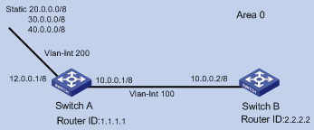
Networking and Configuration Requirements
l As shown in the figure above, Switch A and Switch B run OSPF. The router ID of Switch A is 1.1.1.1 and that of Switch B is 2.2.2.2.
l Configure three static routes and enable OSPF on Switch A.
l Apply a routing policy on Switch A when redistributing the three static routes so that the routes 20.0.0.0 and 40.0.0.0 are redistributed, and the route 30.0.0.0 is filtered out.
Applicable Product Matrix
|
Product series |
Software version |
Hardware version |
|
S3600-EI Series Ethernet switches |
Release 1510, Release1602 |
All versions |
|
S5600 Series Ethernet switches |
Release 1510, Release1602 |
All versions |
Configuration Procedure
Filter routing information with the import-route command and the route-policy command (method 1)
l Configure Switch A.
# Configure the IP addresses of the interfaces.
<SwitchA> system-view
[SwitchA] interface vlan-interface 100
[SwitchA-Vlan-interface100] ip address 10.0.0.1 255.0.0.0
[SwitchA-Vlan-interface100] quit
[SwitchA] interface vlan-interface 200
[SwitchA-Vlan-interface200] ip address 12.0.0.1 255.0.0.0
[SwitchA-Vlan-interface200] quit
# Configure three static routes.
[SwitchA] ip route-static 20.0.0.0 255.0.0.0 12.0.0.2
[SwitchA] ip route-static 30.0.0.0 255.0.0.0 12.0.0.2
[SwitchA] ip route-static 40.0.0.0 255.0.0.0 12.0.0.2
# Enable OSPF and specify VLAN-interface 10 to belong to area 0.
[SwitchA] router id 1.1.1.1
[SwitchA] ospf
[SwitchA-ospf-1] area 0
[SwitchA-ospf-1-area-0.0.0.0] network 10.0.0.0 0.255.255.255
[SwitchA-ospf-1-area-0.0.0.0] quit
[SwitchA-ospf-1]quit
# Configure an ACL.
[SwitchA] acl number 2000
[SwitchA-acl-basic-2000] rule deny source 30.0.0.0 0.255.255.255
[SwitchA-acl-basic-2000] rule permit source any
[SwitchA-acl-basic-2000] quit
# Configure a routing policy.
[SwitchA] route-policy ospf permit node 10
[SwitchA-route-policy] if-match acl 2000
[SwitchA-route-policy] quit
# Apply the routing policy when the static routes are redistributed.
[SwitchA] ospf
[SwitchA-ospf-1] import-route static route-policy ospf
l Configure Switch B.
# Configure the IP address of the interface.
<SwitchB> system-view
[SwitchB] interface vlan-interface 100
[SwitchB-Vlan-interface100] ip address 10.0.0.2 255.0.0.0
[SwitchB-Vlan-interface100] quit
# Enable OSPF and specify VLAN interface 100 to belong to area 0.
[SwitchB] router id 2.2.2.2
[SwitchB] ospf
[SwitchB-ospf-1] area 0
[SwitchB-ospf-1-area-0.0.0.0] network 10.0.0.0 0.255.255.255
[SwitchB-ospf-1-area-0.0.0.0] quit
[SwitchB-ospf-1] quit
Filter routing information with the import-route command and the filter-policy export command (method 2)
l Configure Switch A.
# Configure the IP addresses of the interfaces.
<SwitchA> system-view
[SwitchA] interface vlan-interface 100
[SwitchA-Vlan-interface100] ip address 10.0.0.1 255.0.0.0
[SwitchA-Vlan-interface100] quit
[SwitchA] interface vlan-interface 200
[SwitchA-Vlan-interface200] ip address 12.0.0.1 255.0.0.0
[SwitchA-Vlan-interface200] quit
# Configure three static routes.
[SwitchA] ip route-static 20.0.0.0 255.0.0.0 12.0.0.2
[SwitchA] ip route-static 30.0.0.0 255.0.0.0 12.0.0.2
[SwitchA] ip route-static 40.0.0.0 255.0.0.0 12.0.0.2
# Enable OSPF and specify VLAN interface 100 to belong to area 0.
[SwitchA] router id 1.1.1.1
[SwitchA] ospf
[SwitchA-ospf-1] area 0
[SwitchA-ospf-1-area-0.0.0.0] network 10.0.0.0 0.255.255.255
[SwitchA-ospf-1-area-0.0.0.0] quit
[SwitchA-ospf-1] quit
# Configure an ACL.
[SwitchA] acl number 2000
[SwitchA-acl-basic-2000] rule deny source 30.0.0.0 0.255.255.255
[SwitchA-acl-basic-2000] rule permit source any
[SwitchA-acl-basic-2000] quit
# Apply ACL 2000 to filter the advertised routes.
[SwitchA] ospf
[SwitchA-ospf-1] filter-policy 2000 export
# Redistribute static routes.
[SwitchA-ospf-1] import-route static
l Configure Switch B.
The configuration on Switch B is the same as that in method 1. Refer to the configuration on Switch B in Configuration Procedure.
Filter routing information with the import-route command and the asbr-summary not-advertise command (method 3)
l Configure Switch A.
# Configure the IP addresses of the interfaces.
<SwitchA> system-view
[SwitchA] interface vlan-interface 100
[SwitchA-Vlan-interface100] ip address 10.0.0.1 255.0.0.0
[SwitchA-Vlan-interface100] quit
[SwitchA] interface vlan-interface 200
[SwitchA-Vlan-interface200] ip address 12.0.0.1 255.0.0.0
[SwitchA-Vlan-interface200] quit
# Configure three static routes.
[SwitchA] ip route-static 20.0.0.0 255.0.0.0 12.0.0.2
[SwitchA] ip route-static 30.0.0.0 255.0.0.0 12.0.0.2
[SwitchA] ip route-static 40.0.0.0 255.0.0.0 12.0.0.2
# Enable OSPF and specify VLAN interface 100 to belong to area 0.
[SwitchA] router id 1.1.1.1
[SwitchA] ospf
[SwitchA-ospf-1] area 0
[SwitchA-ospf-1-area-0.0.0.0] network 10.0.0.0 0.255.255.255
[SwitchA-ospf-1-area-0.0.0.0] quit
# Configure route summarization to prevent network 30.0.0.0/8 from being advertised.
[SwitchA-ospf-1] asbr-summary 30.0.0.0 255.0.0.0 not-advertise
# Redistribute the static routes.
[SwitchA-ospf-1] import-route static
l Configure Switch B.
The configuration on Switch B is the same as that in method 1. Refer to the configuration on Switch B in Configuration Procedure.
Complete Configuration
In the following complete configuration, the import-route command and the route-policy command are used to filter routing information (method 1). For the complete configurations of other methods, refer to Configuration Procedure.
l Perform the following configuration on Switch A.
#
router id 1.1.1.1
#
acl number 2000
rule 0 deny source 30.0.0.0 0.255.255.255
rule 1 permit
#
vlan 100
#
vlan 200
#
interface Vlan-interface100
ip address 10.0.0.1 255.0.0.0
#
interface Vlan-interface200
ip address 12.0.0.1 255.0.0.0
#
ospf 1
import-route static route-policy ospf
area 0.0.0.0
network 10.0.0.0 0.255.255.255
#
route-policy ospf permit node 10
if-match acl 2000
#
ip route-static 20.0.0.0 255.0.0.0 12.0.0.2 preference 60
ip route-static 30.0.0.0 255.0.0.0 12.0.0.2 preference 60
ip route-static 40.0.0.0 255.0.0.0 12.0.0.2 preference 60
#
l Perform the following configuration on Switch B.
#
router id 2.2.2.2
#
vlan 100
#
interface Vlan-interface100
ip address 10.0.0.2 255.0.0.0
#
ospf 1
area 0.0.0.0
network 10.0.0.0 0.255.255.255
#
Precautions
In an OSPF network, when an ASBR redistributes routes, you can use the command combination of filter-policy export and import-route, route-policy and import-route, or import-route and asbr-summary not-advertise to filter redistributed routing information based on the actual conditions.