- Table of Contents
-
- H3C Low-End Ethernet Switches Configuration Guide(V1.01)
- 01-Login Configuration Guide
- 02-VLAN Configuration Guide
- 03-IP Address Configuration Guide
- 04-Voice VLAN Configuration Guide
- 05-GVRP Configuration Guide
- 06-Ethernet Interface Basic Configuration Guide
- 07-Link Aggregation Configuration Guide
- 08-Port Isolation Configuration Guide
- 09-Port Security Configuration Guide
- 10-Port Binding Configuration Guide
- 11-MAC Address Table Management Configuration Guide
- 12-DLDP Configuration Guide
- 13-Auto Detect Configuration Guide
- 14-MSTP Configuration Guide
- 15-Routing Configuration Guide
- 16-Multicast Configuration Guide
- 17-802.1x Configuration Guide
- 18-AAA Configuration Guide
- 19-MAC Authentication Configuration Guide
- 20-VRRP Configuration Guide
- 21-ARP Configuration Guide
- 22-DHCP Configuration Guide
- 23-ACL Configuration Guide
- 24-QoS-QoS Profile Configuration Guide
- 25-Web Cache Redirection Configuration Guide
- 26-Mirroring Configuration Guide
- 27-IRF Configuration Guide
- 28-Cluster Configuration Guide
- 29-PoE-PoE Profile Configuration Guide
- 30-UDP Helper Configuration Guide
- 31-SNMP-RMON Configuration Guide
- 32-NTP Configuration Guide
- 33-SSH Configuration Guide
- 34-FTP and TFTP Configuration Guide
- 35-Information Center Configuration Guide
- 36-VLAN-VPN Configuration Guide
- 37-HWPing Configuration Guide
- 38-DNS Configuration Guide
- 39-Access Management Configuration Guide
- 40-Web Authentication Configuration Guide
- 41-IPv6 Management Configuration Guide
- 42-Smart link - Monitor Link Configuration Guide
- 43-VLAN Mapping Configuration Guide
- Related Documents
-
| Title | Size | Download |
|---|---|---|
| 26-Mirroring Configuration Guide | 128.54 KB |
Local Port Mirroring Configuration
Networking and Configuration Requirements
Remote Port Mirroring Configuration
Networking and Configuration Requirements
Traffic Mirroring Configuration
Networking and Configuration Requirements
Local Port Mirroring Configuration
Network Diagram
Figure 1-1 Network diagram for local port mirroring
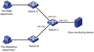
Networking and Configuration Requirements
The departments of a company connect to each other through S3600-EI Ethernet switches:
l Research and Development (R&D) department is connected to Switch C through Ethernet 1/0/1.
l Marketing department is connected to Switch C through Ethernet 1/0/2.
l Data monitoring device is connected to Switch C through Ethernet 1/0/3.
The administrator wants to monitor the packets received on and sent from the R&D department and the marketing department through the data monitoring device.
Use the local port mirroring function to meet the requirement. Perform the following configurations on Switch C.
l Configure Ethernet 1/0/1 and Ethernet 1/0/2 as mirroring source ports.
l Configure Ethernet 1/0/3 as the mirroring destination port.
Applicable Product Matrix
|
Product series |
Software version |
Hardware version |
|
S5600 series |
Release 1510, Release1602 |
All versions |
|
S5100-SI/EI series |
Release 2200, Release2201 |
All versions |
|
S3600-SI/EI series |
Release 1510, Release1602 |
All versions |
|
S3100-EI series |
Release 2104, Release 2107 |
All versions |
|
S3100-C-SI series S3100-T-SI series |
Release 0011, Release 2102, Release 2107 |
All versions |
|
S3100-52P |
Release 1500, Release 1602 |
S3100-52P |
Configuration Procedure
Configure Switch C:
# Create a local mirroring group.
<H3C> system-view
[H3C] mirroring-group 1 local
# Configure the source ports and destination port for the local mirroring group.
[H3C] mirroring-group 1 mirroring-port Ethernet 1/0/1 Ethernet 1/0/2 both
[H3C] mirroring-group 1 monitor-port Ethernet 1/0/3
Complete Configuration
#
mirroring-group 1 local
#
interface Ethernet1/0/1
mirroring-group 1 mirroring-port both
#
interface Ethernet1/0/2
mirroring-group 1 mirroring-port both
#
interface Ethernet1/0/3
mirroring-group 1 monitor-port
#
Precautions
When configuring local port mirroring, note the following:
l Packets sent from the switch CPU cannot be mirrored.
l Packets received on the destination port are those processed and forwarded by the switch.
l The local mirroring group takes effect only after a source port and a destination port are added to it.
l The source port or destination port to be configured cannot be a fabric port (only S3600/S5600 series Ethernet switches have this limitation), or a member port of an existing mirroring group; besides, a destination port cannot be a member port of an aggregation group, an LACP-enabled port, or an STP enabled port.
l When you configure a mirroring destination port on an S3600-EI series Ethernet switch, if mirroring group 1 does not exist on the switch, the switch will automatically create local mirroring group 1 and add the destination port to the group; if port mirroring group 1 already exists but is not a local mirroring group, your configuration of the destination port will fail.
l On an S3600-SI series Ethernet switch, if you execute the monitor-port command on different ports to configure the mirroring destination port for the switch, the last configuration takes effect.
Remote Port Mirroring Configuration
Remote port mirroring does not require the source and destination ports to be on the same device. The source and destination ports can be located on multiple devices across the network. Therefore, administrators can monitor the traffic on remote devices conveniently.
A special VLAN, called remote-probe VLAN, is needed to implement remote port mirroring. All mirrored packets are sent from the reflector port of the source switch to the monitor port (destination port) of the destination switch through the remote-probe VLAN, so that you can monitor packets received on and sent from the source switch on the destination switch. Figure 1-2illustrates the implementation of remote port mirroring.
Figure 1-2 Remote port mirroring application
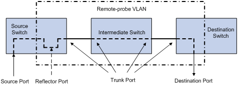
Switches involved in remote port mirroring play one of the following three roles:
l Source switch: The monitored port resident switch. It copies traffic to the reflector port, which then transmits the traffic to an intermediate switch or the destination switch through the remote-probe VLAN.
l Intermediate switch: Switches between the source switch and the destination switch on the network. An intermediate switch forwards mirrored traffic to the next intermediate switch or the destination switch through the remote-probe VLAN. No intermediate switch is present if the source switch and the destination switch are directly connected to each other.
Network Diagram
Figure 1-3 Network diagram for remote port mirroring
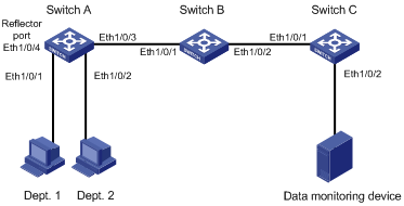
Networking and Configuration Requirements
The departments of a company connect to each other through S3600-EI Ethernet switches:
l Switch A, Switch B, and Switch C are S3600-EI series switches.
l Department 1 is connected to Ethernet 1/0/1 of Switch A.
l Department 2 is connected to Ethernet 1/0/2 of Switch A.
l Ethernet 1/0/3 of Switch A connects to Ethernet 1/0/1 of Switch B.
l Ethernet 1/0/2 of Switch B connects to Ethernet 1/0/1 of Switch C.
l Data monitoring device is connected to Ethernet 1/0/2 of Switch C.
The administrator wants to monitor the packets sent from Department 1 and 2 through the data monitoring device.
Use the remote port mirroring function to meet the requirement. Perform the following configurations:
l Use Switch A as the source switch, Switch B as the intermediate switch, and Switch C as the destination switch.
l On Switch A, create a remote source mirroring group, configure VLAN 10 as the remote-probe VLAN, ports Ethernet 1/0/1 and Ethernet 1/0/2 as the source ports, and port Ethernet 1/0/4 as the reflector port.
l On Switch B, configure VLAN 10 as the remote-probe VLAN.
l Configure Ethernet 1/0/3 of Switch A, Ethernet 1/0/1 and Ethernet 1/0/2 of Switch B, and Ethernet 1/0/1 of Switch C as Trunk ports, allowing packets of VLAN 10 to pass.
Applicable Product Matrix
|
Product series |
Software version |
Hardware version |
|
S5600 series |
Release 1510, Release1602 |
All versions |
|
S5100-SI/EI series |
Release 2200, Release2201 |
All versions |
|
S3600-EI series |
Release 1510, Release1602 |
All versions |
|
S3100-EI series |
Release 2104, Release 2107 |
All versions |
|
S3100-C-SI series S3100-T-SI series |
Release 0011, Release 2102, Release 2107 |
All versions |
|
S3100-52P |
Release 1500, Release 1602 |
S3100-52P |
Configuration Procedure
1) Configure the source switch (Switch A)
# Create remote source mirroring group 1.
<H3C> system-view
[H3C] mirroring-group 1 remote-source
# Configure VLAN 10 as the remote-probe VLAN.
[H3C] vlan 10
[H3C-vlan10] remote-probe vlan enable
[H3C-vlan10] quit
# Configure the source ports, reflector port, and remote-probe VLAN for the remote source mirroring group.
[H3C] mirroring-group 1 mirroring-port Ethernet 1/0/1 Ethernet 1/0/2 inbound
[H3C] mirroring-group 1 reflector-port Ethernet 1/0/4
[H3C] mirroring-group 1 remote-probe vlan 10
# Configure Ethernet 1/0/3 as a Trunk port, allowing packets of VLAN 10 to pass.
[H3C] interface Ethernet 1/0/3
[H3C-Ethernet1/0/3] port link-type trunk
[H3C-Ethernet1/0/3] port trunk permit vlan 10
2) Configure the intermediate switch (Switch B)
# Configure VLAN 10 as the remote-probe VLAN.
<H3C> system-view
[H3C] vlan 10
[H3C-vlan10] remote-probe vlan enable
[H3C-vlan10] quit
# Configure Ethernet 1/0/1 as a Trunk port, allowing packets of VLAN 10 to pass.
[H3C] interface Ethernet 1/0/1
[H3C-Ethernet1/0/1] port link-type trunk
[H3C-Ethernet1/0/1] port trunk permit vlan 10
# Configure Ethernet 1/0/2 as a Trunk port, allowing packets of VLAN 10 to pass.
[H3C] interface Ethernet 1/0/2
[H3C-Ethernet1/0/2] port link-type trunk
[H3C-Ethernet1/0/2] port trunk permit vlan 10
3) Configure the destination switch (Switch C)
# Create remote destination mirroring group 1.
<H3C> system-view
[H3C] mirroring-group 1 remote-destination
# Configure VLAN 10 as the remote-probe VLAN.
[H3C] vlan 10
[H3C-vlan10] remote-probe vlan enable
[H3C-vlan10] quit
# Configure the destination port and remote-probe VLAN for the remote destination mirroring group.
[H3C] mirroring-group 1 monitor-port Ethernet 1/0/2
[H3C] mirroring-group 1 remote-probe vlan 10
# Configure Ethernet 1/0/1 as a Trunk port, allowing packets of VLAN 10 to pass.
[H3C] interface Ethernet 1/0/1
[H3C-Ethernet1/0/1] port link-type trunk
[H3C-Ethernet1/0/1] port trunk permit vlan 10
Complete Configuration
1) Configuration on the source switch (Switch A)
#
mirroring-group 1 remote-source
#
vlan 10
remote-probe vlan enable
#
interface Ethernet1/0/1
mirroring-group 1 mirroring-port inbound
#
interface Ethernet1/0/2
mirroring-group 1 mirroring-port inbound
#
interface Ethernet1/0/3
port link-type trunk
port trunk permit vlan 1 10
#
interface Ethernet1/0/4
duplex full
speed 100
mirroring-group 1 reflector-port
#
mirroring-group 1 remote-probe vlan 10
#
2) Configuration on the intermediate switch (Switch B)
#
vlan 10
remote-probe vlan enable
#
interface Ethernet1/0/1
port link-type trunk
port trunk permit vlan 1 10
#
interface Ethernet1/0/2
port link-type trunk
port trunk permit vlan 1 10
#
3) Configuration on the destination switch (Switch C)
#
mirroring-group 1 remote-destination
#
vlan 10
remote-probe vlan enable
#
interface Ethernet1/0/1
port link-type trunk
port trunk permit vlan 1 10
#
interface Ethernet1/0/2
port access vlan 10
mirroring-group 1 monitor-port
#
Precautions
Note the following when configuring the source switch:
l All ports in a remote source mirroring group are on the same switch (the source switch). A remote source mirroring group can have only one reflector port.
l The reflector port of a mirroring group cannot be a member port of another existing mirroring group, a fabric port (only the S3600/S5600 series Ethernet switches have this limitation), a member port of an aggregation group, or a port enabled with LACP or STP. It must be an Access port and cannot be configured with functions like VLAN-VPN, port loopback detection, packet filtering, QoS, port security, and so on.
l You cannot modify the duplex mode, port rate, and MDI attribute of a reflector port.
l For mirroring to function properly, do not configure VLAN mapping or selective QinQ on a reflector port.
l Only an existing static VLAN can be configured as the remote-probe VLAN. To remove a remote-probe VLAN, you need to restore it to a normal VLAN first. A remote port mirroring group gets invalid if the corresponding remote-probe VLAN is removed.
l Do not configure the default VLAN, management VLAN or dynamic VLAN as the remote-probe VLAN.
l Configure all ports connecting the devices in the remote-probe VLAN as Trunk ports, and ensure the Layer 2 connectivity from the source switch to the destination switch over the remote-probe VLAN.
l Do not configure a Layer 3 interface for the remote-probe VLAN, run other protocol packets, or carry other service packets on the remote-prove VLAN and do not use the remote-prove VLAN as the voice VLAN and protocol-based VLAN; otherwise, remote port mirroring may be affected.
l Do not configure a port connecting the intermediate switch or destination switch as the mirroring source port. Otherwise, traffic disorder may occur in the network.
l If the intermediate or destination switch is an S3600-EI/S5600, the bidirectional mirroring (the both keyword) function is not available.
l The S3100-SI series Ethernet switches do not support the both keyword configuration.
Note the following when configuring the destination switch:
l Packets sent from the switch CPU cannot be mirrored.
l Packets received on the destination port are those processed and forwarded by the switch.
l The destination port to be configured cannot be a member port of an existing mirroring group; a fabric port (only the S3600/S5600 series Ethernet switches have this limitation), a member port of an aggregation group, an LACP enabled port, or an STP enabled port.
l Only an existing static VLAN can be configured as the remote-probe VLAN. To remove a remote-probe VLAN, you need to restore it to a normal VLAN first. A remote port mirroring group gets invalid if the corresponding remote-probe VLAN is removed.
Traffic Mirroring Configuration
Network Diagram
Figure 1-4 Network diagram for traffic mirroring
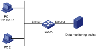
Networking and Configuration Requirements
The departments of a company connect to each other through S3600 series Ethernet switches:
l PC 1 and PC 2 are connected to Switch through Ethernet 1/0/1. The IP address of PC 1 is 192.168.0.1.
l Data monitoring device is connected to Ethernet 1/0/2 of Switch.
The administrator wants to monitor packets sent from PC 1 through the data monitoring device.
Use the traffic mirroring function to meet the requirement. Perform the following configurations on Switch:
l Configure traffic mirroring on Ethernet 1/0/1. Mirror packets matching source IP address 192.168.0.1 to the destination port.
l Configure Ethernet 1/0/2 as the destination port of traffic mirroring.
Applicable Product Matrix
|
Product series |
Software version |
Hardware version |
|
S5600 series |
Release 1510, Release1602 |
All versions |
|
S5100-EI series |
Release 2200, Release2201 |
All versions |
|
S3600-SI/EI series |
Release 1510, Release1602 |
All versions |
|
S3100-EI series |
Release 2104, Release 2107 |
All versions |
|
S3100-52P |
Release 1500, Release 1602 |
S3100-52P |
Configuration Procedure
# Configure a basic ACL 2000, matching the packets whose source IP address is 192.168.0.1.
<H3C> system-view
[H3C] acl number 2000
[H3C-acl-basic-2000] rule permit source 192.168.0.1 0
[H3C-acl-basic-2000] quit
# Configure traffic mirroring on Ethernet 1/0/1. Mirror packets matching source IP address 192.168.0.1 to the destination port.
[H3C] interface Ethernet 1/0/1
[H3C-Ethernet1/0/1] mirrored-to inbound ip-group 2000 monitor-interface
[H3C-Ethernet1/0/1] quit
# Configure Ethernet 1/0/2 as the destination port of traffic mirroring.
[H3C] interface Ethernet 1/0/2
[H3C-Ethernet1/0/2] monitor-port
Complete Configuration
#
mirroring-group 1 local
#
acl number 2000
rule 0 permit source 192.168.0.1 0
#
interface Ethernet1/0/1
mirrored-to inbound ip-group 2000 rule 0 monitor-interface
#
interface Ethernet1/0/2
mirroring-group 1 monitor-port
#
Precautions
Note the following when configuring traffic mirroring:
l The destination port to be configured cannot be a member port of an existing mirroring group, a fabric port (only the S3600/S5600 series Ethernet switches have this limitation), a member port of an aggregation group, an LACP enabled port, or an STP enabled port.
l When you configure the destination port of traffic mirroring on an S3600-EI series Ethernet switch, if mirroring group 1 does not exist on the switch, the switch will automatically create local mirroring group 1 and add the destination port to the group; if mirroring group 1 already exists but is not a local mirroring group, your configuration of the destination port will fail.