- Table of Contents
-
- H3C Low-End Ethernet Switches Configuration Guide(V1.01)
- 01-Login Configuration Guide
- 02-VLAN Configuration Guide
- 03-IP Address Configuration Guide
- 04-Voice VLAN Configuration Guide
- 05-GVRP Configuration Guide
- 06-Ethernet Interface Basic Configuration Guide
- 07-Link Aggregation Configuration Guide
- 08-Port Isolation Configuration Guide
- 09-Port Security Configuration Guide
- 10-Port Binding Configuration Guide
- 11-MAC Address Table Management Configuration Guide
- 12-DLDP Configuration Guide
- 13-Auto Detect Configuration Guide
- 14-MSTP Configuration Guide
- 15-Routing Configuration Guide
- 16-Multicast Configuration Guide
- 17-802.1x Configuration Guide
- 18-AAA Configuration Guide
- 19-MAC Authentication Configuration Guide
- 20-VRRP Configuration Guide
- 21-ARP Configuration Guide
- 22-DHCP Configuration Guide
- 23-ACL Configuration Guide
- 24-QoS-QoS Profile Configuration Guide
- 25-Web Cache Redirection Configuration Guide
- 26-Mirroring Configuration Guide
- 27-IRF Configuration Guide
- 28-Cluster Configuration Guide
- 29-PoE-PoE Profile Configuration Guide
- 30-UDP Helper Configuration Guide
- 31-SNMP-RMON Configuration Guide
- 32-NTP Configuration Guide
- 33-SSH Configuration Guide
- 34-FTP and TFTP Configuration Guide
- 35-Information Center Configuration Guide
- 36-VLAN-VPN Configuration Guide
- 37-HWPing Configuration Guide
- 38-DNS Configuration Guide
- 39-Access Management Configuration Guide
- 40-Web Authentication Configuration Guide
- 41-IPv6 Management Configuration Guide
- 42-Smart link - Monitor Link Configuration Guide
- 43-VLAN Mapping Configuration Guide
- Related Documents
-
| Title | Size | Download |
|---|---|---|
| 16-Multicast Configuration Guide | 352.24 KB |
1 Multicast Configuration Guide·
Networking and Configuration Requirements
Configuring IGMP Snooping Only
Networking and Configuration Requirements
Networking and Configuration Requirements
Configuring PIM-SM plus IGMP plus IGMP Snooping
Networking and Configuration Requirements
Networking and Configuration Requirements
Configuring Anycast RP Application
Networking and Configuration Requirements
Configuring IGMP Snooping
Internet Group Management Protocol Snooping (IGMP Snooping) is a multicast constraint mechanism that runs on access switches to manage and control multicast groups to prevent multicast data from being flooded at the data link layer.
Network Diagram
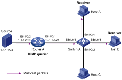
Figure 1-1 Network diagram for IGMP Snooping
Networking and Configuration Requirements
l As shown in Figure 1-1, Router A connects to a multicast source (Source) through Ethernet 1/0/2, and to Switch A through Ethernet 1/0/1.
l Run PIM DM and IGMP on Router A. Enable IGMP Snooping on Switch A. Router A is the IGMP querier.
Application Product Matrix
|
Product series |
Software version |
Hardware version |
|
S5600 series |
Release 1510, Release1602 |
All versions |
|
S5100-SI/EI series |
Release 2200, Release2201 |
All versions |
|
S3600-SI/EI series |
Release 1510, Release1602 |
All versions |
|
S3100-EI series |
Release 2104, Release 2107 |
All versions |
|
S3100-C-SI series S3100-T-SI series |
Release 0011, Release 2102, Release 2107 |
All versions |
|
S3100-52P |
Release 1500, Release 1602 |
S3100-52P |
Configuration Procedure
Configuring IP addresses for the interfaces of each device
Configure the IP address and subnet mask for each interface as per Figure 1-1. The detailed configuration steps are omitted here.
Configuring Router A
# Enable IP multicast routing, enable PIM-DM on each interface, and enable IGMP on Ethernet 1/0/1.
<RouterA> system-view
[RouterA] multicast routing-enable
[RouterA] interface Ethernet 1/0/1
[RouterA-Ethernet1/0/1] igmp enable
[RouterA-Ethernet1/0/1] pim dm
[RouterA-Ethernet1/0/1] quit
[RouterA] interface Ethernet 1/0/2
[RouterA-Ethernet1/0/2] pim dm
[RouterA-Ethernet1/0/2] quit
Configuring Switch A
# Enable IGMP Snooping globally.
<SwitchA> system-view
[SwitchA] igmp-snooping enable
Enable IGMP-Snooping ok.
# Create VLAN 100, assign Ethernet 1/0/1 through Ethernet 1/0/4 to VLAN 100, and enable IGMP Snooping in this VLAN.
[SwitchA] vlan 100
[SwitchA-vlan100] port Ethernet 1/0/1 to Ethernet 1/0/4
[SwitchA-vlan100] igmp-snooping enable
[SwitchA-vlan100] quit
Verifying the configuration
# View the multicast groups in VLAN 100 on Switch A.
<SwitchA> display igmp-snooping group vlan100
Total 1 IP Group(s).
Total 1 MAC Group(s).
Vlan(id):100.
Total 1 IP Group(s).
Total 1 MAC Group(s).
Router port(s):
Ethernet1/0/1
IP group(s):the following ip group(s) match to one mac group.
IP group address: 224.1.1.1
Host port(s):
Ethernet1/0/3 Ethernet1/0/4
MAC group(s):
MAC group address: 0100-5e01-0101
Host port(s): Ethernet1/0/3 Ethernet1/0/4
Complete Configuration
Configuration on Switch A
#
igmp-snooping enable
#
vlan 100
igmp-snooping enable
#
interface Ethernet1/0/1
port access vlan 100
#
interface Ethernet1/0/2
port access vlan 100
#
interface Ethernet1/0/3
port access vlan 100
#
interface Ethernet1/0/4
port access vlan 100
#
Precautions
l Layer 2 and Layer 3 multicast protocols can run on the same switch. However, a Layer 2 multicast protocol cannot run in a VLAN while a Layer 3 multicast protocol is running on the corresponding VLAN interface, and vice versa.
Configuring IGMP Snooping Only
Network Diagram
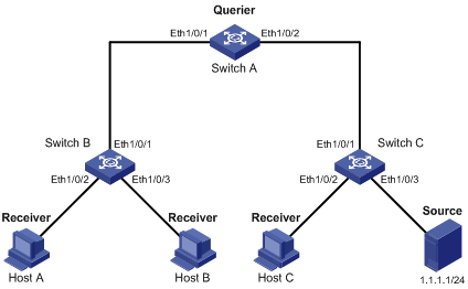
Figure 1-2 Network diagram for IGMP Snooping only configuration
Networking and Configuration Requirements
Where it is unnecessary or infeasible to build a Layer 3 multicast network, enabling IGMP Snooping on all the devices in the Layer 2 network can implement some multicast functions.
1) As shown in Figure 1-2, in a Layer 2 only network, Switch C connects to the multicast source through Ethernet 1/0/3. At least one receiver is attached to Switch B and Switch C respectively.
2) Enable IGMP Snooping on Switch A, Switch B, and Switch C. Switch A acts as the IGMP Snooping querier.
Application Product Matrix
|
Product series |
Software version |
Hardware version |
|
S5600 series |
Release 1510, Release1602 |
All versions |
|
S5100-SI/EI series |
Release 2200, Release2201 |
All versions |
|
S3600-SI/EI series |
Release 1510, Release1602 |
All versions |
|
S3100-EI series |
Release 2104, Release 2107 |
All versions |
|
S3100-C-SI series S3100-T-SI series |
Release 0011, Release 2102, Release 2107 |
All versions |
|
S3100-52P |
Release 1500, Release 1602 |
S3100-52P |
Configuration Procedure
Configuring Switch A
# Enable IGMP Snooping globally.
<SwitchA> system-view
[SwitchA] igmp-snooping enable
Enable IGMP-Snooping ok.
# Create VLAN 100, assign Ethernet 1/0/1 through Ethernet 1/0/2 to VLAN 100, and enable IGMP Snooping in this VLAN.
[SwitchA] vlan 100
[SwitchA-vlan100] port Ethernet 1/0/1 Ethernet 1/0/2
[SwitchA-vlan100] igmp-snooping enable
# Enable IGMP Snooping querier in VLAN 100.
[SwitchA-vlan100] igmp-snooping querier
[SwitchA-vlan100] quit
# Enable dropping unknown multicast packets.
[SwitchA] unknown-multicast drop enable
Configuring Switch B
# Enable IGMP Snooping globally.
<SwitchB> system-view
[SwitchB] igmp-snooping enable
Enable IGMP-Snooping ok.
# Create VLAN 100, assign Ethernet 1/0/1 through Ethernet 1/0/3 to VLAN 100, and enable IGMP Snooping in this VLAN.
[SwitchB] vlan 100
[SwitchB-vlan100] port Ethernet 1/0/1 to Ethernet 1/0/3
[SwitchB-vlan100] igmp-snooping enable
[SwitchB-vlan100] quit
# Enable dropping unknown multicast packets.
[SwitchB] unknown-multicast drop enable
Configuring Switch C
# Enable IGMP Snooping globally.
<SwitchC system-view
[SwitchC] igmp-snooping enable
Enable IGMP-Snooping ok.
# Create VLAN 100, assign Ethernet 1/0/1 through Ethernet 1/0/3 to VLAN 100, and enable IGMP Snooping in this VLAN.
[SwitchC] vlan 100
[SwitchC-vlan100] port Ethernet 1/0/1 to Ethernet 1/0/3
[SwitchC-vlan100] igmp-snooping enable
![]()
As Switch C is not the IGMP Snooping querier, it cannot create forwarding entries for Host A and Host B, and therefore, do not enable the function of dropping unknown multicast packets on Switch C. To avoid impact on the network and on Switch C caused by multicast flooding, it is recommended to enable IGMP Snooping querier on the switch to which the multicast source is directly attached.
Verifying the configuration
Check the reception of multicast stream for multicast group 224.1.1.1 on Host A, and take the following steps to verify the configurations made on the switches.
1) View the information on Switch B
# View the IGMP packet statistics on Switch B.
<SwitchB> display igmp-snooping statistics
Received IGMP general query packet(s) number:16.
Received IGMP specific query packet(s) number:3.
Received IGMP V1 report packet(s) number:0.
Received IGMP V2 report packet(s) number:53.
Received IGMP leave packet(s) number:1.
Received error IGMP packet(s) number:0.
Sent IGMP specific query packet(s) number:1.
Switch B has received IGMP general queries from the querier and IGMP reports from receivers.
# View the multicast group information on Switch B.
<Switch B> display igmp-snooping group
Total 1 IP Group(s).
Total 1 MAC Group(s).
Vlan(id):100.
Total 1 IP Group(s).
Total 1 MAC Group(s).
Router port(s):Ethernet1/0/1
IP group(s):the following ip group(s) match to one mac group.
IP group address:224.1.1.1
Host port(s):Ethernet1/0/2
MAC group(s):
MAC group address:0100-5e7f-fffe
Host port(s):Ethernet1/0/2
As shown above, a multicast group entry for the multicast group 224.1.1.1 has been created on Switch B, with Ethernet 1/0/1 as the dynamic router port and Ethernet 1/0/2 as the dynamic member port.
2) View the information on Switch A
# View the IGMP packet statistics on Switch A.
<SwitchA> display igmp-snooping statistics
Received IGMP general query packet(s) number:0.
Received IGMP specific query packet(s) number:0.
Received IGMP V1 report packet(s) number:0.
Received IGMP V2 report packet(s) number:53.
Received IGMP leave packet(s) number:1.
Received error IGMP packet(s) number:0.
Sent IGMP specific query packet(s) number:1.
Switch A receives IGMP reports from the receivers.
# View the multicast group information on Switch A.
<Switch A> display igmp-snooping group
Total 1 IP Group(s).
Total 1 MAC Group(s).
Vlan(id):100.
Total 1 IP Group(s).
Total 1 MAC Group(s).
Router port(s):
IP group(s):the following ip group(s) match to one mac group.
IP group address:224.1.1.1
Host port(s):Ethernet1/0/1
MAC group(s):
MAC group address:0100-5e7f-fffe
Host port(s):Ethernet1/0/1
As shown above, a multicast group entry for the multicast group 224.1.1.1 has been created on Switch A, with Ethernet 1/0/1 as the dynamic member port. Acting as the IGMP Snooping querier, Switch A does not have a router port.
3) View the information on Switch C
# View the IGMP packet statistics on Switch C.
<SwitchC> display igmp-snooping statistics
Received IGMP general query packet(s) number:10.
Received IGMP specific query packet(s) number:0.
Received IGMP V1 report packet(s) number:0.
Received IGMP V2 report packet(s) number:0.
Received IGMP leave packet(s) number:.0
Received error IGMP packet(s) number:0.
Sent IGMP specific query packet(s) number:0.
Switch C received only IGMP general queries from the querier.
# View the multicast group information on Switch C.
<Switch C> display igmp-snooping group
Total 0 IP Group(s).
Total 0 MAC Group(s).
Vlan(id):100.
Total 0 IP Group(s).
Total 0 MAC Group(s).
Router port(s):Ethernet1/0/1
Complete Configuration
Configuration on Switch A
#
unknown-multicast drop enable
#
igmp-snooping enable
#
vlan 100
igmp-snooping enable
igmp-snooping querier
#
interface Ethernet1/0/1
port access vlan 100
#
interface Ethernet1/0/2
port access vlan 100
#
Configuration on Switch B
#
unknown-multicast drop enable
#
igmp-snooping enable
#
vlan 100
igmp-snooping enable
#
interface Ethernet1/0/1
port access vlan 100
#
interface Ethernet1/0/2
port access vlan 100
#
interface Ethernet1/0/3
port access vlan 100
#
Configuration on Switch C
#
igmp-snooping enable
#
vlan 100
igmp-snooping enable
#
interface Ethernet1/0/1
port access vlan 100
#
interface Ethernet1/0/2
port access vlan 100
#
interface Ethernet1/0/3
port access vlan 100
#
Configuring Multicast VLAN
In the traditional multicast-on-demand mode, when users in different VLANs on a Layer 2 device need multicast information, the multicast router needs to forward a separate copy of the multicast data to each of these VLANs. This mode wastes a great deal of bandwidth.
Network Diagram
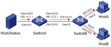
Figure 1-3 Network diagram for multicast VLAN
Networking and Configuration Requirements
Configure the multicast VLAN feature so that Switch A just sends multicast data to VLAN 10 rather than to each VLAN when Host A and Host B attached to Switch B need the multicast data.
The following table describes the device details:
|
Device |
Description |
Remarks |
|
Switch A |
Layer 3 switch |
IP address of VLAN-interface 20 is 168.10.1.1. Ethernet 1/0/1 belongs to VLAN 20 and is connected with the workstation. IP address of VLAN-interface 10 is 168.10.2.1. Ethernet 1/0/10 belongs to VLAN 10 and is connected with Switch B. |
|
Switch B |
Layer 2 switch |
VLAN 2 contains Ethernet 1/0/1 and VLAN 3 contains Ethernet 1/0/2. These two ports are connected with Host A and Host B respectively. The default VLAN of Ethernet 1/0/1 is VLAN 2 and the default VLAN of Ethernet 1/0/2 is VLAN 3. VLAN 10 contains Ethernet 1/0/10, Ethernet 1/0/1 and Ethernet 1/0/2. Ethernet 1/0/10 is connected with Switch A. VLAN 10 is multicast VLAN. Ethernet 1/0/1 sends packets of VLAN 2 and VLAN 10 without VLAN tags. Ethernet 1/0/2 sends packets of VLAN 3 and VLAN 10 without VLAN tags. |
|
HostA |
User 1 |
Connected with Ethernet 1/0/1 of Switch B |
|
HostB |
User 2 |
Connected with Ethernet 1/0/2 of Switch B |
Application Product Matrix
|
Product series |
Software version |
Hardware version |
|
S5600 series |
Release 1510, Release1602 |
All versions |
|
S5100-SI/EI series |
Release 2200, Release2201 |
All versions |
|
S3600-SI/EI series |
Release 1510, Release1602 |
All versions |
|
S3100-EI series |
Release 2104, Release 2107 |
All versions |
|
S3100-C-SI series S3100-T-SI series |
Release 0011, Release 2102, Release 2107 |
All versions |
|
S3100-52P |
Release 1500, Release 1602 |
S3100-52P |
Configuration Procedure
Assume that the IP addresses have been configured and the devices have been connected correctly.
1) Configure Switch A.
# Configure the IP address of VLAN-interface 20 as 168.10.1.1, and enable PIM-DM.
<SwitchA> system-view
[SwitchA] multicast routing-enable
[SwitchA] vlan 20
[SwitchA–vlan20]port Ethernet1/0/1
[SwitchA-vlan20] quit
[SwitchA] interface Vlan-interface 20
[SwitchA-Vlan-interface20] ip address 168.10.1.1 255.255.255.0
[SwitchA-Vlan-interface20] pim dm
[SwitchA-Vlan-interface20] quit
# Create VLAN 10.
[SwitchA] vlan 10
[SwitchA-vlan10] quit
# Configure Ethernet 1/0/10 as a Hybrid port, assign it to VLAN 10, and configure it to send packets of VLAN 10 with the VLAN tag kept.
[SwitchA] interface Ethernet1/0/10
[SwitchA-Ethernet1/0/10] port link-type hybrid
[SwitchA-Ethernet1/0/10] port hybrid vlan 10 tagged
[SwitchA-Ethernet1/0/10] quit
# Configure the IP address of VLAN-interface 10 as 168.10.2.1, and enable PIM-DM and IGMP.
[SwitchA] interface Vlan-interface 10
[SwitchA-Vlan-interface10] ip address 168.10.2.1 255.255.255.0
[SwitchA-Vlan-interface10] igmp enable
[SwitchA-Vlan-interface10] pim dm
2) Configure Switch B.
# Enable IGMP Snooping globally.
<SwitchB> system-view
[SwitchB] igmp-snooping enable
# Create VLAN 2, VLAN 3, and VLAN 10, configure VLAN 10 as a multicast VLAN, and enable IGMP Snooping in VLAN 10.
[SwitchB] vlan 2 to 3
Please wait.... Done.
[SwitchB] vlan 10
[SwitchB-vlan10] service-type multicast
[SwitchB-vlan10] igmp-snooping enable
[SwitchB-vlan10] quit
# Configure Ethernet 1/0/10 as a Hybrid port, assign it to VLAN 2, VLAN 3 and VLAN 10, and configure it to send packets of VLAN 2, VLAN 3, and VLAN 10 with the respective VLAN tags kept.
[SwitchB] interface Ethernet1/0/10
[SwitchB-Ethernet1/0/10] port link-type hybrid
[SwitchB-Ethernet1/0/10] port hybrid vlan 2 3 10 tagged
[SwitchB-Ethernet1/0/10] quit
# Configure Ethernet 1/0/1 as a Hybrid port, assign it to VLAN 2 and VLAN 10, and configure it to send packets of VLAN 2 and VLAN 10 without VLAN tags. Configure VLAN 2 as the default VLAN.
[SwitchB] interface Ethernet1/0/1
[SwitchB-Ethernet1/0/1] port link-type hybrid
[SwitchB-Ethernet1/0/1] port hybrid vlan 2 10 untagged
[SwitchB-Ethernet1/0/1] port hybrid pvid vlan 2
[SwitchB-Ethernet1/0/1] quit
# Configure Ethernet 1/0/2 as a Hybrid port, assign it to VLAN 3 and VLAN 10, and configure it to send packets of VLAN 3 and VLAN 10 without VLAN tags. Configure VLAN 3 as the default VLAN.
[SwitchB] interface Ethernet1/0/2
[SwitchB-Ethernet1/0/2] port link-type hybrid
[SwitchB-Ethernet1/0/2] port hybrid vlan 3 10 untagged
[SwitchB-Ethernet1/0/2] port hybrid pvid vlan 3
[SwitchB-Ethernet1/0/2] quit
Complete Configuration
Configuration on Switch A
#
multicast routing-enable
#
interface Vlan-interface10
ip address 168.10.2.1 255.255.255.0
igmp enable
pim dm
#
interface Vlan-interface20
ip address 168.10.1.1 255.255.255.0
pim dm
#
interface Ethernet1/0/1
port access vlan 20
#
interface Ethernet1/0/10
port link-type hybrid
port hybrid vlan 10 tagged
#
Configuration on Switch B
#
igmp-snooping enable
#
vlan 1 to 3
#
vlan 10
service-type multicast
igmp-snooping enable
#
interface Ethernet1/0/1
port link-type hybrid
port hybrid vlan 1 to 2 10 untagged
port hybrid pvid vlan 2
#
interface Ethernet1/0/2
port link-type hybrid
port hybrid vlan 1 3 10 untagged
port hybrid pvid vlan 3
#
interface Ethernet1/0/10
port link-type hybrid
port hybrid vlan 2 to 3 10 tagged
port hybrid vlan 1 untagged
Precautions
l A port belongs to one multicast VLAN only.
l Only Hybrid ports can be connected with receivers.
l Upon receiving a multicast packet, a router port forwards the packet only to the member ports in the same VLAN. Therefore, the member ports must belong to the same multicast VLAN with the router port.
l When assigning a router port to a multicast VLAN, be sure to configure it as a trunk port, or a hybrid port that sends packets of the multicast VLAN with the VLAN tag kept; otherwise all the member ports in this multicast VLAN will be unable to receive multicast packets.
Configuring PIM-SM plus IGMP plus IGMP Snooping
PIM-SM is a type of sparse mode multicast protocol. It uses the “pull mode” for multicast forwarding, and is suitable for large- and medium-sized networks with sparsely and widely distributed multicast group members.
The basic implementation of PIM-SM is as follows:
l PIM-SM assumes that hosts need multicast data only if they explicitly express their interest in the data. PIM-SM builds and maintains rendezvous point trees (RPT) for multicast traffic delivery. An RPT is rooted at a router in the PIM domain as the common node referred to as rendezvous point (RP), through which the multicast data travels along the RPT and reaches the receivers.
l When a receiver is interested in the multicast data addressed to a specific multicast group, the last-hop router sends a join message to the RP corresponding to that multicast group. The path along which the message goes hop by hop to the RP forms a branch of the RPT.
l When a multicast source sends multicast traffic to a multicast group, the first-hop router encapsulates the first packet in a register message, and sends the message to the corresponding RP by unicast. The arrival of this message at the RP triggers the establishment of an SPT rooted at the multicast source. Then, the multicast source sends the multicast traffic along the SPT to the RP. Upon reaching the RP, the multicast traffic flows down the RPT to the receivers.
Network Diagram
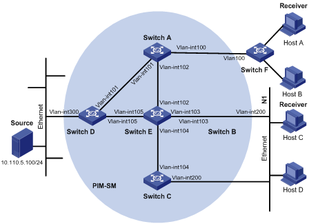
Figure 1-4 Network diagram for PIM-SM, IGMP, and IGMP Snooping configuration
|
Device |
Interface |
IP address |
Ports |
|
Switch A |
Vlan-int100 |
10.110.1.1/24 |
Ethernet1/0/1 |
|
|
Vlan-int101 |
192.168.1.1/24 |
Ethernet1/0/2 |
|
|
Vlan-int102 |
192.168.9.1/24 |
Ethernet1/0/3 |
|
Switch B |
Vlan-int200 |
10.110.2.1/24 |
Ethernet1/0/1 |
|
|
Vlan-int103 |
192.168.2.1/24 |
Ethernet1/0/2 |
|
Switch C |
Vlan-int200 |
10.110.2.2/24 |
Ethernet1/0/1 |
|
|
Vlan-int104 |
192.168.3.1/24 |
Ethernet1/0/2 |
|
Switch D |
Vlanint300 |
10.110.5.1/24 |
Ethernet1/0/1 |
|
|
Vlanint101 |
192.168.1.2/24 |
Ethernet1/0/2 |
|
|
Vlanint105 |
192.168.4.2/24 |
Ethernet1/0/3 |
|
Switch E |
Vlanint104 |
192.168.3.2/24 |
Ethernet1/0/3 |
|
|
Vlanint103 |
192.168.2.2/24 |
Ethernet1/0/2 |
|
|
Vlanint102 |
192.168.9.2/24 |
Ethernet1/0/1 |
|
|
Vlanint105 |
192.168.4.1/24 |
Ethernet1/0/4 |
|
Switch F |
Vlan100 |
- |
Ethernet1/0/1, Ethernet1/0/2, Ethernet1/0/3 |
Networking and Configuration Requirements
Requirement Analysis
When users receive VOD information through multicast, the information receiving mode may vary depending on user requirements:
1) To avoid flooding of the video information at Layer 2, IGMP Snooping needs to be enabled on Switch E, through which Host A and Host B receive the multicast data.
2) To ensure reliable and stable reception of multicast data, Switch B and Switch C provide link backup for the directly attached stub network N1, which comprises multicast receivers Host C and Host D.
3) The PIM-SM domain as a single-BSR domain, and OSPF runs in the domain for unicast routing.
Configuration Plan
1) Switch D connects to the network that comprises the multicast source (Source) through VLAN-interface 300.
2) Switch A connects to Switch F through VLAN-interface 100, and to Switch D and Switch E through VLAN-interface 101 and VLAN-interface 102 respectively.
3) Switch B and Switch C connect to stub network N1 through their respective VLAN-interface 200, and to Switch E through VLAN-interface 103 and VLAN-interface 104 respectively.
4) Both VLAN-interface 105 of Switch D and VLAN-interface 102 of Switch E serve as C-BSRs and C-RPs.
Application Product Matrix
|
Product series |
Software version |
Hardware version |
|
S3600-EI series |
Release 1510, Release 1602 |
All versions |
|
S5600 series |
Release 1510, Release 1602 |
All versions |
Configuration Procedure
Configuring the interface IP addresses and unicast routing protocol for each switch
Configure the IP address and subnet mask for each interface as per Figure 1-4. The detailed configuration steps are omitted here.
Configure OSPF for interoperation among the switches in the PIM-SM domain. Ensure the network-layer interoperation among Switch A, Switch B, Switch C, Switch D and Switch E in the PIM-SM domain and enable dynamic update of routing information among the switches through a unicast routing protocol. The specific configuration steps are omitted here.
Configuring multicast protocols
# Enable IP multicast routing on Switch A, enable PIM-SM on each interface, and run IGMPv2 on VLAN-interface 100.
<SwitchA> system-view
[SwitchA] multicast routing-enable
[SwitchA] interface Vlan-interface 100
[SwitchA-Vlan-interface100] igmp enable
[SwitchA-Vlan-interface100] pim sm
[SwitchA-Vlan-interface100] quit
[SwitchA] interface vlan-interface 101
[SwitchA-Vlan-interface101] pim sm
[SwitchA-Vlan-interface101] quit
[SwitchA] interface vlan-interface 102
[SwitchA-Vlan-interface102] pim sm
![]()
It is necessary to enable IGMP only on interfaces with multicast receivers attached. The default IGMP version is IGMPv2.
The configuration on Switch B and Switch C is similar to that on Switch A. The configuration on Switch D and Switch E is also similar to that on Switch A except that it is not necessary to enable IGMP on the corresponding interfaces on these two switches.
# Configure the group range to be advertised in C-RP-Adv messages and configure a C-BSR and a C-RP on VLAN-interface 105 of Switch D.
<SwitchD> system-view
[SwitchD] acl number 2005
[SwitchD-acl-basic-2005] rule permit source 225.1.1.0 0.0.0.255
[SwitchD-acl-basic-2005] quit
[SwitchD] pim
[SwitchD-pim] c-bsr vlan-interface 105 24 2
[SwitchD-pim] c-rp vlan-interface 105 group-policy 2005 priority 2
[SwitchD-pim] quit
# Configure the group range to be advertised in C-RP-Adv messages and configure a C-BSR and a C-RP on VLAN-interface 102 of Switch E.
<SwitchE> system-view
[SwitchE] acl number 2005
[SwitchE-acl-basic-2005] rule permit source 225.1.1.0 0.0.0.255
[SwitchE-acl-basic-2005] quit
[SwitchE] pim
[SwitchE-pim] c-bsr vlan-interface 102 24 1
[SwitchE-pim] c-rp vlan-interface 102 group-policy 2005 priority 1
[SwitchE-pim] quit
# On Switch F, enable IGMP Snooping globally and in VLAN 100.
<SwitchF> system-view
[SwitchF] igmp-snooping enable
Enable IGMP-Snooping ok.
[SwitchF] vlan 100
[SwitchF-vlan100] igmp-snooping enable
[SwitchF-vlan100] quit
Verifying the configuration
Check the reception of multicast stream for multicast group 225.1.1.1 on Host A and Host C and verify the configurations made on the switches.
Using the following commands to determine whether Host A and Host C can receive multicast data
# View the PIM neighboring relationships on Switch E.
<SwitchE> display pim neighbor
Neighbor's Address Interface Name Uptime Expires
192.168.9.1 Vlan-interface102 02:47:04 00:01:42
192.168.2.1 Vlan-interface103 02:45:04 00:04:46
192.168.3.1 Vlan-interface104 02:42:24 00:04:45
192.168.4.2 Vlan-interface105 02:43:44 00:05:44
# View the BSR information on Switch E.
<SwitchE> display pim bsr-info
Current BSR Address: 192.168.4.2
Priority: 2
Mask Length: 24
Expires: 00:01:39
Local Host is C-BSR: 192.168.9.2
Priority: 1
Mask Length: 24
# View the RP information on Switch E.
<SwitchE> display pim rp-info
PIM-SM RP-SET information:
BSR is: 192.168.4.2
Group/MaskLen: 225.1.1.0/24
RP 192.168.9.2
Version: 2
Priority: 1
Uptime: 00:03:15
Expires: 00:01:14
RP 192.168.4.2
Version: 2
Priority: 2
Uptime: 00:04:25
Expires: 00:01:09
# View the PIM routing table on Switch A.
<SwitchA> display pim routing-table
PIM-SM Routing Table
Total 1 (S,G) entries, 1 (*,G) entries, 0 (*,*,RP) entry
(*, 225.1.1.1), RP 192.168.9.2
Protocol 0x20: PIMSM, Flag 0x2003: RPT WC NULL_IIF
Uptime: 00:23:21, never timeout
Upstream interface: Vlan-interface102, RPF neighbor: 192.168.9.2
Downstream interface list:
Vlan-interface100, Protocol 0x1: IGMP, never timeout
(10.110.5.100, 225.1.1.1)
Protocol 0x20: PIMSM, Flag 0x80004: SPT
Uptime: 00:03:43, Timeout in 199 sec
Upstream interface: Vlan-interface102, RPF neighbor: 192.168.9.2
Downstream interface list:
Vlan-interface100, Protocol 0x1: IGMP, never timeout
Matched 1 (S,G) entries, 1 (*,G) entries, 0 (*,*,RP) entry
The information on Switch B and Switch C is similar to that on Switch A.
# View the PIM routing table on Switch D.
<SwitchD> display pim routing-table
PIM-SM Routing Table
Total 1 (S,G) entry, 0 (*,G) entry, 0 (*,*,RP) entry
(10.110.5.100, 225.1.1.1)
Protocol 0x20: PIMSM, Flag 0x4: SPT
Uptime: 00:03:03, Timeout in 27 sec
Upstream interface: Vlan-interface300, RPF neighbor: NULL
Downstream interface list:
Vlan-interface101, Protocol 0x200: SPT, timeout in 147 sec
Vlan-interface105, Protocol 0x200: SPT, timeout in 145 sec
Matched 1 (S,G) entry, 0 (*,G) entry, 0 (*,*,RP) entry
# View the PIM routing table on Switch E.
<SwitchE> display pim routing-table
PIM-SM Routing Table
Total 1 (S,G) entry, 1 (*,G) entry, 0 (*,*,RP) entry
(*,225.1.1.1), RP 192.168.9.2
Protocol 0x20: PIMSM, Flag 0x2003: RPT WC NULL_IIF
Uptime: 00:02:34, Timeout in 176 sec
Upstream interface: Null, RPF neighbor: 0.0.0.0
Downstream interface list:
Vlan-interface102, Protocol 0x100: RPT, timeout in 176 sec
Vlan-interface103, Protocol 0x100: SPT, timeout in 135 sec
(10.110.5.100, 225.1.1.1)
Protocol 0x20: PIMSM, Flag 0x4: SPT
Uptime: 00:03:03, Timeout in 27 sec
Upstream interface: Vlan-interface105, RPF neighbor: 192.168.4.2
Downstream interface list:
Vlan-interface102, Protocol 0x200: SPT, timeout in 147 sec
Vlan-interface103, Protocol 0x200: SPT, timeout in 145 sec
Matched 1 (S,G) entry, 1 (*,G) entry, 0 (*,*,RP) entry
# View multicast group entries created by IGMP Snooping on Switch F.
<SwitchF> display igmp-snooping group
Total 1 IP Group(s).
Total 1 MAC Group(s).
Vlan(id):100.
Total 1 IP Group(s).
Total 1 MAC Group(s).
Router port(s):Ethernet1/0/2
IP group(s):the following ip group(s) match to one mac group.
IP group address:225.1.1.1
Host port(s):Ethernet1/0/19
MAC group(s):
MAC group address:0100-5e01-0101
Host port(s):Ethernet1/0/19
# View the multicast group information that contains port information on Switch B.
<SwitchB> display mpm group
Total 1 IP Group(s).
Total 1 MAC Group(s).
Vlan(id):200.
Total 1 IP Group(s).
Total 1 MAC Group(s).
Router port(s):
IP group(s):the following ip group(s) match to one mac group.
IP group address:225.1.1.1
Host port(s):Ethernet1/0/24
MAC group(s):
MAC group address:0100-5e01-0101
Host port(s):Ethernet1/0/24
Vlan(id):103.
Total 0 IP Group(s).
Total 0 MAC Group(s).
Router port(s):Ethernet1/0/10
As shown above, Host A and Host C can receive multicast data.
Configuring simulated joining
Configure simulated joining on Switch B, thus to prevent the multicast switch from considering that no multicast receiver exists on the subnet due to some reasons and pruning the corresponding path from the multicast forwarding tree.
# Configure Ethernet 1/0/21 as a simulated host to join multicast group 225.1.1.1.
<SwitchB> system-view
[SwitchB] interface Vlan-interface 200
[SwitchB-Vlan-interface200] igmp host-join 225.1.1.1 port Ethernet 1/0/21
# View the multicast group information that contains port information on Switch B.
<SwitchB> display mpm group
Total 1 IP Group(s).
Total 1 MAC Group(s).
Vlan(id):200.
Total 1 IP Group(s).
Total 1 MAC Group(s).
Router port(s):
IP group(s):the following ip group(s) match to one mac group.
IP group address:225.1.1.1
Host port(s):Ethernet1/0/21 Ethernet1/0/24
MAC group(s):
MAC group address:0100-5e01-0101
Host port(s):Ethernet1/0/21 Ethernet1/0/24
Vlan(id):103.
Total 0 IP Group(s).
Total 0 MAC Group(s).
Router port(s):Ethernet1/0/10
As shown above, Ethernet 1/0/21 has become a member port for multicast group 225.1.1.1.
Complete Configuration
Configuration on Switch A
#
multicast routing-enable
#
interface Vlan-interface100
ip address 10.110.1.1 255.255.255.0
igmp enable
pim sm
#
interface Vlan-interface101
ip address 192.168.1.1 255.255.255.0
pim sm
#
interface Vlan-interface102
ip address 192.168.9.1 255.255.255.0
pim sm
#
Configuration on Switch B
#
multicast routing-enable
#
interface Vlan-interface103
ip address 192.168.2.1 255.255.255.0
pim sm
#
interface Vlan-interface200
ip address 10.110.2.1 255.255.255.0
igmp enable
pim sm
#
interface Ethernet1/0/1
igmp host-join 225.1.1.1 vlan 1
#
Configuration on Switch C
#
multicast routing-enable
#
interface Vlan-interface104
ip address 192.168.3.1 255.255.255.0
pim sm
#
interface Vlan-interface200
ip address 10.110.2.2 255.255.255.0
igmp enable
pim sm
#
Configuration on Switch D
#
acl number 2005
rule 0 permit source 225.1.1.0 0.0.0.255
#
multicast routing-enable
#
interface Vlan-interface101
ip address 192.168.1.2 255.255.255.0
pim sm
#
interface Vlan-interface105
ip address 192.168.4.2 255.255.255.0
pim sm
#
interface Vlan-interface300
ip address 10.110.5.1 255.255.255.0
pim sm
#
pim
c-bsr Vlan-interface105 24 2
c-rp Vlan-interface105 group-policy 2005 priority 2
#
Configuration on Switch E
#
acl number 2005
rule 0 permit source 225.1.1.0 0.0.0.255
#
multicast routing-enable
#
interface Vlan-interface102
ip address 192.168.9.2 255.255.255.0
pim sm
#
interface Vlan-interface103
ip address 192.168.2.2 255.255.255.0
pim sm
#
interface Vlan-interface104
ip address 192.168.3.2 255.255.255.0
pim sm
#
interface Vlan-interface105
ip address 192.168.4.1 255.255.255.0
pim sm
#
pim
c-bsr Vlan-interface102 24 1
c-rp Vlan-interface102 group-policy 2005 priority 1
#
Configuration on Switch F
#
igmp-snooping enable
#
vlan 100
igmp-snooping enable
#
Precautions
l Only one C-BSR can be configured on a Layer 3 switch. Configuration of a C-BSR on another interface overwrites the previous configuration.
l It is recommended that C-BSRs and C-RPs be configured on Layer 3 switches in the backbone network.
l If you do not specify a group range for a C-RP, the C-RP will serve all multicast groups when it becomes the RP in the domain; otherwise it will serve the specified group range.
l You can configure a basic ACL to filter related multicast IP addresses, thus to control the multicast group range that a static RP serves.
l If you configure a static RP, you must perform the same configuration on all the routers in the PIM-SM domain.
l If the configured static RP address is the address of an interface in the up state on the local device, the local device will serve as a static RP.
l When the elected RP works properly, the static RP does not take effect.
l It is not necessary to enable PIM on the interface that serves as a static RP.
l Configuring a legal BSR address range can prevent the legal BSR from being replaced maliciously. With a legal BSR address range configured on all Layer 3 switches in the entire network, all these switches will discard bootstrap messages from out of the legal address range, thus to safeguard BSR in the network.
Configuring PIM-DM plus IGMP
PIM-DM is a type of dense mode multicast protocol. It uses the “push mode” for multicast forwarding, and is suitable for small-sized networks with densely distributed multicast group members.
The basic implementation of PIM-DM is as follows:
l PIM-DM assumes that at least one multicast group member exists on each subnet of the network, and therefore multicast data is flooded to all nodes on the network. Then, branches without multicast receivers are pruned from the forwarding tree, leaving only those branches that contain receivers. This “flood and prune” process takes place periodically, that is, pruned branches resume multicast forwarding periodically.
l When a new receiver on a previously pruned branch joins a multicast group, to reduce the join latency, PIM-DM uses a graft mechanism to resume data forwarding to that branch.
Network Diagram
Figure 1-5 Network diagram for PIM-DM configuration
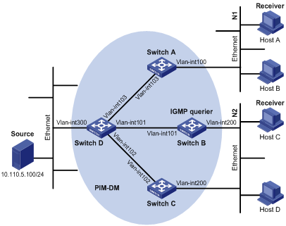
|
Device |
Interface |
IP address |
Device |
Interface |
IP address |
|
Switch A |
Vlan-int100 |
10.110.1.1/24 |
Switch D |
Vlan-int300 |
10.110.5.1/24 |
|
|
Vlan-int103 |
192.168.1.1/24 |
|
Vlan-int103 |
192.168.1.2/24 |
|
Switch B |
Vlan-int200 |
10.110.2.1/24 |
|
Vlan-int101 |
192.168.2.2/24 |
|
|
Vlan-int101 |
192.168.2.1/24 |
|
Vlan-int102 |
192.168.3.2/24 |
|
Switch C |
Vlan-int200 |
10.110.2.2/24 |
|
|
|
|
|
Vlan-int102 |
192.168.3.1/24 |
|
|
|
Networking and Configuration Requirements
l Receivers receive multicast VOD information through multicast. The receiver groups of different organizations form two stub networks, and at least one receiver host exists in each stub network. The entire PIM domain operates in the dense mode.
l Host A and Host C are multicast receivers in the two stub networks.
l Switch D connects to the network that comprises the multicast source (Source) through VLAN-interface 300.
l Switch A connects to stub network N1 through VLAN-interface 100, and to Switch D through VLAN-interface 103.
l Switch B and Switch C connect to stub network N2 through their respective VLAN-interface 200, and to Switch D through VLAN-interface 101 and VLAN-interface 102 respectively.
Application Product Matrix
|
Product series |
Software version |
Hardware version |
|
S3600-EI series |
Release 1510, Release 1602 |
All versions |
|
S5600 series |
Release 1510, Release 1602 |
All versions |
Configuration Procedure
Configuring the interface IP addresses and unicast routing protocol for each switch
Configure the IP address and subnet mask for each interface as perFigure 1-5. The detailed configuration steps are omitted here.
Configure OSPF for interoperation among the switches in the PIM-DM domain. Ensure the network-layer interoperation among Switch A, Switch B, Switch C, and Switch D in the PIM-DM domain and enable dynamic update of routing information among the switches via unicast.
Enabling IP multicast routing and enabling PIM-DM on each interface
# Enable IP multicast routing on Switch A, enable PIM-DM on each interface, and enable IGMP on VLAN-interface 100, which connects Switch A to the stub network.
<SwitchA> system-view
[SwitchA] multicast routing-enable
[SwitchA] interface vlan-interface 100
[SwitchA-Vlan-interface100] igmp enable
[SwitchA-Vlan-interface100] pim dm
[SwitchA-Vlan-interface100] quit
[SwitchA] interface vlan-interface 103
[SwitchA-Vlan-interface103] pim dm
[SwitchA-Vlan-interface103] quit
The configuration on Switch B and Switch C is similar to the configuration on Switch A.
# Enable multicast routing on Switch D, and enable PIM-DM on each interface.
<SwitchD> system-view
[SwitchD] multicast routing-enable
[SwitchD] interface vlan-interface 300
[SwitchD-Vlan-interface300] pim dm
[SwitchD-Vlan-interface300] quit
[SwitchD] interface vlan-interface 103
[SwitchD-Vlan-interface103] pim dm
[SwitchD-Vlan-interface103] quit
[SwitchD] interface vlan-interface 101
[SwitchD-Vlan-interface101] pim dm
[SwitchD-Vlan-interface101] quit
[SwitchD] interface vlan-interface 102
[SwitchD-Vlan-interface102] pim dm
[SwitchD-Vlan-interface102] quit
Verifying the configuration
Carry out the display pim neighbor command to view the PIM neighboring relationships among the switches. For example:
# View the PIM neighboring relationships on Switch D.
[SwitchD] display pim neighbor
Neighbor's Address Interface Name Uptime Expires
192.168.1.1 Vlan-interface1 00:47:08 00:01:39
192.168.2.1 Vlan-interface1 00:48:05 00:01:29
192.168.3.1 Vlan-interface1 00:49:08 00:01:34
Use the display pim routing-table command to view the PIM routing information on the switches. For example:
# View the PIM routing table on Switch A.
<SwitchA> display pim routing-table
PIM-DM Routing Table
Total 1 (S,G) entry
(10.110.5.100, 225.1.1.1)
Protocol 0x40: PIMDM, Flag 0xC: SPT NEG_CACHE
Uptime: 00:00:23, Timeout in 187 sec
Upstream interface: Vlan-interface103, RPF neighbor: 192.168.1.2
Downstream interface list:
Vlan-interface100, Protocol 0x1: IGMP, never timeout
Matched 1 (S,G) entry
The displayed information on Switch B and Switch C is similar to that on Switch A.
# View the PIM routing table on Switch D.
<SwitchD> display pim routing-table
PIM-DM Routing Table
Total 1 (S,G) entry
(10.110.5.100, 225.1.1.1)
Protocol 0x40: PIMDM, Flag 0xC: SPT NEG_CACHE
Uptime: 00:00:23, Timeout in 187 sec
Upstream interface: Vlan-interface300, RPF neighbor: NULL
Downstream interface list:
Vlan-interface101, Protocol 0x200: SPT, timeout in 147 sec
Vlan-interface103, Protocol 0x200: SPT, timeout in 145 sec
Vlan-interface103, Protocol 0x200: SPT, timeout in 145 sec
Matched 1 (S,G) entry
Complete Configuration
Configuration on Switch A
#
multicast routing-enable
#
interface Vlan-interface100
ip address 10.110.1.1 255.255.255.0.
igmp enable
pim dm
#
interface Vlan-interface103
ip address 192.168.1.1 255.255.255.0
pim dm
#
Configuration on Switch B
#
multicast routing-enable
#
interface Vlan-interface101
ip address 192.168.2.1 255.255.255.0.
pim dm
#
interface Vlan-interface200
ip address 10.110.2.1 255.255.255.0
igmp enable
pim dm
#
Configuration on Switch C
#
multicast routing-enable
#
interface Vlan-interface102
ip address 192.168.3.1 255.255.255.0.
pim dm
#
interface Vlan-interface200
ip address 10.110.2.2 255.255.255.0
igmp enable
pim dm
#
Configuration on Switch D
#
multicast routing-enable
#
interface Vlan-interface101
ip address 192.168.2.2 255.255.255.0.
pim dm
#
interface Vlan-interface102
ip address 192.168.3.2 255.255.255.0
pim dm
#
interface Vlan-interface103
ip address 192.168.1.2 255.255.255.0
pim dm
#
interface Vlan-interface300
ip address 10.110.5.1 255.255.255.0
pim dm
#
Precautions
Configuring Anycast RP Application
Network Diagram
Figure 1-6 Network diagram for anycast RP configuration
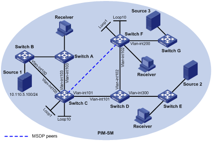
|
Device |
Interface |
IP address |
Device |
Interface |
IP address |
|
Switch A |
Vlan-int103 |
10.110.1.2/24 |
Switch D |
Vlan-int300 |
10.110.4.1/24 |
|
Switch B |
Vlan-int100 |
10.110.2.2/24 |
|
Vlan-int102 |
192.168.3.1 |
|
Switch C |
Vlan-int103 |
10.110.1.1/24 |
|
Vlan-int101 |
192.168.1.2/24 |
|
|
Vlan-int100 |
10.110.2.1/24 |
Switch F |
Vlan-int200 |
10.110.3.1/24 |
|
|
Vlan-int101 |
192.168.1.1/24 |
|
Vlan-int102 |
192.168.3.2/24 |
|
|
Loop1 |
3.3.3.3/32 |
|
Loop1 |
4.4.4.4/32 |
|
|
Loop10 |
10.1.1.1/32 |
|
Loop10 |
10.1.1.1/32 |
Networking and Configuration Requirements
l The PIM-SM domain in this example has multiple multicast sources and receivers. OSPF needs to run in the domain to provide unicast routes.
l The anycast RP application needs to be is configured in the PIM-SM domain, so that the last-hop switch joins the topologically nearest RP.
l An MSDP peering relationship needs to be set up between Switch C and Switch F.
l On Switch C and Switch F, the interface Loopback 1 needs to be configured as a C-BSR, and Loopback 10 as a C-RP.
l The router ID of Switch C is 1.1.1.1, while the router ID of Switch F is 2.2.2.2.
Application Product Matrix
|
Product series |
Software version |
Hardware version |
|
S3600-EI series |
Release 1510, Release 1602 |
All versions |
|
S5600 series |
Release 1510, Release 1602 |
All versions |
Configuration Procedure
Configuring the interface IP addresses and unicast routing protocol for each switch
Configure the IP address and subnet mask for each interface as perFigure 1-6. The detailed configuration steps are omitted here.
Configure OSPF for interconnection between the switches. The detailed configuration steps are omitted here.
Enabling IP multicast routing and enabling PIM-SM on each interface
# Enable multicast routing on Switch C, and enable PIM-SM on each interface.
<SwitchC> system-view
[SwitchC] multicast routing-enable
[SwitchC] interface vlan-interface 103
[SwitchC-Vlan-interface103] pim sm
[SwitchC-Vlan-interface103] quit
[SwitchC] interface vlan-interface 100
[SwitchC-Vlan-interface100] pim sm
[SwitchC-Vlan-interface100] quit
[SwitchC] interface Vlan-interface 101
[SwitchC-Vlan-interface101] pim sm
[SwitchC-Vlan-interface101] quit
The configuration on Switch A, Switch B, Switch D, Switch E, Switch F, and Switch G is similar to the configuration on Switch C. The specific configuration steps are omitted here.
Configuring the IP addresses of interface Loopback 1, Loopback 10, C-BSR, and C-RP
# Configure different Loopback 1 addresses and identical Loopback 10 address on Switch C and Switch F, configure a C-BSR on each Loopback 1 and configure a C-RP on each Loopback 10.
[SwitchC] interface loopback 1
[SwitchC-LoopBack1] ip address 3.3.3.3 255.255.255.255
[SwitchC-LoopBack1] pim sm
[SwitchC-LoopBack1] quit
[SwitchC] interface loopback 10
[SwitchC-LoopBack10] ip address 10.1.1.1 255.255.255.255
[SwitchC-LoopBack10] pim sm
[SwitchC-LoopBack10] quit
[SwitchC] pim
[SwitchC-pim] c-bsr loopback 1 24
[SwitchC-pim] c-rp loopback 10
[SwitchC-pim] quit
The configuration on Switch F is similar to the configuration on Switch C.
# View the PIM routing information on Switch C.
[SwitchC] display pim routing-table
PIM-SM Routing Table
Total 1 (S,G) entries, 0 (*,G) entry, 0 (*,*,RP) entry
(10.110.5.100, 225.1.1.1)
Protocol 0x20: PIMSM, Flag 0x80004: SPT
Uptime: 00:00:08, Timeout in 203 sec
Upstream interface: Vlan-interface1, RPF neighbor: NULL
Downstream interface list: NULL
Matched 1 (S,G) entries, 0 (*,G) entry, 0 (*,*,RP) entry
As shown above, the multicast source has been registered on Switch C, which is deemed as the RP.
# View the PIM routing information on Switch F.
<Switch F>dis pim routing-table
PIM-SM Routing Table
Total 0 (S,G) entry, 1 (*,G) entries, 0 (*,*,RP) entry
(*, 225.1.1.1), RP 10.1.1.1
Protocol 0x20: PIMSM, Flag 0x2003: RPT WC NULL_IIF
Uptime: 00:00:12, never timeout
Upstream interface: Null, RPF neighbor: 0.0.0.0
Downstream interface list:
Vlan-interface2, Protocol 0x1: IGMP, never timeout
Matched 0 (S,G) entry, 1 (*,G) entries, 0 (*,*,RP) entry
As shown above, the multicast receiver joins to Switch F, rooted at which an RPT has been established.
However, the RP for the multicast source is different from the RP for the multicast receiver, so the multicast receiver cannot receive multicast data yet. Anycast RP needs to be configured on these two RPs.
Configuring MSDP peers
# Configure an MSDP peer on Switch C.
[SwitchC] msdp
[SwitchC-msdp] originating-rp Vlan-interface 101
[SwitchC-msdp] peer 192.168.3.2 connect-interface Vlan-interface 101
[SwitchC-msdp] quit
# Configure an MSDP peer on Switch F.
[SwitchF] msdp
[SwitchF-msdp] originating-rp Vlan-interface 102
[SwitchF-msdp] peer 192.168.1.1 connect-interface Vlan-interface 102
[SwitchF-msdp] quit
You can use the display msdp brief command to view the brief information of MSDP peering relationships between the switches.
# View the brief MSDP peer information on Switch C.
[SwitchC] display msdp brief
MSDP Peer Brief Information
Peer's Address State Up/Down time AS SA Count Reset Count
192.168.3.2 Up 00:48:21 ? 2 0
# View the brief MSDP peer information on Switch F.
[SwitchF] display msdp brief
MSDP Peer Brief Information
Peer's Address State Up/Down time AS SA Count Reset Count
192.168.1.1 Up 00:50:22 ? 2 0
After the peering relationship is established, the multicast receiver can receive multicast data from the source.
# View the PIM routing information on Switch C again.
[Switch C] display pim routing-table
PIM-SM Routing Table
Total 1 (S,G) entries, 0 (*,G) entry, 0 (*,*,RP) entry
(10.110.5.100, 225.1.1.1)
Protocol 0x20: PIMSM, Flag 0x80004: SPT
Uptime: 00:00:55, Timeout in 208 sec
Upstream interface: Vlan-interface1, RPF neighbor: NULL
Downstream interface list:
Vlan-interface2, Protocol 0x200: SPT, timeout in 200 sec
Matched 1 (S,G) entries, 0 (*,G) entry, 0 (*,*,RP) entry
# View the PIM routing information on Switch F again.
[SwitchF] display pim routing-table
PIM-SM Routing Table
Total 1 (S,G) entry, 3 (*,G) entries, 0 (*,*,RP) entry
(*, 224.1.1.1), RP 10.1.1.1
Protocol 0x20: PIMSM, Flag 0x2003: RPT WC NULL_IIF
Uptime: 00:25:26, never timeout
Upstream interface: Null, RPF neighbor: 0.0.0.0
Downstream interface list:
Vlan-interface2, Protocol 0x1: IGMP, never timeout
(192.168.3.1, 224.1.1.1)
Protocol 0x20: PIMSM, Flag 0x4: SPT
Uptime: 00:02:56, Timeout in 202 sec
Upstream interface: Vlan-interface1, RPF neighbor: 192.168.1.1
Downstream interface list:
Vlan-interface2, Protocol 0x1: IGMP, never timeout
Matched 1 (S,G) entry, 3 (*,G) entries, 0 (*,*,RP) entry
Complete Configuration
Configuration on Switch C
#
multicast routing-enable
#
interface Vlan-interface100
ip address 10.110.1.1 255.255.255.0.
pim sm
#
interface Vlan-interface101
ip address 192.168.1.1 255.255.255.0
pim sm
#
interface Vlan-interface103
ip address 10.110.1.1 255.255.255.0
pim sm
#
interface LoopBack1
ip address 3.3.3.3 255.255.255.255
pim sm
#
interface LoopBack10
ip address 10.1.1.1 255.255.255.255
pim sm
#
pim
c-bsr LoopBack1 24
c-rp LoopBack10
#
msdp
originating-rp Vlan-interface101
peer 192.168.3.2 connect-interface Vlan-interface101
#
Configuration on Switch F
#
multicast routing-enable
#
interface Vlan-interface102
ip address 192.168.3.2 255.255.255.0
pim sm
#
interface Vlan-interface200
ip address 10.110.3.1 255.255.255.0
pim sm
#
interface LoopBack1
ip address 4.4.4.4 255.255.255.255
pim sm
#
interface LoopBack10
ip address 10.1.1.1 255.255.255.255
pim sm
#
pim
c-bsr LoopBack1 24
c-rp LoopBack10
#
msdp
originating-rp Vlan-interface102
peer 192.168.1.1 connect-interface Vlan-interface102
#
Precautions
Be sure to configure a 32-bit subnet mask (255.255.255.255) for the Anycast RP address, namely configure the Anycast RP address as a host address.