- Table of Contents
-
- H3C Low-End Ethernet Switches Configuration Guide(V1.01)
- 01-Login Configuration Guide
- 02-VLAN Configuration Guide
- 03-IP Address Configuration Guide
- 04-Voice VLAN Configuration Guide
- 05-GVRP Configuration Guide
- 06-Ethernet Interface Basic Configuration Guide
- 07-Link Aggregation Configuration Guide
- 08-Port Isolation Configuration Guide
- 09-Port Security Configuration Guide
- 10-Port Binding Configuration Guide
- 11-MAC Address Table Management Configuration Guide
- 12-DLDP Configuration Guide
- 13-Auto Detect Configuration Guide
- 14-MSTP Configuration Guide
- 15-Routing Configuration Guide
- 16-Multicast Configuration Guide
- 17-802.1x Configuration Guide
- 18-AAA Configuration Guide
- 19-MAC Authentication Configuration Guide
- 20-VRRP Configuration Guide
- 21-ARP Configuration Guide
- 22-DHCP Configuration Guide
- 23-ACL Configuration Guide
- 24-QoS-QoS Profile Configuration Guide
- 25-Web Cache Redirection Configuration Guide
- 26-Mirroring Configuration Guide
- 27-IRF Configuration Guide
- 28-Cluster Configuration Guide
- 29-PoE-PoE Profile Configuration Guide
- 30-UDP Helper Configuration Guide
- 31-SNMP-RMON Configuration Guide
- 32-NTP Configuration Guide
- 33-SSH Configuration Guide
- 34-FTP and TFTP Configuration Guide
- 35-Information Center Configuration Guide
- 36-VLAN-VPN Configuration Guide
- 37-HWPing Configuration Guide
- 38-DNS Configuration Guide
- 39-Access Management Configuration Guide
- 40-Web Authentication Configuration Guide
- 41-IPv6 Management Configuration Guide
- 42-Smart link - Monitor Link Configuration Guide
- 43-VLAN Mapping Configuration Guide
- Related Documents
-
| Title | Size | Download |
|---|---|---|
| 14-MSTP Configuration Guide | 167.81 KB |
Networking and Configuration Requirements
Configuring VLAN-VPN Tunneling
Networking and Configuration Requirements
Networking and Configuration Requirements
Configuring Digest Snooping and Rapid Transition
Networking and Configuration Requirements
1 MSTP Configuring Guide
Configuring MSTP
The Ethernet switches listed in Applicable Product Matrix support the Multiple Spanning Tree Protocol (MSTP), which allows you to map one or multiple VLANs to a multiple spanning tree instance (MSTI). Note that one VLAN can be mapped to only one MSTI. With MSTP, the packets of a specific VLAN are transmitted in the MSTI to which the VLAN is mapped, thus saving overhead and reducing resource utilization.
Network Diagram
Figure 1-1 Network diagram for MSTP configuration
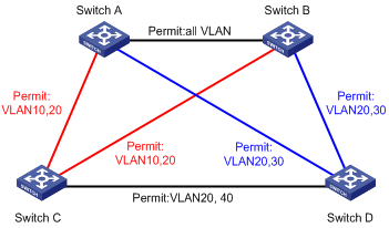
|
VLAN |
MSTI |
|
VLAN 10 |
MSTI 1 |
|
VLAN 20 |
MSTI 0 |
|
VLAN 30 |
MSTI 3 |
|
VLAN 40 |
MSTI 4 |
Networking and Configuration Requirements
Configure MSTP in the network shown in Figure 1-1 to enable packets of different VLANs to travel along different MSTIs. Do the following:
l Assign all switches in the network to the same MST region.
l Enable packets of VLAN 10, VLAN 30, VLAN 40, and VLAN 20 to travel along MSTI 1, MSTI 3, MSTI 4, and MSTI 0 respectively.
Applicable Product Matrix
|
Product series |
Software version |
Hardware version |
|
S5600 series |
Release 1510, Release1602 |
All versions |
|
S5100-SI/EI series |
Release 2200, Release2201 |
All versions |
|
S3600-SI/EI series |
Release 1510, Release1602 |
All versions |
|
S3100-EI series |
Release 2104, Release 2107 |
All versions |
|
S3100-C-SI series S3100-T-SI series |
Release 0011, Release 2102, Release 2107 |
All versions |
|
S3100-52P |
Release 1500, Release 1602 |
S3100-52P |
Configuration Procedure
1) Configuration on Switch A
# Enter MST region view.
<SwitchA> system-view
[SwitchA] stp region-configuration
# Configure the region name, VLAN-to-MSTI mapping, and revision level of the MST region.
[SwitchA-mst-region] region-name example
[SwitchA-mst-region] instance 1 vlan 10
[SwitchA-mst-region] instance 3 vlan 30
[SwitchA-mst-region] instance 4 vlan 40
[SwitchA-mst-region] revision-level 0
# Activate the MST region configuration manually.
[SwitchA-mst-region] active region-configuration
[SwitchA-mst-region] quit
# Specify Switch A as the root bridge of MSTI 1.
[SwitchA] stp instance 1 root primary
2) Configuration on Switch B
# Enter MST region view.
<SwitchB> system-view
[SwitchB] stp region-configuration
# Configure the region name, VLAN-to-MSTI mapping, and revision level of the MST region.
[SwitchB-mst-region] region-name example
[SwitchB-mst-region] instance 1 vlan 10
[SwitchB-mst-region] instance 3 vlan 30
[SwitchB-mst-region] instance 4 vlan 40
[SwitchB-mst-region] revision-level 0
# Activate the MST region configuration manually.
[SwitchB-mst-region] active region-configuration
[SwitchB-mst-region] quit
# Specify Switch B as the root bridge of MSTI 3.
[SwitchB] stp instance 3 root primary
3) Configuration on Switch C
# Configure the MST region.
<SwitchC> system-view
[SwitchC] stp region-configuration
[SwitchC-mst-region] region-name example
[SwitchC-mst-region] instance 1 vlan 10
[SwitchC-mst-region] instance 3 vlan 30
[SwitchC-mst-region] instance 4 vlan 40
[SwitchC-mst-region] revision-level 0
# Activate the MST region configuration manually.
[SwitchC-mst-region] active region-configuration
[SwitchC-mst-region] quit
# Specify Switch C as the root bridge of MSTI 4.
[SwitchC] stp instance 4 root primary
4) Configuration on Switch D
# Enter MST region view.
<SwitchD> system-view
[SwitchD] stp region-configuration
# Configure the MST region.
[SwitchD-mst-region] region-name example
[SwitchD-mst-region] instance 1 vlan 10
[SwitchD-mst-region] instance 3 vlan 30
[SwitchD-mst-region] instance 4 vlan 40
[SwitchD-mst-region] revision-level 0
# Activate the MST region configuration manually.
[SwitchD-mst-region] active region-configuration
Complete Configuration
l Configuration on Switch A
#
stp instance 1 root primary
stp region-configuration
region-name example
instance 1 vlan 10
instance 3 vlan 30
instance 4 vlan 40
active region-configuration
#
l Configuration on Switch B
#
stp instance 3 root primary
stp region-configuration
region-name example
instance 1 vlan 10
instance 3 vlan 30
instance 4 vlan 40
active region-configuration
#
l Configuration on Switch C
#
stp instance 4 root primary
stp region-configuration
region-name example
instance 1 vlan 10
instance 3 vlan 30
instance 4 vlan 40
active region-configuration
#
l Configuration on Switch D
#
stp region-configuration
instance 1 vlan 10
instance 3 vlan 30
instance 4 vlan 40
active region-configuration
#
Precautions
None
Configuring VLAN-VPN Tunneling
Network Diagram
Figure 1-2 Network diagram for VLAN-VPN tunneling configuration
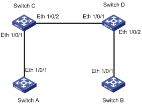
Networking and Configuration Requirements
l Use Switch C and Switch D (which can be S3600 series switches or S5600 series switches) as access devices of the service provider network.
l Use Switch A and Switch B (which can be S3100 series switches or S5100 series switches) as access devices of the customer networks.
Applicable Product Matrix
|
Product series |
Software version |
Hardware version |
|
S5600 series |
Release 1510, Release1602 |
All versions |
|
S5100-SI/EI series |
Release 2200, Release2201 |
All versions |
|
S3600-SI/EI series |
Release 1510, Release1602 |
All versions |
|
S3100-C-SI series S3100-T-SI series |
Release 0011, Release 2102, Release 2107 |
All versions |
|
S3100-52P |
Release 1500, Release 1602 |
S3100-52P |
Configuration Procedure
1) Configuration on Switch A
# Enable MSTP.
<SwitchA> system-view
[SwitchA] stp enable
# Add Ethernet 1/0/1 to VLAN 10.
[SwitchA] vlan 10
[SwitchA-vlan10] port Ethernet1/0/1
2) Configuration on Switch B
# Enable MSTP.
<SwitchB> system-view
[SwitchB] stp enable
# Add Ethernet 1/0/1 to VLAN 10.
[SwitchB] vlan 10
[SwitchB-vlan10] port Ethernet1/0/1
3) Configuration on Switch C
# Enable MSTP.
<SwitchC> system-view
[SwitchC] stp enable
# Enable VLAN-VPN tunneling.
[SwitchC] vlan-vpn tunnel
# Add Ethernet 1/0/1 to VLAN 10.
[SwitchC] vlan 10
[SwitchC-vlan10] port Ethernet1/0/1
[SwitchC-vlan10] quit
# Enable VLAN VPN.
[SwitchC] interface Ethernet1/0/1
[SwitchC-Ethernet1/0/1] vlan-vpn enable
[SwitchC-Ethernet1/0/1] quit
# Configure Ethernet 1/0/2 as a trunk port, and assign the port to VLAN 10.
[SwitchC] interface Ethernet1/0/2
[SwitchC-Ethernet1/0/2] port link-type trunk
[SwitchC-Ethernet1/0/2] port trunk permit vlan 10
4) Configuration on Switch D
# Enable MSTP.
<SwitchD> system-view
[SwitchD] stp enable
# Enable VLAN-VPN tunneling.
[SwitchD] vlan-vpn tunnel
# Add Ethernet 1/0/2 to VLAN 10.
[SwitchD] vlan 10
[SwitchD-vlan10] port Ethernet1/0/2
[SwitchD-vlan10] quit
# Enable VLAN VPN.
[SwitchD] interface Ethernet1/0/2
[SwitchD-Ethernet1/0/2] vlan-vpn enable
[SwitchD-Ethernet1/0/2] quit
# Configure Ethernet 1/0/1 as a trunk port, and assign the port to VLAN 10.
[SwitchD] interface Ethernet1/0/1
[SwitchD-Ethernet1/0/1] port link-type trunk
[SwitchD-Ethernet1/0/1] port trunk permit vlan 10
Complete Configuration
1) Configuration on Switch A
#
stp enable
#
interface Ethernet1/0/1
port access vlan 10
#
2) Configuration on Switch B
#
stp enable
#
interface Ethernet1/0/1
port access vlan 10
#
3) Configuration on Switch C
#
stp enable
#
vlan-vpn tunnel
#
interface Ethernet1/0/1
stp disable
port access vlan 10
vlan-vpn enable
#
interface Ethernet1/0/2
port link-type trunk
port trunk permit vlan 1 10
#
4) Configuration on Switch D
#
stp enable
#
vlan-vpn tunnel
#
interface Ethernet1/0/2
stp disable
port access vlan 10
vlan-vpn enable
#
interface Ethernet1/0/1
port link-type trunk
port trunk permit vlan 1 10
#
Precautions
The bpdu-tunnel stp command is mutually exclusive with the vlan-vpn tunnel command.
Configuring RSTP
The switches listed inApplicable Product Matrix work in MSTP mode by default. To implement RSTP, configure the stp mode command on them to have them work in RSTP mode.
Network Diagram
Figure 1-3 Network diagram for RSTP configuration
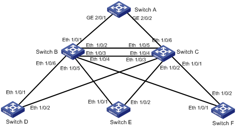
Networking and Configuration Requirements
l Switch A is operating at the core.
l Switch B and Switch C are operating at the distribution layer.
l Switch D, Switch E, and Switch F are operating at the access layer.
At the distribution layer:
l Switch C is operating as the backup switch of Switch B. When Switch B fails, Switch C takes over.
l Switch C and Switch B are connected through two links. When a link fails, another link takes over.
At the access layer:
l Switch D, Switch E, and Switch F are directly connected to PCs.
l Switch D, Switch E, and Switch F are connected to Switch C and Switch B.
In the configuration procedure below, only RSTP-related configurations are provided. Switch A is the root bridge. Switch D through Switch F are mostly consistent in the configuration, so only the configuration on Switch D is listed.
![]()
l In most cases, Switch A is a high-end switch or middle-range switch, such as a S9500 switch or S7500 switch.
l In most cases, Switch B and Switch C are low-end switches such as S3600 series switches and S5600 series switches.
l In most cases, Switch D, Switch E, and Switch F are S3100 series switches and S5100 series switches of the low-end switches.
Applicable Product Matrix
|
Product series |
Software version |
Hardware version |
|
S5600 series |
Release 1510, Release1602 |
All versions |
|
S5100-SI/EI series |
Release 2200, Release2201 |
All versions |
|
S3600-SI/EI series |
Release 1510, Release1602 |
All versions |
|
S3100-EI series |
Release 2104, Release 2107 |
All versions |
|
S3100-C-SI series S3100-T-SI series |
Release 0011, Release 2102, Release 2107 |
All versions |
|
S3100-52P |
Release 1500, Release 1602 |
S3100-52P |
Configuration Procedure
1) Configuration on Switch A
# Configure Switch A to work in RSTP-compatible mode.
<SwitchA> system-view
[SwitchA] stp mode rstp
# Configure Switch A as the root bridge in one of the following two methods:
l Set the bridge priority of Switch A to 0.
[SwitchA] stp priority 0
l Use the following command to specify Switch A as the root bridge.
[SwitchA] stp root primary
# Enable the root guard function on the designated ports connected to Switch B and Switch C.
[SwitchA] interface GigabitEthernet 2/0/1
[SwitchA -GigabitEthernet2/0/1] stp root-protection
[SwitchA -GigabitEthernet2/0/1] quit
[SwitchA] interface GigabitEthernet 2/0/2
[SwitchA -GigabitEthernet2/0/2] stp root-protection
[SwitchA -GigabitEthernet2/0/2] quit
# Enable the TC-BPDU attack guard function on Switch A.
[SwitchA] stp tc-protection enable
# Enable RSTP on Switch A.
[SwitchA] stp enable
# Disable RSTP on all ports that do not participate in RSTP calculation, GigabitEthernet 2/0/4 for example. (You need to do this because enabling RSTP on a switch enables RSTP on all ports by default.)
[SwitchA] interface GigabitEthernet 2/0/4
[SwitchA-GigabitEthernet2/0/4] stp disable
2) Configuration on Switch B
# Configure Switch B to work in RSTP-compatible mode.
<SwitchB> system-view
[SwitchB] stp mode rstp
# Configure Switch C and Switch B to back up each other, and set the bridge priority of Switch B to 4096.
[SwitchB] stp priority 4096
# Enable the root guard function on each designated port.
[SwitchB] interface Ethernet 1/0/4
[SwitchB-Ethernet1/0/4] stp root-protection
[SwitchB-Ethernet1/0/4] quit
[SwitchB] interface Ethernet 1/0/5
[SwitchB-Ethernet1/0/5] stp root-protection
[SwitchB-Ethernet1/0/5] quit
[SwitchB] interface Ethernet 1/0/6
[SwitchB-Ethernet1/0/6] stp root-protection
[SwitchB-Ethernet1/0/6] quit
# Enable RSTP on Switch B.
[SwitchB] stp enable
# Disable RSTP on all ports that do not participate in RSTP calculation, Ethernet 1/0/8 for example.
[SwitchB] interface Ethernet 1/0/8
[SwitchB-Ethernet1/0/8] stp disable
# Adopt the default RSTP time-related parameters and port parameters.
3) Configuration on Switch C
# Configure Switch C to work in RSTP-compatible mode.
<SwitchC> system-view
[SwitchC] stp mode rstp
# Configure Switch C and Switch B to back up each other, and set the bridge priority of Switch C to 8192.
[SwitchC] stp priority 8192
# Enable the root guard function on each designated port.
[SwitchC] interface Ethernet 1/0/1
[SwitchC-Ethernet1/0/1] stp root-protection
[SwitchC-Ethernet1/0/1] quit
[SwitchC] interface Ethernet 1/0/2
[SwitchC-Ethernet1/0/2] stp root-protection
[SwitchC-Ethernet1/0/2] quit
[SwitchC] interface Ethernet 1/0/3
[SwitchC-Ethernet1/0/3] stp root-protection
[SwitchC-Ethernet1/0/3] quit
# Enable RSTP on Switch C.
[SwitchC] stp enable
# Disable RSTP on all ports that do not participate in RSTP calculation, Ethernet 1/0/8 for example.
[SwitchC] interface Ethernet 1/0/8
[SwitchC-Ethernet1/0/8] stp disable
# Adopt the default RSTP time-related parameters and port parameters.
4) Configuration on Switch D
# Configure Switch D to work in RSTP-compatible mode.
<SwitchD> system-view
[SwitchD] stp mode rstp
# Configure the ports directly connected to users as edge ports and enable the BPDU guard function on these ports. Take Ethernet 1/0/3 for example.
[SwitchD-Ethernet1/0/3] stp edged-port enable
[SwitchD-Ethernet1/0/3] quit
[SwitchD] stp bpdu-protection
# Enable RSTP on Switch D.
[SwitchD] stp enable
# Disable RSTP on all ports that do not participate in RSTP calculation, Ethernet 1/0/3 for example.
[SwitchD] interface Ethernet 1/0/3
[SwitchD-Ethernet1/0/3] stp disable
# Adopt the default RSTP time-related parameters and port parameters.
# The configuration on Switch E and Switch F are the same as that on Switch D.
Complete Configuration
1) Configuration on Switch A
#
stp mode rstp
stp instance 0 priority 0
(stp instance 0 root primary)
stp TC-protection enable
stp enable
#
interface GigabitEthernet2/0/1
stp root-protection
#
interface GigabitEthernet2/0/2
stp root-protection
#
interface GigabitEthernet2/0/4
stp disable
#
2) Configuration on Switch B
#
stp mode rstp
stp instance 0 priority 4096
stp enable
#
interface Ethernet1/0/4
stp root-protection
#
interface Ethernet1/0/5
stp root-protection
#
interface Ethernet1/0/6
stp root-protection
#
interface Ethernet1/0/8
stp disable
#
3) Configuration on Switch C
#
stp mode rstp
stp instance 0 priority 8192
stp enable
#
interface Ethernet1/0/1
stp root-protection
#
interface Ethernet1/0/2
stp root-protection
#
interface Ethernet1/0/3
stp root-protection
#
interface Ethernet1/0/8
stp disable
#
4) Configuration on Switch D
#
stp mode rstp
stp enable
#
interface Ethernet1/0/3
stp disable
interface Ethernet3/0/5
stp edged-port enable
stp bpdu-protection
#
Precautions
None
Configuring Digest Snooping and Rapid Transition
Digest Snooping
The H3C switches listed in Applicable Product Matrix support MSTP. On a network comprising devices of multiple vendors, H3C switches cannot interoperate with switches that run proprietary spanning tree protocols in the same MSTP region, even if they are configured with the same MST region-related settings.
To address the problem, you can enable digest snooping on the ports connected to switches running proprietary spanning tree protocols.
Rapid Transition
The proprietary spanning tree protocols of some vendors provide port state transition mechanisms similar to RSTP. For a switch running such a proprietary protocol, its rapid port state transition mechanism may fail on the designation port when the switch is downlinked to an MSTP-enabled H3C switch.
To address the problem, you can enable the rapid transition feature on the downstream H3C switch.
Network Diagram
Figure 1-4 Network diagram for digest snooping and rapid transition configuration
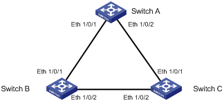
Networking and Configuration Requirements
l Use another vendor’s switch, Switch A in this scenario, as the root switch.
l Switch B and Switch C are connected to Switch A.
For Switch B:
l Set the priority of Switch B to 4096.
l Enable rapid transition and digest snooping on Switch B.
For Switch C:
l Set the priority of Switch C to 8192.
l Enable rapid transition and digest snooping on Switch C.
Applicable Product Matrix
|
Product series |
Software version |
Hardware version |
|
S5600 series |
Release 1510, Release1602 |
All versions |
|
S5100-SI/EI series |
Release 2200, Release2201 |
All versions |
|
S3600-SI/EI series |
Release 1510, Release1602 |
All versions |
|
S3100-EI series |
Release 2104, Release 2107 |
All versions |
|
S3100-C-SI series S3100-T-SI series |
Release 0011, Release 2102, Release 2107 |
All versions |
|
S3100-52P |
Release 1500, Release 1602 |
S3100-52P |
Configuration Procedure
1) Configuration on Switch B
# Enable MSTP.
<SwitchB> system-view
[SwitchB] stp enable
# Set the priority of Switch B to 4096.
[SwitchB] stp priority 4096
# Enable digest snooping on Switch B.
[SwitchB] stp config-digest-snooping
# Enable digest snooping on the root port Ethernet 1/0/1.
[SwitchB] interface Ethernet 1/0/1
[SwitchB-Ethernet1/0/1] stp config-digest-snooping
# Enable rapid transition on the root port Ethernet 1/0/1.
[SwitchB-Ethernet1/0/1] stp no-agreement-check
[SwitchB-Ethernet1/0/1] quit
2) Configuration on Switch C
# Enable MSTP.
<SwitchC> system-view
[SwitchC] stp enable
# Set the priority of Switch C to 8192.
[SwitchC] stp priority 8192
# Enable digest snooping on Switch C.
[SwitchC] stp config-digest-snooping
# Enable digest snooping on the root port Ethernet 1/0/2.
[SwitchC] interface Ethernet 1/0/2
[SwitchC-Ethernet1/0/2] stp config-digest-snooping
[SwitchC-Ethernet1/0/2] quit
# Enable rapid transition on Ethernet 1/0/1.
[SwitchC] interface Ethernet 1/0/1
[SwitchC-Ethernet1/0/1] stp no-agreement-check
[SwitchC-Ethernet1/0/1] quit
Complete Configuration
1) Configuration on Switch B
#
stp enable
stp instance 0 priority 4096
stp config-digest-snooping
#
interface Ethernet1/0/1
stp config-digest-snooping
stp no-agreement-check
#
2) Configuration on Switch C
#
stp enable
stp instance 0 priority 8192
stp config-digest-snooping
#
interface Ethernet1/0/1
stp no-agreement-check
#
interface Ethernet1/0/2
stp config-digest-snooping
Precautions
l The digest snooping feature is needed only when your switch is connected to another manufacturer’s switches adopting proprietary spanning tree protocols.
l To enable the digest snooping feature successfully, you must first enable it on all the ports of your switch that are connected to another manufacturer’s switches adopting proprietary spanning tree protocols and then enable it globally.
l To enable the digest snooping feature, the interconnected switches and another manufacturer’s switch adopting proprietary spanning tree protocols must be configured with exactly the same MST region-related configurations (including region name, revision level, and VLAN-to-MSTI mapping).
l The digest snooping feature must be enabled on all the switch ports that connect to another manufacturer’s switches adopting proprietary spanning tree protocols in the same MST region.
l The digest snooping feature is not applicable to boundary ports in an MST region.
l The digest snooping feature is not applicable to edge ports in an MST region.
l The rapid transition feature can be enabled only on root ports or alternate ports.
l You can enable rapid transition on a designated port, but the configuration cannot take effect on the port.