- Table of Contents
-
- H3C S3610[S5510] Series Ethernet Switches Operation Manual-Release 5301-(V1.03)
- 00-1Cover
- 00-2Product Overview
- 01-Login Configuration
- 02-VLAN Configuration
- 03-IP Addressing and Performance Configuration
- 04-QinQ-BPDU Tunneling Configuration
- 05-Port Correlation Configuration
- 06-Link Aggregation Configuration
- 07-MAC Address Table Management Configuration
- 08-IP Source Guard Configuration
- 09-MSTP Configuration
- 10-IPv6 Configuration
- 11-Routing Overview
- 12-IPv4 Routing Configuration
- 13-BFD-GR Configuration
- 14-IPv6 Routing Configuration
- 15-Multicast Protocol Configuration
- 16-802.1x-HABP-MAC Authentication Configuration
- 17-AAA-RADIUS-HWTACACS Configuration
- 18-ARP Configuration
- 19-DHCP Configuration
- 20-ACL Configuration
- 21-QoS Configuration
- 22-Port Mirroring Configuration
- 23-Cluster Management Configuration
- 24-UDP Helper Configuration
- 25-SNMP-RMON Configuration
- 26-NTP Configuration
- 27-DNS Configuration
- 28-File System Management Configuration
- 29-Information Center Configuration
- 30-System Maintaining and Debugging Configuration
- 31-NQA Configuration
- 32-VRRP Configuration
- 33-SSH Configuration
- 34-MCE Configuration
- 35-OAM Configuration
- 36-DLDP Configuration
- 37-RRPP Configuration
- 38-SSL-HTTPS Configuration
- 39-PKI Configuration
- 40-Appendix
- Related Documents
-
| Title | Size | Download |
|---|---|---|
| 21-QoS Configuration | 362 KB |
Table of Contents
1.2 Traditional Packet Forwarding Service
1.3 New Requirements Brought forth by New Services
1.4 Occurrence and Influence of Congestion and the Countermeasures
1.4.1 Occurrence of Congestion
1.5 Major Traffic Management Techniques
Chapter 2 Traffic Classification, TP, and TS Configuration
2.1 Traffic Classification Overview
2.3 Traffic Evaluation and the Token Bucket
2.3.2 Evaluating the traffic with the token bucket
Chapter 3 QoS Policy Configuration
3.3 Introduction to QoS Policies
3.4.1 Configuration Prerequisites
3.4.3 Defining a Traffic Behavior
Chapter 4 Congestion Management
4.2 Congestion Management Policy
4.6 Displaying Congestion Management
5.2 Configuring a Priority Mapping Table
5.2.1 Configuration Prerequisites
5.3 Configuring the Port Priority
5.3.1 Configuration Prerequisites
5.4 Configuring Port Priority Trust Mode
5.4.1 Configuration Prerequisites
5.5 Displaying Priority Mapping
Chapter 6 Congestion Avoidance
6.2.1 Configuration Prerequisites
6.3.1 Configuration Prerequisites
6.4 Displaying and Maintaining Congestion Avoidance
Chapter 7 Aggregation CAR Configuration
7.2 Applying Aggregation CAR on Ports
7.2.1 Configuration Prerequisites
7.3.1 Applying Aggregation CAR to a Port or a Port Group
7.3.2 Referencing Aggregation CAR in a Traffic Behavior
7.4 Displaying and Maintaining Aggregation CAR
Chapter 8 VLAN Policy Configuration
8.2.1 Configuration Prerequisites
8.3 Displaying and Maintaining VLAN Policy
8.4 VLAN Policy Configuration Examples
Chapter 9 Traffic Mirroring Configuration
9.2 Configuring Traffic Mirroring
9.3 Displaying Traffic Mirroring
9.4 Traffic Mirroring Configuration Examples
Chapter 1 QoS Overview
1.1 Introduction
In Internet, QoS measures the ability of the network to deliver packets. The evaluation on QoS can be based on different aspects because the network provides diversified services. Generally speaking, QoS is the evaluation on the service ability to support the critical indexes such as delay, delay jitter and packet loss rate in packet delivery.
1.2 Traditional Packet Forwarding Service
In traditional IP networks, packets are treated equally. That is, the FIFO (first in first out) policy is adopted for packet processing. Network resources required for packet forwarding is determined by the order in which packets arrive. All the packets share the resources of the network. Network resources available to the packets completely depend on the time they arrive. This service policy is known as Best-effort, which delivers the packets to their destination with the best effort, with no assurance and guarantee for delivery delay, jitter, packet loss ratio, reliability, and so on.
The traditional Best-Effort service policy is only suitable for applications insensitive to bandwidth and delay, such as WWW, file transfer and E-mail.
1.3 New Requirements Brought forth by New Services
With the fast development of computer networks, more and more networks are connected into Internet. Internet extends very quickly in scale, coverage and the number of users. More and more users use the Internet as a platform for data transmission and develop various applications on it.
Besides traditional applications such as WWW, FTP, and E-mail, Internet users also try to develop new services on Internet, such as tele-education, tele-medicine, video phones, video conferencing, and video on demand (VOD). Enterprise users also hope to connect their branch offices in different locations through the VPN technology to develop some transaction applications, such as to access to the database of the company or to manage remote switches through Telnet.
The new services have one thing in common: they all have special requirements for delivery performances such as bandwidth, delay, and delay jitter. For example, video conferencing and VOD require the guarantee of high bandwidth, low delay and low delay jitter. Some key services such as the transaction handling and the Telnet do not necessarily require high bandwidth but they are highly dependent on low delay and need to be processed preferentially in case of congestion.
The emergence of new services brings forward higher requirements for the service capability of the IP network. In the delivery process, users hope to get better services, such as dedicated bandwidth for users, reduced packet loss rate, management and avoidance of network congestion, control of network traffic, provision of packet priority, and so on, instead of just having packets delivered to the destination. To meet these requirements, the network service capability need to be further improved.
1.4 Occurrence and Influence of Congestion and the Countermeasures
QoS issues that traditional networks face are mainly caused by congestion. Congestion means reduced service rate and extra delay introduced because of relatively insufficient resource provisioned.
1.4.1 Occurrence of Congestion
Congestion is very common in a complicated environment of packet switching on Internet. The diagram below gives two examples:
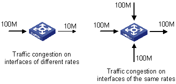
1) Packets enter a switch over a high-speed link and are forwarded out over a low-speed link.
2) Packets enter a switch through multiple interfaces of the same rate at the same time and are forwarded out on an interface of the same rate.
If the outbound traffic exceeds the line rate, the traffic encounters the bottleneck of resources and congestion occurs.
Besides bandwidth bottleneck, any insufficiency of resources for packet forwarding, such as insufficiency of assignable processor time, buffer size, and memory resources can cause congestion. In addition, congestion will also occur if the traffic that arrives within a certain period of time is improperly controlled and the traffic goes beyond the assignable network resources.
1.4.2 Influence of Congestion
Congestion may cause a series of negative influences:
l Congestion increases delay and delay jitter in packet delivery.
l Excessively high delay will cause retransmission of packets.
l Congestion decreases the effective throughput of the network and the utilization of the network resources.
l Aggravated congestion will consume a large amount of network resources (especially memory resources), and unreasonable resource assignment will even lead to system resource deadlock and cause the system breakdown.
It is obvious that congestion is the root of service performance declination because congestion makes traffic unable to get resources timely. However, congestion is common in a complicated environment where packet switching and multi-user services coexist. Therefore, congestion must be treated carefully.
1.4.3 Countermeasures
Increasing network bandwidth is a direct way to solve the problem of resource insufficiency, but it cannot solve all the problems that cause network congestion.
A more effective way to solve network congestion problems is to enhance the function of the network layer in traffic control and resource assignment, to provide differentiated services for different requirements, and to assign and utilize resources correctly. In the process of resource assignment and traffic control, the direct or indirect factors that may cause network congestion must be properly controlled so as to reduce the probability of congestion. When congestion occurs, the resource assignment should be balanced according to the features and requirements of all the services to minimize the influence of congestion on QoS.
1.5 Major Traffic Management Techniques
Traffic classification, traffic policing (TP), traffic shaping (TS), congestion management, and congestion avoidance are the foundation for providing differentiated services. Their main functions are as follows:
l Traffic classification: Identifies packets according to certain match rules. Traffic classification is the prerequisite of providing differentiated services.
l TP: Monitors and controls the specifications of specific traffic entering the device. When the traffic exceeds the threshold, restrictive or punitive measures can be taken to protect the business interests and network resources of the operator from being damaged.
l Congestion management: Congestion management is necessary for solving resource competition. Congestion management is generally to cache packets in the queues and arrange the forwarding sequence of the packets based on a certain scheduling algorithm.
l Congestion avoidance: Excessive congestion will impair the network resources. Congestion avoidance is to supervise the network resource usage. When it is found that congestion is likely to become worse, the congestion avoidance mechanism will drop packets and regulate traffic to solve the overload of the network.
l TS: TS is a traffic control measure to regulate the output rate of the traffic actively. TS regulates the traffic to match the network resources that can be provided by the downstream devices so as to avoid unnecessary packet loss and congestion.
Among the traffic management techniques, traffic classification is the basis because it identifies packets according to certain match rules, which is the prerequisite of providing differentiated services. TP, TS, congestion management, and congestion avoidance control network traffic and assigned resources from different approaches, and are the concrete ways of providing differentiated services.
Chapter 2 Traffic Classification, TP, and TS Configuration
When configuring traffic classification, TP, and TS, go to these section for information you are interested in:
l Traffic Classification Overview
l Traffic Evaluation and the Token Bucket
2.1 Traffic Classification Overview
2.1.1 Traffic Classification
A traffic classification rule can use the precedence bits in the type of service (ToS) field of the IP packet header to identify traffic with different precedence characteristics. A traffic classification rule can also classify traffic according to the traffic classification policy set by the network administrator, such as the combination of source addresses, destination addresses, MAC addresses, IP protocol or the port numbers of the applications. Traffic classification is generally based on the information in the packet header and rarely based on the content of the packet. The classification result is unlimited in range. They can be a small range specified by a quintuplet (source address, source port number, protocol number, destination address, and destination port number), or all the packets to a certain network segment.
Generally, the precedence of bits in the ToS field of the packet header is set when packets are classified on the network border. Thus, IP precedence can be used directly as the classification criterion inside the network. Queue techniques can also process packets differently according to IP precedence. The downstream network can either accept the classification results of the upstream network or re-classify the packets according to its own criterion.
The purpose of traffic classification is to provide differentiated services, so traffic classification is significant only when it is associated with a certain traffic control or resource assignment action. The specific traffic control action to be adopted depends on the phase and the current load status. For example, when the packets enter the network, TP is performed on the packets according to CIR; before the packets flow out of the node, TS is performed on the packets; when congestion occurs, queue scheduling is performed on the packets; when congestion get worse, congestion avoidance is performed on the packets.
2.1.2 Priority
The following describes several types of precedence:
1) IP precedence, ToS precedence, and DSCP precedence
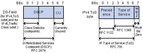
Figure 2-1 DS field and ToS field
The ToS field in an IP header contains eight bits, which are described as follows:
l The first three bits indicate IP precedence in the range of 0 to 7.
l Bit 3 to bit 6 indicate ToS precedence in the range of 0 to 15.
l RFC2474 re-defines the ToS field in the IP packet header, which is called the DS field. The first six (bit 0 to bit 5) bits of the DS field indicate DSCP precedence in the range of 0 to 63. The last two bits (bit 6 and bit 7) are reserved bits.
Table 2-1 Description on IP Precedence
|
IP Precedence (decimal) |
IP Precedence (binary) |
Description |
|
0 |
000 |
Routine |
|
1 |
001 |
priority |
|
2 |
010 |
immediate |
|
3 |
011 |
flash |
|
4 |
100 |
flash-override |
|
5 |
101 |
critical |
|
6 |
110 |
internet |
|
7 |
111 |
network |
In a network providing differentiated services, traffics are grouped into the following four classes, and packets are processed according to their DSCP values.
l Expedited Forwarding (EF) class: In this class, packets can be forwarded regardless of link share of other traffic. The class is suitable for preferential services with low delay, low packet loss ratio, low jitter, and assured bandwidth (such as virtual leased line);
l Assured forwarding (AF) class: This class is further divided into four subclasses (AF1/2/3/4) and a subclass is further divided into three drop priorities, so the AF service level can be segmented. The QoS rank of the AF class is lower than that of the EF class;
l Class selector (CS) class: This class comes from the IP ToS field and includes eight subclasses;
Table 2-2 Description on DSCP precedence values
|
DSCP value (decimal) |
DSCP value (binary) |
Description |
|
46 |
101110 |
ef |
|
10 |
001010 |
af11 |
|
12 |
001100 |
af12 |
|
14 |
001110 |
af13 |
|
18 |
010010 |
af21 |
|
20 |
010100 |
af22 |
|
22 |
010110 |
af23 |
|
26 |
011010 |
af31 |
|
28 |
011100 |
af32 |
|
30 |
011110 |
af33 |
|
34 |
100010 |
af41 |
|
36 |
100100 |
af42 |
|
38 |
100110 |
af43 |
|
8 |
001000 |
cs1 |
|
16 |
010000 |
cs2 |
|
24 |
011000 |
cs3 |
|
32 |
100000 |
cs4 |
|
40 |
101000 |
cs5 |
|
48 |
110000 |
cs6 |
|
56 |
111000 |
cs7 |
|
0 |
000000 |
be (default) |
802.1p priority lies in Layer 2 packet headers and is applicable to occasions where the Layer 3 packet header does not need analysis but QoS must be assured at Layer 2.
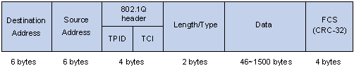
Figure 2-2 An Ethernet frame with an 802.1Q tag header
As shown in the figure above, the 4-byte 802.1Q tag header contains a 2-byte Tag Protocol Identifier (TPID) whose value is 8100 and a 2-byte Tag Control Information (TCI). TPID is a new class defined by IEEE to indicate a packet with an 802.1Q tag. Figure 2-3 describes the detailed contents of an 802.1Q tag header.
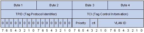
In the figure above, the 3-bit priority field in TCI is 802.1p priority in the range of 0 to 7. In the figure above, the priority field (three bits in length) in TCI is 802.1p priority (also known as CoS precedence), which ranges from 0 to 7.
Table 2-3 Description on 802.1p priority
|
802.1p priority (decimal) |
802.1p priority (binary) |
Description |
|
0 |
000 |
best-effort |
|
1 |
001 |
background |
|
2 |
010 |
spare |
|
3 |
011 |
excellent-effort |
|
4 |
100 |
controlled-load |
|
5 |
101 |
video |
|
6 |
110 |
voice |
|
7 |
111 |
network-management |
The precedence is called 802.1p priority because the related applications of this precedence are defined in detail in the 802.1p specifications.
2.2 TP and TS Overview
If the traffic from users is not limited, a large amount of continuous burst packets will result in worse network congestion. The traffic of users must be limited in order to make better use of the limited network resources and provide better service for more users. For example, if a traffic flow obtains only the resources committed to it within a certain period of time, network congestion due to excessive burst traffic can be avoided.
TP and TS are traffic control policies for limiting traffic and resource usage by supervising the traffic. The prerequisite for TP or TS is to determine whether or not the traffic exceeds the set threshold. Traffic control policies are adopted only when the traffic exceeds the set threshold. Generally, token bucket is used for evaluating traffic.
2.3 Traffic Evaluation and the Token Bucket
2.3.1 Token bucket
The token bucket can be considered as a container with a certain capacity to hold tokens. The system puts tokens into the bucket at the set rate. When the token bucket is full, the extra tokens will overflow and the number of tokens in the bucket stops increasing.
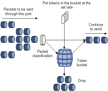
Figure 2-4 Evaluate the traffic with the token bucket
2.3.2 Evaluating the traffic with the token bucket
The evaluation for the traffic specification is based on whether the number of tokens in the bucket can meet the need of packet forwarding. If the number of tokens in the bucket is enough to forward the packets, the traffic is conforming to the specification; otherwise, the traffic is nonconforming or excess.
When the token bucket evaluates the traffic, its parameter configurations include:
l Average rate: The rate at which tokens are put into the bucket, namely, the permitted average rate of the traffic. It is generally set to committed information rate (CIR).
l Burst size: The capacity of the token bucket, namely, the maximum traffic size that is permitted in each burst. It is generally set to committed burst size (CBS). The set burst size must be greater than the maximum packet length.
An evaluation is performed on the arrival of each packet. In each evaluation, if the bucket has enough tokens for use, the traffic is controlled within the specification and a number of tokens equivalent to the packet forwarding authority must be taken out; otherwise, this means too many tokens have been used — the traffic is in excess of the specification.
2.3.3 Complicated evaluation
You can set two token buckets in order to evaluate more complicated conditions and implement more flexible regulation policies. For example, TP uses four parameters:
l CIR
l CBS
l Peak information rate (PIR)
l Excess burst size (EBS)
Two token buckets are used in this evaluation. Their rates of putting tokens into the buckets are CIR and PIR respectively, and their sizes are CBS and EBS respectively (the two buckets are called C bucket and E bucket respectively for short), representing different permitted burst levels. In each evaluation, you can implement different regulation policies in different conditions, including “enough tokens in C bucket”, “insufficient tokens in C bucket but enough tokens in E bucket” and “insufficient tokens in both C bucket and E bucket”.
2.3.4 TP
The typical application of TP is to supervise the specification of certain traffic into the network and limit it within a reasonable range, or to "discipline" the extra traffic. In this way, the network resources and the interests of the operators are protected. For example, you can limit HTTP packets to be within 50% of the network bandwidth. If the traffic of a certain connection is excess, TP can choose to drop the packets or to reset the priority of the packets.
TP is widely used in policing the traffic into the network of internet service providers (ISPs). TP can classify the policed traffic and perform pre-defined policing actions based on different evaluation results. These actions include:
l Forwarding conforming packets or non-conforming packets.
l Dropping conforming or non-conforming packets.
l Marking a conforming packet with a new 802.1p precedence value and forwarding the packet.
l Marking a conforming packet with a new IP precedence value and forwarding the packet.
l Marking a conforming packet or a non-conforming packet with a new DSCP precedence value and forwarding the packet.
2.3.5 TS
TS is a policy used to adjust the rate of outbound traffic actively. A typical TS implementation is to control outbound traffic according to the traffic control settings of the downstream network nodes.
The difference between TP and TS lies in that when traffic exceeds the set threshold, TP drops packets and TS caches packets or add packets to queues, as shown in Figure 2-5. Cached packets are sent at an even rate only when there are enough tokens in the token bucket. Another difference between the two is that TS results in additional delay and TP seldom does.

For example, assume that Switch A sends packets to Switch B. Switch B performs TP for packets from Switch A. Packets exceeding the set threshold are simply dropped.
To decrease the number of the packets dropped, you can employ TS on the port of Switch A through which the packets are sent to Switch B. So, packets are cached on Switch A when the traffic sent to Switch B exceeds the TS threshold. When the next batch of packets can be sent, the cached packets are sent to Switch B. Such scheme ensures that the traffic sent to Switch B conforms to the traffic limit of Switch B.
2.4 TP and TS Configuration
Complete the following tasks to configure TP and TS:
|
Operation |
Description |
|
Configure ACL |
|
|
Apply TP policies to ports |
|
|
Configure TS on ports |
|
|
Configure TS on ports |
2.4.1 Configuring TP
TP configuration includes the following two tasks: the first task is to define the characteristics of the packets to be policed; the second task is to define policing policies for the matched packets.
I. Configure ACL-based TP
Follow these steps to configure ACL-based TP:
|
To do… |
Use the command… |
Remarks |
|
|
Enter system view |
system-view |
— |
|
|
Create ACL rules |
Refer to the ACL module in this manual for detailed information |
Required |
|
|
Enter port view or port group view |
Enter port view |
interface interface-type interface-number |
Perform either of the two operations. The configuration performed in port view applies to the current port only. Configuration performed in port group view applies to all the ports in the port group. |
|
Enter port group view |
port-group { manual port-group-name | aggregation agg-id } |
||
|
Apply TP policies |
qos car inbound acl [ ipv6 ] acl-number cir committed-information-rate [ cbs committed-burst-size [ ebs excess-burst-size ] ] [ pir peak-information-rate ] [ red action ] |
Required CBS defaults to 100,000 bytes. EBS defaults to 100,000 bytes. PIR defaults to 0. The red action keyword is discard by default. |
|
II. TP configuration example
Configure TP on Ethernet1/0/1 to control the packets received by Ethernet1/0/1 port and matching IPv4 ACL 2000. Packets are dropped if the traffic rate exceeds 1000 kbps.
# Enter system view.
<Sysname> system-view
# Enter port view.
[Sysname] interface Ethernet 1/0/1
[Sysname-Ethernet1/0/1] qos car inbound acl 2000 cir 1000 red discard
2.4.2 Configuring TS
TS can be implemented in the following ways.
l Queue-based TS, where TS is applied to the packets of a specific queue.
I. Configure queue-based TS
Follow these steps to configure queue-based TS:
|
To do… |
Use the command… |
Remarks |
|
|
Enter system view |
system-view |
— |
|
|
Enter port view or port group view |
Enter port view |
interface interface-type interface-number |
Perform either of the two operations. The configuration performed in Ethernet port view applies to the current port only. The configuration performed in port group view applies to all the ports in the port group. |
|
Enter port group view |
port-group { manual port-group-name | aggregation agg-id } |
||
|
Configure TS |
qos gts queue queue-number cir committed-information-rate |
Required CIR must be a multiple of 650. |
|
II. Configure TS for all traffic
Follow these steps to configure TS for all traffic:
|
To do… |
Use the command… |
Remarks |
|
|
Enter system view |
system-view |
— |
|
|
Enter port view or port group view |
Enter port view |
interface interface-type interface-number |
Perform either of the two operations. The configuration performed in Ethernet port view applies to the current port only. The configuration performed in port group view applies to all the ports in the port group. |
|
Enter port group view |
port-group { manual port-group-name | aggregation agg-id } |
||
|
Configure TS |
qos gts any cir committed-information-rate |
Required CIR must be a multiple of 650. |
|
III. TS configuration example
Configure TS for Ethernet1/0/1 port. Cache the packets when the traffic rate exceeds 1,300 kbps.
# Enter system view.
<Sysname> system-view
# Enter port view.
[Sysname] interface Ethernet 1/0/1
# Configure TS parameters.
[Sysname-Ethernet1/0/1] qos gts any cir 1300
2.5 Displaying TP&TS
|
To do… |
Use the command… |
Remarks |
|
Display the configuration and statistics about TP on a port |
display qos car interface [ interface-type interface-number ] |
Available in any view |
|
Display the configuration and statistics about TS on a port |
display qos gts interface [ interface-type interface-number ] |
Chapter 3 QoS Policy Configuration
When configuring QoS policy, go to these sections for information that you are interested in:
l Overview
l Introduction to QoS Policies
3.1 Overview
QoS policy includes the following three elements: class, traffic behavior and policy. You can bind the specified class to the specified traffic behavior through QoS policies to facilitate the QoS configuration.
I. Class
Class is used for identifying traffic.
The elements of a class include the class name and classification rules.
You can use commands to define a series of rules to classify packets. Additionally, you can use commands to define the relationship among classification rules: “and” and “or”.
l and: The devices considers a packet to be of a specific class when the packet matches all the specified classification rules.
l or: The device considers a packet be of a specific class when the packet matches one of the specified classification rules.
II. Traffic behavior
Traffic behavior is used to define all the QoS actions performed on packets.
The elements of a QoS behavior include traffic behavior name and actions defined in traffic behavior.
You can use commands to define multiple actions in a traffic behavior.
III. Policy
Policy is used to bind the specified class to the specified traffic behavior.
The elements of a policy include the policy name and the name of the classification-to-behavior binding.
3.2 Configuring QoS Policy
The procedure for configuring QoS policy is as follows:
1) Define a class and define a group of traffic classification rules in class view.
2) Define a traffic behavior and define a group of QoS actions in traffic behavior view.
3) Define a policy and specify a traffic behavior corresponding to the class in policy view.
4) Apply the QoS policy in Ethernet port view/port group view.
3.3 Introduction to QoS Policies
|
Policy name |
Corresponding class |
Related command |
|
Accounting |
Use the if-match match-criteria command to define the class as required for the policy to be associated with. |
accounting |
|
TP |
Use the if-match match-criteria command to define the class as required for the policy to be associated with. |
car |
|
Traffic filtering |
Use the if-match match-criteria command to define the class as required for the policy to be associated with. |
filter |
|
Traffic mirroring |
Use the if-match match-criteria command to define the class as required for the policy to be associated with. |
mirror-to |
|
Nested VLAN tag |
Use the if-match match-criteria command to define the class as required for the policy to be associated with. |
nest |
|
Traffic redirect |
Use the if-match match-criteria command to define the class as required for the policy to be associated with. |
redirect |
|
Priority marking |
Use the if-match match-criteria command to define the class as required for the policy to be associated with. |
remark |
3.4 Configuring a QoS Policy
3.4.1 Configuration Prerequisites
l The name and the rules of the class to which the policy is to be bound to are determined.
l The traffic behavior name and actions in the traffic behavior in the policy are determined.
l The policy name is determined.
l Apply the QoS policy in Ethernet port view/port group view.
3.4.2 Defining a Class
To define a class, you need to create a class and then define rules in the corresponding class view.
I. Configuration procedure
Follow these steps to define a class:
|
To do… |
Use the command… |
Remarks |
|
Enter system view |
system-view |
— |
|
Create a class and enter the corresponding class view |
traffic classifier classifier-name [ operator { and | or } ] |
Required By default, the and keyword is specified. That is, the relation between the rules in the class view is logic AND. This operation leads you to class view. |
|
Define a rule used to match packets |
if-match match-criteria |
Required |
match-criteria: Matching rules to be defined for a class. Table 3-2 describes the available forms of this argument.
Table 3-2 The form of the match-criteria argument
|
Form |
Description |
|
acl access-list-number |
Specifies an ACL to match packets. The access-list-number argument is in the range 2000 to 4999. Note that, for a class with the logical relationship between the classification rules in it set to logical and, a packet matches the class if it matches a rule in the ACL. |
|
acl ipv6 access-list-number |
Specifies an IPv6 ACL to match IPv6 packets. The access-list-number argument is in the range 2000 to 3999. Note that, for a class with the logical relationship between the classification rules in it set to logical and, a packet matches the class if it matches a rule in the ACL. |
|
any |
Specifies to match all packets. |
|
customer-vlan-id vlan-id-list |
Specifies to match the packets of specified VLANs of user networks. The vlan-id-list argument specifies a list of VLAN IDs, in the form of vlan-id to vlan-id or multiple discontinuous VLAN IDs (separated by space). You can specify up to eight VLAN IDs for this argument at a time. VLAN ID is in the range 1 to 4094. |
|
destination-mac mac-address |
Specifies to match the packets with a specified destination MAC address. |
|
dot1p 8021p |
Specifies to match packets by 802.1p priority. The 8021p argument is a list of CoS values. You can provide up to eight space-separated CoS values for this argument. CoS is in the range 0 to 7. |
|
dscp dscp-list |
Specifies to match packets by DSCP precedence. The dscp-list argument is a list of DSCP values. You can provide up to eight space-separated DSCP values for this argument. DSCP is in the range of 0 to 63. |
|
ip-precedence ip-precedence-list |
Specifies to match packets by IP precedence. The ip-precedence-list argument is a list of IP precedence values. You can provide up to eight space-separated IP precedence values for this argument. IP precedence is in the range 0 to 7. |
|
protocol protocol-name |
Specifies to match the packets of a specified protocol. The protocol-name argument can be IP, IPv6 or Bittorrent. The S3610 and S5510 series Ethernet switches do not support the Bittorrent protocol currently. |
|
service-vlan-id vlan-id-list |
Specifies to match the packets of the VLANs of the operator’s network. The vlan-id-list argument is a list of VLAN IDs, in the form of vlan-id to vlan-id or multiple discontinuous VLAN IDs (separated by space). You can specify up to eight VLAN IDs for this argument at a time. VLAN ID is in the range of 1 to 4094. |
|
source-mac mac-address |
Specifies to match the packets with a specified source MAC address. |
II. Configuration example
1) Network requirements
Configure a class named test to match the packets with their IP precedence being 6.
2) Configuration procedure
# Enter system view.
<Sysname> system-view
# Create the class. (This operation leads you to class view.)
[Sysname] traffic classifier test
# Define the classification rule.
[Sysname-classifier-test] if-match ip-precedence 6
3.4.3 Defining a Traffic Behavior
To define a traffic behavior, you need to create a traffic behavior and then configure attributes for it in traffic behavior view.
If you want to define a primap behavior, you need to define a priority mapping table as required. Refer to Priority Mapping for more information.
I. Configuration procedure
Follow these steps to define a traffic behavior:
|
To do… |
Use the command… |
Remarks |
|
Enter system view |
system-view |
— |
|
Create a traffic behavior and enter the corresponding traffic behavior view |
traffic behavior behavior-name |
Required behavior-name: Behavior name. This operation leads you to traffic behavior view |
|
Configure accounting action |
accounting |
Required You can configure the traffic behavior as required. |
|
Configure TP action |
car { cir committed-information-rate [ cbs committed-burst-size [ ebs excess-burst-size ] ] [ pir peak-information-rate ] [ red { discard | pass } ] | name global-car-name } |
|
|
Configure traffic filtering behavior |
filter { deny | permit } |
|
|
Configure traffic mirroring action |
mirror-to interface interface-type interface-number |
|
|
Configure nested VLAN tag action |
nest top-most vlan-id vlan-id |
|
|
Configure traffic redirect action |
redirect { interface interface-type interface-number | next-hop { ipv4-add [ ipv4-add ] | ipv6-add [ interface-type interface-number ] [ ipv6-add [ interface-type interface-number ] ] } } |
|
|
Remark DSCP value for packets |
remark dscp dscp-value |
|
|
Remark 802.1p priority for packets |
remark dot1p 8021p |
|
|
Remark drop precedence for packets |
remark drop-precedence drop-precedence-value |
|
|
Remark IP precedence for packets |
remark ip-precedence ip-precedence-value |
|
|
Remark local precedence for packets |
remark local-precedence local-precedence |
|
|
Remark the service provider network VLAN ID for packets |
remark service-vlan-id vlan-id-value |
|
|
Configure to get other precedence’s for packets through the corresponding priority mapping table |
primap pre-defined { dscp-lp | dscp-dp | dscp-dot1p | dscp-dscp } |
& Note:
A policy cannot be applied successfully if traffic behaviors do not conform to the following rules:
l The accounting command is mutually exclusive with the aggregation CAR.
l The filter deny command is mutually exclusive with the other actions.
l The primap command is mutually exclusive with the commands beginning with remark except the remark dscp command.
l The redirect next-hop command is mutually exclusive with the remark service-vlan-id command or the nest command.
l The remark service-vlan-id command is mutually exclusive with the nest command.
II. Configuration example
1) Network requirements
Create a traffic behavior named test, configuring TP action for it, with the CAR being 100 kbps.
2) Configuration procedure
# Enter system view.
<Sysname> system-view
# Create the traffic behavior (This operation leads you to traffic behavior view).
[Sysname] traffic behavior test
# Configure TP action for the traffic behavior.
[Sysname-behavior-test] car cir 100
3.4.4 Defining a Policy
A policy associates a class with a traffic behavior. Each traffic behavior is comprised of a group of QoS actions. A device executes these QoS actions in the order they are defined.
Follow these steps to associate a traffic behavior with a class:
|
To do… |
Use the command… |
Remarks |
|
Enter system view |
system-view |
— |
|
Create a policy (This operation leads you to policy view) |
qos policy policy-name |
— |
|
Specify the traffic behavior for a class |
classifier classifier-name behavior behavior-name |
Required |
3.4.5 Applying a Policy
I. Configuration procedure
Follow these steps to apply a policy on a port:
|
To do… |
Use the command… |
Remarks |
|
|
Enter system view |
system-view |
— |
|
|
Enter port view or port group view |
Enter port view |
interface interface-type interface-number |
Perform either of the two operations. The configuration performed in Ethernet port view applies to the current port only. The configuration performed in port group view applies to all the ports in the port group. |
|
Enter port group view |
port-group { manual port-group-name | aggregation agg-id } |
||
|
Apply an associated policy |
qos apply policy policy-name inbound |
Required |
|
II. Configuration example
1) Network requirements
Configure a policy named test to associate the traffic behavior named test_behavior with the class named test_class. Apply the policy to the inbound direction of Ethernet 1/0/1 port.
2) Configuration procedure
# Enter system view.
<Sysname> system-view
# Create a policy (This operation leads you to policy view).
[Sysname]qos policy test
[Sysname-qospolicy-test]
# Associate the traffic behavior named test_behavior with the class named test_class.
[Sysname-qospolicy-test] classifier test_class behavior test_behavior
[Sysname-qospolicy-test] quit
# Enter port view.
[Sysname] interface Ethernet 1/0/1
[Sysname-Ethernet1/0/1]
# Apply the policy to the port.
[Sysname-Ethernet1/0/1] qos apply policy test inbound
3.5 Displaying QoS Policy
|
To do… |
Use the command… |
Remarks |
|
Display the information about a class and the corresponding actions associated by a policy |
display qos policy user-defined [ policy-name [ classifier classifier-name ] ] |
Available in any view |
|
Display the information about the policies applied on a port |
display qos policy interface [ interface-type interface-number ] [ inbound ] |
|
|
Display the information about a traffic behavior |
display traffic behavior user-defined [ behavior-name ] |
|
|
Display the information about a class |
display traffic classifier user-defined [ classifier-name ] |
Chapter 4 Congestion Management
When configuring congestion management, go to these section for information that you are interested in:
l Overview
l Congestion Management Policy
l Displaying Congestion Management
4.1 Overview
When the rate at which the packets arrive is higher than the rate at which the packets are transmitted on an interface, congestion occurs on this interface. If there is not enough storage space to store these packets, parts of them will be lost. Packet loss may cause the transmitting device to retransmit the packets because the lost packets time out, which causes a malicious cycle.
The core of congestion management is how to schedule the resources and determine the sequence of forwarding packets when congestion occurs.
4.2 Congestion Management Policy
Queuing technology is generally adopted to solve the congestion problem. The queuing technology is to classify the traffic according to a specified queue-scheduling algorithm and then use the specified priority algorithm to forward the traffic. Each queuing algorithm is used to solve specific network traffic problems and affects the parameters such as bandwidth allocation, delay and delay jitter.
1) SP queue-scheduling algorithm
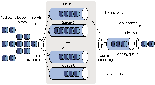
Figure 4-1 Diagram for SP queuing
SP queue-scheduling algorithm is specially designed for critical service applications. An important feature of critical services is that they demand preferential service in congestion in order to reduce the response delay. Assume that there are eight output queues on the port and the preferential queue classifies the eight output queues on the port into eight classes, which are queue7, queue6, queue5, queue4, queue3, queue2, queue1, and queue0. Their priorities decrease in order.
In queue scheduling, SP sends packets in the queue with higher priority strictly following the priority order from high to low. When the queue with higher priority is empty, packets in the queue with lower priority are sent. You can put critical service packets into the queues with higher priority and put non-critical service (such as e-mail) packets into the queues with lower priority. In this case, critical service packets are sent preferentially and non-critical service packets are sent when critical service groups are not sent.
The disadvantage of SP queue is that: if there are packets in the queues with higher priority for a long time in congestion, the packets in the queues with lower priority will be “starved” because they are not served.
2) WRR queue-scheduling algorithm
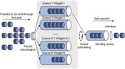
Figure 4-2 Diagram for WRR queuing
A port of the switch supports eight outbound queues. The WRR queue-scheduling algorithm schedules all the queues in turn to ensure that every queue can be assigned a certain service time. Assume there are eight output queues on the port. The eight weight values (namely, w 7, w 6, w 5, w 4, w 3, w 2, w 1, and w 0) indicating the proportion of assigned resources are assigned to the eight queues respectively. On a 100M port, you can configure the weight values of WRR queue-scheduling algorithm to 50, 30, 10, 10, 50, 30, 10, and 10 (corresponding to w7, w6, w5, w4, w3, w2, w1, and w0 respectively). In this way, the queue with the lowest priority can be assured of 5 Mbps of bandwidth at least, thus avoiding the disadvantage of SP queue-scheduling algorithm that packets in low-priority queues are possibly not to be served for a long time. Another advantage of WRR queue-scheduling algorithm is that though the queues are scheduled in turn, the service time for each queue is not fixed, that is to say, if a queue is empty, the next queue will be scheduled immediately. In this way, the bandwidth resources are fully utilized.
H3C S3610 and S5510 Series Ethernet Switches support the following three queue scheduling algorithms:
l All the queues are scheduled through the SP algorithm.
l All the queues are scheduled through the WRR algorithm.
l Some queues are scheduled through the SP algorithm, while other queues are scheduled through the WRR algorithm.
4.3 Configuring an SP Queue
Follow these steps to configure SP queues:
|
To do… |
Use the command… |
Remarks |
|
|
Enter system view |
system-view |
— |
|
|
Enter port view or port group view |
Enter port view |
interface interface-type interface-number |
Perform either of the two operations. The configuration performed in Ethernet port view applies to the current port only. The configuration performed in port group view applies to all the ports in the port group. |
|
Enter port group view |
port-group { manual port-group-name | aggregation agg-id } |
||
|
Configure SP queue scheduling algorithm |
undo qos wrr |
Optional By default, SP queue scheduling algorithm is adopted on all the ports. |
|
4.4 Configuring a WRR Queue
You can divide the outbound queues into WRR precedence queue group 1 and WRR precedence queue group 2. The SP scheduling algorithm is adopted for WRR groups. For example, queue 0, queue 1, queue 2, and queue 3 are in WRR group 1, and queue 4, queue 5, queue 6, and queue 7 are in group 2. Round robin is performed in WRR group 2 firstly. If no packet is to be sent in WRR group 2, round robin is performed in WRR group 1.
4.4.1 Configuration Procedure
Follow these steps to configure WRR queues:
|
To do… |
Use the command… |
Remarks |
|
|
Enter system view |
system-view |
— |
|
|
Enter port view or port group view |
Enter port view |
interface interface-type interface-number |
Perform either of the two operations. The configuration performed in Ethernet port view applies to the current port only. The configuration performed in port group view applies to all the ports in the port group |
|
Enter port group view |
port-group { manual port-group-name | aggregation agg-id } |
||
|
Adopt the WRR queue scheduling on the port |
qos wrr queue-id group group-id weight queue-weight |
Required By default, SP queue scheduling algorithm is adopted on all the ports. |
|
![]() Caution:
Caution:
With WRR queue scheduling algorithm adopted, the queues assigned to the same queue scheduling group must be with consecutive queue numbers.
4.4.2 Configuration Examples
I. Network requirements
l Configure queues on the port as WRR queues.
l Configure queue 0, queue 1, queue 2, and queue 3 to be in WRR group 1, with the weight being 10, 20, 50, and 70 respectively.
l Configure queue 4, queue 5, queue 6, and queue 7 to be in WRR group 2, with the weight being 20, 50, 70, and 100 respectively.
II. Configuration procedure
# Enter system view.
<Sysname> system-view
# Configure the WRR queues on Ethernet1/0/1 port.
[Sysname] interface Ethernet 1/0/1
[Sysname-Ethernet1/0/1] qos wrr 0 group 1 weight 1
[Sysname-Ethernet1/0/1] qos wrr 1 group 1 weight 2
[Sysname-Ethernet1/0/1] qos wrr 2 group 1 weight 4
[Sysname-Ethernet1/0/1] qos wrr 3 group 1 weight 6
[Sysname-Ethernet1/0/1] qos wrr 4 group 1 weight 8
[Sysname-Ethernet1/0/1] qos wrr 5 group 1 weight 10
[Sysname-Ethernet1/0/1] qos wrr 6 group 1 weight 12
[Sysname-Ethernet1/0/1] qos wrr 7 group 1 weight 14
4.5 Configuring SP+WRR Queues
As required, you can adopt SP queue scheduling algorithm for a part of the queues on a port, and meanwhile adopt WRR queue scheduling algorithm for another part of the queues on this port. In this way, the SP+WRR queue scheduling is enabled through adding queues on a port to SP queue scheduling groups and WRR queue scheduling groups respectively. SP queue scheduling algorithm is adopted between each group.
For example, queue 0 and queue 1 are in the SP queue scheduling group, and queue 2, queue 3, and queue 4 are in the WRR queue scheduling group 1, queue 5, queue 6, and queue 7 are in WRR queue scheduling group 2. Round robin is performed in WRR group 2 firstly. If no packet is to be sent in WRR group 2, round robin is performed in WRR group 1. At last, packets in the SP queue scheduling group are processed.
4.5.1 Configuration Procedure
Follow these steps to configure SP + WRR queues:
|
To do… |
Use the command… |
Remarks |
|
|
Enter system view |
system-view |
— |
|
|
Enter port view or port group view |
Enter port view |
interface interface-type interface-number |
Perform either of the two operations. The configuration performed in Ethernet port view applies to the current port only. The configuration performed in port group view applies to all the ports in the port group. |
|
Enter port group view |
port-group { manual port-group-name | aggregation agg-id } |
||
|
Configure SP queue scheduling |
qos wrr queue-id group sp |
Required |
|
|
Configure WRR queue scheduling |
qos wrr queue-id group group-id weight queue-weight |
Required |
|
![]() Caution:
Caution:
With SP + WRR queue scheduling algorithm adopted, the queues assigned to the same queue scheduling group must be with consecutive queue numbers.
4.5.2 Configuration Examples
I. Network requirements
l Configure to adopt SP+WRR queue scheduling algorithm on Ethernet1/0/1.
l Configure queue 0 and queue 1 on Ethernet1/0/1 to be in SP queue scheduling group.
l Configure queue 2, queue 3, and queue 4 on Ethernet 1/0/1 to be in WRR queue scheduling group 1, with the weight being 20, 70, and 100 respectively.
l Configure queue 5, queue 6, and queue 7 on Ethernet1/0/1 to be in WRR queue scheduling group 2, with the weight being 10, 50, and 80 respectively.
II. Configuration procedure
# Enter system view.
<Sysname> system-view
# Enable the SP+WRR queue scheduling algorithm on Ethernet1/0/1.
[Sysname] interface Ethernet 1/0/1
[Sysname-Ethernet1/0/1] qos wrr 0 group sp
[Sysname-Ethernet1/0/1] qos wrr 1 group sp
[Sysname-Ethernet1/0/1] qos wrr 2 group 1 weight 20
[Sysname-Ethernet1/0/1] qos wrr 3 group 1 weight 70
[Sysname-Ethernet1/0/1] qos wrr 4 group 1 weight 100
[Sysname-Ethernet1/0/1] qos wrr 5 group 2 weight 10
[Sysname-Ethernet1/0/1] qos wrr 6 group 2 weight 50
[Sysname-Ethernet1/0/1] qos wrr 7 group 2 weight 80
4.6 Displaying Congestion Management
|
To do… |
Use the command… |
Remarks |
|
Display WRR queue configuration information |
display qos wrr interface [ interface-type interface-number ] |
Available in any view |
Chapter 5 Priority Mapping
When configuring priority mapping, go to these sections for information you are interested in:
l Configuring a Priority Mapping Table
l Configuring the Port Priority
l Configuring Port Priority Trust Mode
5.1 Priority Mapping Overview
The local precedence and drop precedence are described as follows.
l Local precedence is the precedence that the switch assigns to a packet and it is corresponding to the number of an outbound queue on the port. Local precedence takes effect only on the local switch.
l Drop precedence is a parameter that is referred to when dropping packets. The higher the drop precedence, the more likely a packet is dropped.
For packets without 802.1q tags, the switch uses the priority of the receiving port as the 802.1p precedence of the received packets, and then obtains the local precedence of the received packets by mapping the 802.1p precedence.
For packets with 802.1q tags, the switch provides the following two priority trust modes:
l Trusting packet priority
The switch looks up the 802.1p precedence of the received packets in the 802.1p-precedence-to-local-precedence or 802.1p-precedence-to-drop-precedence mapping table for the corresponding local precedence or drop precedence and assigns the precedence to the received packets.
l Trusting port priority
The switch uses the priority of the receiving port as the 802.1p precedence of the received packets, looks up the 802.1p precedence in the 802.1p-precedence-to-local-precedence or 802.1p-precedence-to-drop-precedence mapping table for the corresponding local precedence or drop precedence, and then assigns the precedence to the received packets.
The default 802.1p precedence to local precedence/drop precedence mapping table is as shown below.
Table 5-1 The default values of dot1p-lp mapping table and dot1p-dp mapping table
|
Imported priority value |
dot1p-lp mapping |
dot1p-dp mapping |
|
802.1p priority (dot1p) |
Local precedence (lp) |
Drop precedence (dp) |
|
0 |
2 |
0 |
|
1 |
0 |
0 |
|
2 |
1 |
0 |
|
3 |
3 |
0 |
|
4 |
4 |
0 |
|
5 |
5 |
0 |
|
6 |
6 |
0 |
|
7 |
7 |
0 |
The switch also provides DSCP precedence to local/drop/802.1p/DSCP precedence mapping tables for the corresponding priority mapping. The default settings of these priority mapping tables are shown in Table 5-2. As for the right most four columns of the table,
l The dscp-lp mapping column lists the default target local precedence values, available only for IP packets.
l The dscp-dp mapping lists the default target drop precedence values, available only for IP packets.
l The dscp-dot1p mapping column lists the default target 802.1p precedence values, available only for IP packets.
l The dscp-dscp mapping column lists the default target DSCP precedence values, available only for IP packets.
Table 5-2 The default values of dscp-lp mapping, dscp-dp mapping, dscp-dot1p mapping, and dscp-dscp mapping
|
Imported priority value |
dscp-lp mapping |
dscp-dp mapping |
dscp-dot1p mapping |
dscp-dscp mapping |
|
DSCP precedence (dscp) |
Local precedence (lp) |
Drop precedence (dp) |
802.1p priority (dot1p) |
DSCP precedence (dscp) |
|
0 to 7 |
0 |
0 |
0 |
0 |
|
8 to 15 |
1 |
0 |
1 |
8 |
|
16 to 23 |
2 |
0 |
2 |
16 |
|
24 to 31 |
3 |
0 |
3 |
24 |
|
32 to 39 |
4 |
0 |
4 |
32 |
|
40 to 47 |
5 |
0 |
5 |
40 |
|
48 to 55 |
6 |
0 |
6 |
48 |
|
56 to 63 |
7 |
0 |
7 |
56 |
Note that:
l The 802.1p priority mapping table is associated with the priority trust mode on a port. The 802.p priority mapping table takes effect only when the 802.1p priorities carried in packets are trusted on ports. For information about configuring port priority trust modes, refer to 5.4 Configuring Port Priority Trust Mode.
l The DSCP priority mapping table is associated with the priority mapping action in traffic behavior. The priority mapping table takes effect only when the priority mapping action is configured in the associated traffic behavior specified by a policy. For the detailed information about configuring traffic behavior, refer to section 3.4.3 “Defining a Traffic Behavior”.
5.2 Configuring a Priority Mapping Table
You can modify the priority mapping tables in a switch as required.
Follow the two steps to configure priority mapping tables:
l Enter priority mapping table view;
l Configure priority mapping parameters.
5.2.1 Configuration Prerequisites
The new priority mapping table is determined.
5.2.2 Configuration Procedure
Follow these steps to configure a priority mapping table:
|
To do… |
Use the command… |
Remarks |
|
Enter system view |
system-view |
— |
|
Enter priority mapping table view |
qos map-table { dot1p-lp | dot1p-dp | dscp-lp | dscp-dp | dscp-dot1p | dscp-dscp } |
Required To configure a priority mapping table, you need to enter the corresponding priority mapping table view. |
|
Configure priority mapping parameters |
import import-value-list export export-value |
Required The newly configured mapping entries overwrite the corresponding previous entries. |
5.2.3 Configuration Examples
I. Network requirements
Modify the dot1p-lp mapping table as those listed in Table 5-3.
Table 5-3 The specified dot1p-lp mapping
|
802.1p priority |
Local precedence |
|
0 |
0 |
|
1 |
0 |
|
2 |
1 |
|
3 |
1 |
|
4 |
2 |
|
5 |
2 |
|
6 |
3 |
|
7 |
3 |
II. Configuration procedure
# Enter system view.
<Sysname> system-view
# Enter dot1p-lp priority mapping table view.
[Sysname] qos map-table dot1p-lp
# Modify dot1p-lp priority mapping parameters.
[Sysname-maptbl-dot1p-lp] import 0 1 export 0
[Sysname-maptbl-dot1p-lp] import 2 3 export 1
[Sysname-maptbl-dot1p-lp] import 4 5 export 2
[Sysname-maptbl-dot1p-lp] import 6 7 export 3
5.3 Configuring the Port Priority
By default, the switch uses the priority of the receiving port as the 802.1p precedence of the received packets, looks up the 802.1p precedence in the 802.1p-precedence-to-local-precedence mapping table for the corresponding local precedence, and assigns the local precedence to the received packets. The packets are then added to output queues of the port by their local precedence.
Port priority is in the range 0 to 7. You can set the port priority as required.
5.3.1 Configuration Prerequisites
The port priority of the port is determined.
5.3.2 Configuration Procedure
Follow these steps to configure port priority:
|
To do… |
Use the command… |
Remarks |
|
|
Enter system view |
system-view |
— |
|
|
Enter port view or port group view |
Enter port view |
interface interface-type interface-number |
Perform either of the two operations. The configuration performed in Ethernet port view applies to the current port only. The configuration performed in port group view applies to all the ports in the port group. |
|
Enter port group view |
port-group { manual port-group-name | aggregation agg-id } |
||
|
Configure port priority |
qos priority priority-value |
Required By default, the port priority is 0. |
|
5.3.3 Configuration Examples
I. Network requirements
Configure the port priority to 7.
II. Configuration procedure
# Enter system view.
<Sysname> system-view
# Configure port priority of Ethernet1/0/1.
[Sysname] interface Ethernet 1/0/1
[Sysname-Ethernet1/0/1] qos priority 7
5.4 Configuring Port Priority Trust Mode
You can configure the switch to trust the 802.1p precedence carried in the received packets instead of using the priority of the receiving port as the 802.1p precedence of the received packets.
5.4.1 Configuration Prerequisites
It is determined to trust the 802.1p precedence of received packets.
5.4.2 Configuration Procedure
Follow these steps to configure the port priority trust mode:
|
To do… |
Use the command… |
Remarks |
|
|
Enter system view |
system-view |
— |
|
|
Enter port view or port group view |
Enter port view |
interface interface-type interface-number |
Perform either of the two operations. The configuration performed in Ethernet port view applies to the current port only. The configuration performed in port group view applies to all the ports in the port group. |
|
Enter port group view |
port-group { manual port-group-name | aggregation agg-id } |
||
|
Configure to trust 802.1p priorities carried in the packets |
qos trust dot1p |
Required By default, port priority is trusted. |
|
5.4.3 Configuration Examples
I. Network requirements
Configure to trust 802.1p priorities carried in the packets.
II. Configuration procedure
# Enter system view.
<Sysname> system-view
# Enter port view.
[Sysname] interface Ethernet 1/0/1
[Sysname-Ethernet1/0/1]
# Configure to trust 802.1p priorities.
[Sysname-Ethernet1/0/1] qos trust dot1p
5.5 Displaying Priority Mapping
|
To do… |
Use the command… |
Remarks |
|
Display the information about a specified priority mapping table |
display qos map-table [ dot1p-lp | dot1p-dp | dscp-lp | dscp-dp | dscp-dot1p | dscp-dscp ] |
Available in any view |
|
Display the priority trust mode configured for a port |
display qos trust interface [ interface-type interface-number ] |
Chapter 6 Congestion Avoidance
6.1 Overview
Serious congestion will bring great impact to the network resources, so some measures must be taken to avoid congestion. As a type of flow control mechanism, congestion avoidance monitors the utilization of network resources (such as queues or buffer in the memory), and can drop packets when congestion deteriorates. In this way, the congestion avoidance mechanism adjusts the network traffic so as to solve the overloading problem in the network.
Compared to the port-to-port flow control, congestion avoidance controls more traffic loading in the switch. When the switch drops packets from the source end, it can still cooperate with the flow control actions (such as TCP flow control) on the source end so as to adjust the traffic in the whole network to a reasonable load status. The combination of packet drop policy and flow control mechanism on the source end can maximize throughput and utilization rate of the network and minimize packet loss and delay.
I. Traditional packet drop policy
Tail drop is adopted in the traditional packet drop policy. When a queue length reaches the maximum value, all the new packets are dropped.
This packet drop policy will result in global TCP synchronization. If the queue drops packets from multiple TCP connections simultaneously, these TCP connections will go into the state of congestion avoidance and slow startup to reduce and adjust traffic and then reach traffic peak in a certain future time. Such changes will cause the network traffic jitter repeatedly.
II. RED and WRED
When congestion is too serious, the switch can adopt the random early detection (RED) or weighted RED (WRED) algorithm to solve the problem of excessive congestion and avoid global TCP synchronization caused by the tail-drop algorithm.
In the RED algorithm, an upper limit and a lower limit are set for each queue, and it is stipulated that:
l When the queue length is smaller than the lower limit, packets are not dropped.
l When the queue length is bigger than the upper limit, all inbound packets all dropped.
l When the queue length is in the range of the upper limit and the lower limit, the inbound packets are dropped at random. In this case, a number is assigned to each inbound packet and then compared with the drop probability of the current queue. If the number is bigger than the drop probability, the inbound packet is dropped. The longer a queue is, the higher the drop probability is. However, there is a top drop probability.
Compared with the RED algorithm, the WRED algorithm generates precedence-based random numbers. It adopts IP precedence in determining drop policy and takes the benefits of high-precedence packets into consideration, so the drop probability is comparatively low.
In the RED and WRED algorithm, packets are dropped at random so that global TCP synchronization is avoided. When packets in a TCP connection are dropped and sent at a low rate, packets in other TCP connections are still sent at a high rate. In this way, packets in a part of connections are sent at a high rate in any case. Thus, the utilization rate of bandwidth is improved.
III. Queue length
In the following cases, you can increase the queue length to buffer more packets and improve packet forwarding performance:
l Network with dense broadcast or multicast traffic and large burst traffic
l Packets of high-speed links are forwarded through low-speed links, or packets received through multiple equal-rate interfaces at the same time are forwarded to one interface that is of the same rate.
By increasing the queue length, you can reduce the packet loss ratio and packet processing capability of the device in the cases mentioned above. Although increasing queue length improves the ability to process burst traffic, it reduces the ability of congestion avoidance.
6.2 Configuring WRED
6.2.1 Configuration Prerequisites
Prepare a network environment where congestion may occur.
6.2.2 Configuration Procedure
Follow these steps to configure WRED:
|
To do… |
Use the command… |
Remarks |
|
|
Enter system view |
system-view |
— |
|
|
Enter port view or port group view |
Enter port view |
interface interface-type interface-number |
Perform either of the two operations. The configuration performed in port view applies to the current port only. Configuration performed in port group view applies to all the ports in the port group. |
|
Enter port group view |
port-group { manual port-group-name | aggregation agg-id } |
||
|
Enable WRED |
qos wred enable |
Required |
|
6.2.3 Configuration Example
I. Network requirements
Enable WRED on Ethernet1/0/1.
II. Configuration procedure
# Enter system view.
<Sysname> system-view
# Enter port view.
[Sysname] interface Ethernet 1/0/1
# Enable WRED.
[Sysname-Ethernet1/0/1] qos wred enable
6.3 Configuring Queue Length
6.3.1 Configuration Prerequisites
The ports requiring this configuration and the intended queue length values for each queue are determined.
6.3.2 Configuration Procedure
Follow these steps to configure queue length:
|
To do… |
Use the command… |
Remarks |
|
Enter system view |
system-view |
— |
|
Enter port view |
interface interface-type interface-number |
— |
|
Configure queue length |
burst-traffic { queue queue-id length queue-length }&<1-8> |
Required |
6.3.3 Configuration Example
I. Network requirements
Set the queue length of queue 1 and queue 3 to 8 and 32 on Ethernet 1/0/1.
II. Configuration procedure
# Enter system view.
<Sysname> system-view
# Enter port view.
[Sysname] interface Ethernet 1/0/1
# Configure queue length.
[Sysname-Ethernet1/0/1] burst-traffic queue 1 length 8 queue 3 length 32
6.4 Displaying and Maintaining Congestion Avoidance
|
To do… |
Use the command… |
Remarks |
|
Display the configuration information and statistics information about WRED on the port |
display qos wred interface [ interface-type interface-number ] |
Available in any view |
|
Display the queue length configuration of a port |
display burst-traffic interface [ interface-type interface-number ] |
Chapter 7 Aggregation CAR Configuration
7.1 Aggregation CAR Overview
Aggregation CAR enables traffic policing on multiple ports using the same CAR. If an aggregation CAR is applied to multiple ports, the total traffic on these ports must be within the traffic policing range specified in the aggregation CAR.
& Note:
For the S5510 series Ethernet switches, if you apply the same aggregation CAR to any of the first 12 ports on the switch and any of the last 16 ports on a switch at the same time, the actual traffic limit may be twice the limit defined in the aggregation CAR.
7.2 Applying Aggregation CAR on Ports
7.2.1 Configuration Prerequisites
l Parameter values of the aggregation CAR are determined.
l Ports where aggregation CAR is applied are determined.
l Matching rules for traffic are determined on the ports. ACLs must be defined if ACL-based matching rules are used.
l Refer to the ACL module for details on ACL defining.
7.2.2 Configuration Procedure
Follow these steps to configure aggregation CAR:
|
To do… |
Use the command… |
Remarks |
|
Enter system view |
system-view |
— |
|
Configure parameters for CAR |
qos car global-car-name aggregative cir committed-information-rate [ cbs committed-burst-size [ ebs excess-burst-size ] ] [ pir peak-information-rate ] [ red action ] |
Required CBS is 100,000 bytes by default. EBS is 100,000 bytes by default. PIR is 0 by default. The default action for red packets is discard. |
7.3 Applying Aggregation CAR
7.3.1 Applying Aggregation CAR to a Port or a Port Group
I. Configuration Prerequisites
l Aggregation CAR-related parameters are determined.
l The port or port group to which aggregation CAR is to be applied is determined.
l ACL rules used for packet matching are determined. Refer to the ACL module in this manual for detailed configuration.
II. Configuration Procedure
Follow these steps to apply aggregation CAR to a port or port group:
|
To do… |
Use the command… |
Remarks |
|
|
Enter system view |
system-view |
— |
|
|
Enter port view or port group view |
Enter port view |
interface interface-type interface-number |
Perform either of the two operations. The configuration performed in port view applies to the current port only. Configuration performed in port group view applies to all the ports in the port group. |
|
Enter port group view |
port-group { manual port-group-name | aggregation agg-id } |
||
|
Apply aggregation CAR |
qos car inbound acl [ ipv6 ] acl-number name global-car-name |
Required |
|
III. Configuration Example
Apply aggregation CAR to Ethernet 1/0/1 and Ethernet 1/0/2 to set the maximum rate of incoming traffic matching IPv4 ACL 2001 on the two ports to 1000 kbps and drop the packets exceeding the specification.
Configuration procedure:
# Enter system view.
<Sysname> system-view
# Configure aggregation CAR aggcar-1.
[Sysname] qos car aggcar-1 aggregative cir 1000
# Apply the aggregation CAR aggcar-1 to the inbound direction of Ethernet 1/0/1 and Ethernet 1/0/2.
[Sysname] interface Ethernet 1/0/1
[Sysname-Ethernet1/0/1] qos car inbound acl 2001 name aggcar-1
[Sysname-Ethernet1/0/1] quit
[Sysname] interface Ethernet 1/0/2
[Sysname-Ethernet1/0/2] qos car inbound acl 2001 name aggcar-1
7.3.2 Referencing Aggregation CAR in a Traffic Behavior
I. Configuration Prerequisites
l Parameter values of the aggregation CAR are determined.
l Traffic behaviors where aggregation CAR is referenced are determined.
II. Configuration Procedure
Follow these steps to reference aggregation CAR in a traffic behavior:
|
To do… |
Use the command… |
Remarks |
|
Enter system view |
system-view |
— |
|
Enter traffic behavior view |
traffic behavior behavior-name |
Required |
|
Reference aggregation CAR in the traffic behavior |
car name global-car-name |
Required |
III. Configuration Example
Reference aggregation CAR aggcar-1 in the traffic behavior be1. The aggregation CAR aggcar-1 is configured with the following parameters: CIR is 200 kbps, CBS is 2000 bytes, and packets exceeding the traffic specification are dropped.
Configuration procedure:
# Enter system view.
<Sysname> system-view
# Configure aggregation CAR aggcar-1.
[Sysname] qos car aggcar-1 aggregative cir 200 cbs 2000
# Reference aggregation CAR aggcar-1 in the traffic behavior be1.
[Sysname] traffic behavior be1
[Sysname-behavior-be1] car name aggcar-1
7.4 Displaying and Maintaining Aggregation CAR
|
To do… |
Use the command… |
Remarks |
|
Clear the statistics information of the specified aggregation CAR |
reset qos car name [ global-car-name ] |
Available in user view |
|
Display the configuration information and statistics information about the specified aggregation CAR |
display qos car name global-car-name |
Available in any view |
Chapter 8 VLAN Policy Configuration
When configuring VLAN policy, go to these sections for information that you are interested in:
l Overview
l Displaying and Maintaining VLAN Policy
l VLAN Policy Configuration Examples
8.1 Overview
QoS polices support the following application modes:
l Port-based application: QoS policies are effective for inbound packets on a port.
l VLAN-based application: QoS policies are effective for inbound traffic on a VLAN.
VLAN-based QoS policies are also known as VLAN policies for short. VLAN policies can facilitate the application and management of QoS policies on the switch.
VLAN policies are not effective on dynamic VLANs. VLAN policies will not be applied to dynamic VLANs. For example, the device may create VLANs dynamically when GVRP protocol is running. In this case, the corresponding VLAN policies are not effective on dynamic VLANs.
& Note:
For S5510 series Ethernet switches, if you apply traffic policing configured in a QoS policy to a VLAN containing any of the first 12 ports and any of the last 16 ports on a switch at the same time, the actual traffic limit may be twice the configured traffic limit.
8.2 Applying VLAN Policy
8.2.1 Configuration Prerequisites
l The VLAN policy to be applied is defined. Refer to Configuring a QoS Policy for policy defining.
l VLANs where the VLAN policy is to be applied are determined.
8.2.2 Configuration Procedure
Follow these steps to apply VLAN policies:
|
To do… |
Use the command… |
Remarks |
|
Enter system view |
system-view |
— |
|
Apply the VLAN policy to specified VLANs |
qos vlan-policy policy-name vlan vlan-id-list inbound |
Required You can provide the vlan-id-list argument in the form of vlan-id to vlan-id or provide multiple VLAN IDs for the argument. Up to eight VLAN IDs are allowed. |
& Note:
The QoS policy applied to a port overrides the QoS policy applied to the VLAN the port belongs to.
8.3 Displaying and Maintaining VLAN Policy
|
To do… |
Use the command… |
Remarks |
|
Display the VLAN policy |
display qos vlan-policy { name policy-name | vlan [ vlan-id ] } |
Available in any view |
|
Clear the statistics information about the VLAN policy |
reset qos vlan-policy [ vlan vlan-id ] |
Available in user view |
8.4 VLAN Policy Configuration Examples
8.4.1 Network Requirements
l The VLAN policy named test is defined to perform traffic policing for the packets matching basic IPv4 ACL 2000, with CIR as 64 kbps.
l Apply the VLAN policy test to the inbound direction of VLAN 200, VLAN 300, VLAN 400, VLAN 500, VLAN 600, VLAN 700, VLAN 800, and VLAN 900.
8.4.2 Configuration Procedure
# Enter system view.
<Sysname> system-view
# Create a class and enter class view.
[Sysname] traffic classifier cl1
# Define a classification rule.
[Sysname-classifier-cl1] if-match acl 2000
[Sysname-classifier-cl1] quit
# Create a traffic behavior and enter traffic behavior view.
[Sysname] traffic behavior be1
# Configure the traffic behavior.
[Sysname-behavior-be1] car cir 64
[Sysname-behavior-be1] quit
# Create a QoS policy and enter QoS policy view.
[Sysname] qos policy test
# Associate a class with a traffic behavior.
[Sysname-qospolicy-test] classifier cl1 behavior be1
[Sysname-qospolicy-test] quit
# Apply the policy to specific VLANs.
[Sysname] qos vlan-policy test vlan 200 300 400 500 600 700 800 900 inbound
Chapter 9 Traffic Mirroring Configuration
When configuring traffic mirroring, go to these sections for information that you are interested in:
l Overview
l Configuring Traffic Mirroring
l Displaying Traffic Mirroring
l Traffic Mirroring Configuration Examples
9.1 Overview
Traffic mirroring is to replicate the specified packets to the specified destination. It is generally used for testing and troubleshooting the network. .
Depending on different types of mirroring destinations, there are three types of traffic mirroring:
l Mirroring to port: The desired traffic on a mirrored port is replicated and sent to a destination port (that is, a mirroring port).
l Mirroring to CPU: The desired traffic on a mirrored port is replicated and sent to the CPU on the board of the port for further analysis.
l Mirroring to VLAN: The desired traffic on a mirrored port is replicated and sent to a VLAN, where the traffic is broadcast and all the ports (if available) in the VLAN will receive the traffic. If the destination VLAN does not exist, you can still configure the function, and the function will automatically take effect after the VLAN is created and a port is added to it.
& Note:
Currently, H3C S3610 and S5510 Series Ethernet Switches only support traffic mirroring to port.
9.2 Configuring Traffic Mirroring
To configure traffic mirroring, you must enter the view of an existing traffic behavior.
Follow these steps to configure traffic mirroring to a port:
|
To do… |
Use the command… |
Remarks |
|
Enter system view |
system-view |
— |
|
Enter traffic behavior view |
traffic behavior behavior-name |
Required |
|
Configure traffic mirroring action in the traffic behavior |
mirror-to interface interface-type interface-number |
Required |
![]() Caution:
Caution:
l A member port in a port aggregation group cannot function as the destination port for traffic mirroring.
l If the destination port for traffic mirroring is not the same port as the destination port of the local port mirroring group, you cannot configure the two ports at the same time. For the detailed information about local port mirroring group, refer to the Port Mirroring module in this manual.
9.3 Displaying Traffic Mirroring
|
To do… |
Use the command… |
Remarks |
|
Display the configuration information about the user-defined traffic behavior |
display traffic behavior user-defined behavior-name |
Available in any view |
|
Display the configuration information about the user-defined policy |
display qos policy user-defined policy-name |
9.4 Traffic Mirroring Configuration Examples
9.4.1 Network Requirements
The user's network is as described below:
l Host A (with the IP address 192.168.0.1) and Host B are connected to Ethernet 1/0/1 of the switch.
l The data monitoring device is connected to Ethernet 1/0/2 of the switch.
It is required to monitor and analyze packets sent by Host A on the data monitoring device.
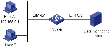
Figure 9-1 Network diagram for configuring traffic mirroring to a port
9.4.2 Configuration Procedure
Configure Switch:
# Enter system view.
<Sysname> system-view
# Configure basic IPv4 ACL 2000 to match packets with the source IP address 192.168.0.1.
[Sysname] acl number 2000
[Sysname-acl-basic-2000] rule permit source 192.168.0.1 0
[Sysname-acl-basic-2000] quit
# Configure a traffic classification rule to use ACL 2000 for traffic classification.
[Sysname] traffic classfier 1
[Sysname-classifier-1] if-match acl 2000
[Sysname-classifier-1] quit
# Configure a traffic behavior and define the action of mirroring traffic to Ethernet1/0/2 in the traffic behavior.
[Sysname] traffic behavior 1
[Sysname-behavior-1] mirror-to interface Ethernet 1/0/2
[Sysname-behavior-1] quit
# Configure a QoS policy and associate traffic behavior 1 with classification rule 1.
[Sysname] qos policy 1
[Sysname-policy-1] classifier 1 behavior 1
[Sysname-policy-1] quit
# Apply the policy in the inbound direction of Ethernet1/0/1.
[Sysname] interface Ethernet 1/0/1
[Sysname-Ethernet1/0/1] qos apply policy 1 inbound
After the configurations, you can monitor all packets sent from Host A on the data monitoring device.