- Table of Contents
-
- H3C S3610[S5510] Series Ethernet Switches Operation Manual-Release 5301-(V1.03)
- 00-1Cover
- 00-2Product Overview
- 01-Login Configuration
- 02-VLAN Configuration
- 03-IP Addressing and Performance Configuration
- 04-QinQ-BPDU Tunneling Configuration
- 05-Port Correlation Configuration
- 06-Link Aggregation Configuration
- 07-MAC Address Table Management Configuration
- 08-IP Source Guard Configuration
- 09-MSTP Configuration
- 10-IPv6 Configuration
- 11-Routing Overview
- 12-IPv4 Routing Configuration
- 13-BFD-GR Configuration
- 14-IPv6 Routing Configuration
- 15-Multicast Protocol Configuration
- 16-802.1x-HABP-MAC Authentication Configuration
- 17-AAA-RADIUS-HWTACACS Configuration
- 18-ARP Configuration
- 19-DHCP Configuration
- 20-ACL Configuration
- 21-QoS Configuration
- 22-Port Mirroring Configuration
- 23-Cluster Management Configuration
- 24-UDP Helper Configuration
- 25-SNMP-RMON Configuration
- 26-NTP Configuration
- 27-DNS Configuration
- 28-File System Management Configuration
- 29-Information Center Configuration
- 30-System Maintaining and Debugging Configuration
- 31-NQA Configuration
- 32-VRRP Configuration
- 33-SSH Configuration
- 34-MCE Configuration
- 35-OAM Configuration
- 36-DLDP Configuration
- 37-RRPP Configuration
- 38-SSL-HTTPS Configuration
- 39-PKI Configuration
- 40-Appendix
- Related Documents
-
| Title | Size | Download |
|---|---|---|
| 06-Link Aggregation Configuration | 98 KB |
Chapter 1 Link Aggregation Overview
1.1.2 Consistency Considerations for Ports in an Aggregation
1.2 Approaches to Link Aggregation
1.2.2 Static LACP link aggregation
1.3 Load Sharing in a Link Aggregation Group
Chapter 2 Link Aggregation Configuration
2.1 Configuring Link Aggregation
2.1.1 Configuring a Manual Link Aggregation Group
2.1.2 Configuring a Static LACP Link Aggregation Group
2.1.3 Configuring an Aggregation Group Name
2.1.4 Configuring a Service Loop Group
2.1.5 Entering Aggregation Port Group View
2.2 Displaying and Maintaining Link Aggregation
2.3 Link Aggregation Configuration Example
Chapter 1 Link Aggregation Overview
This chapter covers these topics:
l Approaches to Link Aggregation
l Load Sharing in a Link Aggregation Group
1.1 Link Aggregation
Link aggregation allows you to increase bandwidth by distributing incoming/outgoing traffic on the member ports in an aggregation group. In addition, it provides reliable connectivity because these member ports can dynamically back up each other.
1.1.1 LACP
Link Aggregation Control Protocol (LACP) is defined in IEEE 802.3ad. Link aggregation control protocol data unit (LACPDU) is used for exchanging information among LACP-enabled devices.
After LACP is enabled on a port, the port sends LACPDUs to notify the remote system of its system LACP priority, system MAC address, port LACP priority, port number, and operational key. Upon receipt of an LACPDU, the remote system compares the received information with the information received on other ports to determine the ports that can operate as selected ports. This allows the two systems to reach agreement on the states of the related ports
When aggregating ports, link aggregation control automatically assigns each port an operational key based on its rate, duplex mode, and other basic configurations. In an LACP aggregation group, all ports share the same operational key; in a manual or static LACP aggregation, the selected ports share the same operational key.
1.1.2 Consistency Considerations for Ports in an Aggregation
To participate in traffic sharing, member ports in an aggregation group must use the same configurations with respect to STP, QoS, GVRP, Q-in-Q, BPDU tunnel, VLAN, port attributes, MAC address learning, and so on as shown in the following table.
Table 1-1 Consistency considerations for ports in an aggregation
|
Category |
Considerations |
|
STP |
State of port-level STP (enabled or disabled) Attribute of the link (point-to-point or otherwise) connected to the port Port path cost STP priority Maximum transmission rate Loop protection Root protection Port type (whether the port is an edge port) |
|
QoS |
Traffic policing Traffic shaping Congestion avoidance Port rate limiting Strict priority (SP) queuing Weighted round robin (WRR) queuing Weighted fair queuing (WFQ) Port priority Port trust mode |
|
GVRP |
GVRP state on ports (enabled or disabled) GVRP registration type GARP timers |
|
Q-in-Q |
State of Q-in-Q (enabled or disabled) Added outer VLAN tag Policy of appending outer VLAN tag according to inner VLAN IDs |
|
BPDU tunnel |
BPDU tunnel state on ports (enabled or disabled) BPDU tunnel state for STP on ports (enabled or disabled) |
|
VLAN |
VLANs carried on the port Default VLAN ID on the port Link type of the port, which can be trunk, hybrid, or access sub-net VLAN configuration protocol VLAN configuration VLAN tag configuration |
|
Port attribute |
Port rate Duplex mode Up/down state of the link Isolation group membership of the port |
|
MAC address learning |
MAC address learning capability Setting of maximum number of MAC addresses that can be learned on the port Forwarding of frames with unknown destination MAC addresses after the upper limit of the MAC address table is reached |
1.2 Approaches to Link Aggregation
Two ways are available for implementing link aggregation, as described in Manual Link Aggregation and Static LACP link aggregation.
1.2.1 Manual Link Aggregation
I. Overview
Manual aggregations are created manually. Member ports in a manual aggregation are LACP-disabled.
II. Port states in a manual aggregation
In a manual aggregation group, ports are either selected or unselected. Selected ports can receive and transmit data frames whereas unselected ones cannot.
When setting the state of ports in a manual aggregation group, the system considers the following:
l The system selects the port with the highest priority in the up state as the reference port of the aggregation group. Port priority descends in the following order: full duplex/high speed, full duplex/low speed, half duplex/high speed, and half duplex/low speed. If multiple ports are of the same priority, the one with the lowest port number is the reference port.
l Ports in the up state with the same speed, duplex mode, link state, and basic configuration as the reference port become the candidates for selected ports, while the other ports become unselected ports.
l There is a limit on the number of selected ports in a manual aggregation group. If the number of selected-port candidates does not reach the limit, all the candidates become selected ports; if the number of candidates exceeds the limit, the candidates with lower port numbers become selected ports, while the other candidates become unselected ports.
l The selected port with the lowest port number serves as the master port of the aggregation group, and the other ports serve as the member ports of the aggregation group.
l If all the ports of an aggregations port are down, the port with the lowest port number is the master port. In this case, all of them are unselected ports.
In addition, unless the master port should be selected, a port that joins the group after the limit is reached will not be placed in selected state even if it should be in normal cases. This is to prevent the ongoing service on selected ports from being interrupted. You need to avoid the situation however as the selected/unselected state of a port may become different after a reboot.
III. Port Configuration Considerations in manual aggregation
As mentioned above, in a manual aggregation group, only ports with configurations consistent with those of the reference port can become selected. These configurations include port rate, duplex mode, link state, and other basic configurations, as described in Consistency Considerations for Ports in an Aggregation.
You need to maintain the basic configurations of these ports manually to ensure consistency. As one configuration change may involve multiple ports, this can become troublesome if you need to do that port by port. As a solution, you may add the ports into an aggregation port group where you can make configuration for all member ports.
When the configuration of some port in a manual aggregation group changes, the system does not remove the aggregation; instead, it re-sets the selected/unselected state of the member ports and re-selects a master port.
1.2.2 Static LACP link aggregation
I. Overview
Static aggregations are created manually. After you add a port to a static aggregation, LACP is enabled on it automatically.
II. Port states in static aggregation
In a static aggregation group, ports can be selected or unselected, where both can receive and transmit LACPDUs but only selected ports can receive and transmit data frames.
When setting the state of the ports in the local and remote static aggregation groups, the local and remote systems do the following:
1) Compare their system IDs to identify the higher priority system. (The system ID comprises LACP priority and system MAC address.)
l First compare the system LACP priorities. The system with lower system LACP priority wins out.
l If the system LACP priorities are the same, compare the system MAC addresses. The system with the smaller MAC address wins out.
2) Compare the port IDs on the higher priority system. (The port ID comprises port LACP priority and port number.)
l Compare the port LACP priorities. The port with lower port LACP priority wins out.
l If two ports with the same port LACP priority are present, compare their port numbers. The one with the smaller port ID wins out to become the reference port.
3) Select the candidates for selected ports. To be a candidate, a port must be in the up state with the same speed, duplex mode, link state, and basic configuration as the reference port; in addition, their peer ports on the other system must have the same configuration. All the ports but the selected-port candidates become unselected.
4) As there is a limit on the number of selected ports, not all selected-port candidates can become selected ports. Before the limit is reached, all the candidates are set to the selected state. When the limit is reached, the candidates with lower port numbers are set to the selected state while the other candidates are set to the unselected state. At the same time, the other system gets aware of the state change of the ports on the higher priority system and thus sets the state of the corresponding local ports.
5) Set the selected port with the lowest port number as the master port in the aggregation group on each system.
III. Port configuration considerations in static aggregation
Like in a manual aggregation group, in a static LACP aggregation group, only ports with configurations consistent with those of the reference port can become selected. These configurations include port rate, duplex mode, link state and other basic configurations described in Consistency Considerations for Ports in an Aggregation.
You need to maintain the basic configurations of these ports manually to ensure consistency. As one configuration change may involve multiple ports, this can become troublesome if you need to do that port by port. As a solution, you may add the ports into an aggregation port group where you can make configuration for all member ports.
When the configuration of some port in a static aggregation group changes, the system does not remove the aggregation; instead, it re-sets the selected/unselected state of the member ports and re-selects a master port.
1.3 Load Sharing in a Link Aggregation Group
A link aggregation group can be load sharing or non-load sharing, depending on the availability of aggregation resources when the group is created.
l When aggregation resources are available, the group is a load sharing aggregation group if it contains selected port(s).
l If all aggregation resources are used up, the group is a non-load sharing aggregation group.
With load sharing enabled, traffic is distributed on the selected ports in the aggregation group. However, the way of selecting forwarding ports varies by packet type:
l For a known Layer 2 unicast packet, the switch selects the forwarding port based on the least significant six bits in the source MAC address and the least significant six bits in the destination MAC address.
l For a unicast IP packet with the destination MAC address being known, the switch selects the forwarding port based on the lower order 6 bits in the source MAC address, the lower order 6 bits in the destination MAC address, the lower order 6 bits in the source IP address, the lower order bits 16 through 21 in the source IP address, the lower order 6 bits in the destination IP address, and the lower order bits 16 through 21 in the destination IP address.
l For a broadcast/multicast/unknown unicast packet, the switch selects the forwarding port based on its VLAN ID, source port ID, and source device ID.
![]() Caution:
Caution:
The arrived broadcasts/multicasts/unknown unicasts may be distributed over different selected ports if they have different VLAN IDs, source ports, or source devices; if they are only different in source MAC address, they are forwarded out the same port.
1.4 Service Loop Group
You can create a service loop group by creating a manual aggregation group of service-loop ports first and then specifying which services can be redirected for the group. At present, you may specify to redirect four types of services, IPv6 (IPv6 unicast), IPv6mc (IPv6 multicast), tunnel, and MPLS.
& Note:
Currently, the S3610&S5510 series Ethernet switches support to redirect tunnel services only.
After creating a service-loop group, assign ports that support its service type to the group considering the following:
l These ports can be configured only with the physical configuration such as speed and duplex mode, QoS, and ACL. Other conflicting configurations, such as STP cannot be configured.
l These ports must belong to VLAN 1.
After assigning a port to a service-loop group, you may configure it with other non-conflicting settings, such as QoS.
If this group is performing load sharing, it continues to function in this way even after all selected ports but one are removed to ensure ongoing service.
1.5 Aggregation Port Group
As mentioned earlier, in a manual or static aggregation group, a port can be selected only when its configuration is the same as that of the reference port in terms of duplex/speed pair, link state, and other basic configurations. Their configuration consistency requires administrative maintenance, which is troublesome after you change some configuration.
To simplify configuration, port-groups are provided allowing you to configure for all ports in individual groups at one time. One example of port-groups is aggregation port group.
Upon creation or removal of a link aggregation group, an aggregation port-group which cannot be administratively created or removed is automatically created or removed. In addition, you can only assign/remove a member port to/from an aggregation port-group by assigning/removing it from the corresponding link aggregation group.
For more information about port-groups, refer to Port Correlation Configuration.
Chapter 2 Link Aggregation Configuration
When configuring link aggregation, go to these sections for information you are interested in:
l Configuring Link Aggregation
l Displaying and Maintaining Link Aggregation
l Link Aggregation Configuration Example
2.1 Configuring Link Aggregation
This section covers these topics:
l Configuring a Manual Link Aggregation Group
l Configuring a Static LACP Link Aggregation Group
l Configuring an Aggregation Group Name
l Configuring a Service Loop Group
l Entering Aggregation Port Group View
2.1.1 Configuring a Manual Link Aggregation Group
Follow these steps to create a manual aggregation group and add an Ethernet port to it:
|
To do… |
Use the command… |
Remarks |
|
Enter system view |
system-view |
–– |
|
Create a manual aggregation group |
link-aggregation group agg-id mode manual |
Required |
|
Enter Ethernet port view |
interface interface-type interface-number |
–– |
|
Assign the Ethernet port to the aggregation group |
port link-aggregation group agg-id |
Required |
Note that:
l You can create a manual aggregation group by changing the type of an existing static aggregation group. When you create a manual aggregation group in this way and the static aggregation group contains ports, LACP is disabled on the ports after the manual aggregation group is created.
l An aggregation group cannot contain the following ports: RRPP-enabled ports, reflector ports or destination ports of port mirroring groups, ports with static MAC addresses or black hole MAC addresses configured, voice VLAN-enabled ports, or 802.1x-enabled ports.
l After you remove a manual aggregation group, all the ports in the group are dismissed from it.
l For a manual aggregation group containing only one port, the only way to remove the port from it is to remove the aggregation group.
l To make an aggregation group function properly, make sure that the selected/unselected state of the ports at both ends of a link is consistent.
2.1.2 Configuring a Static LACP Link Aggregation Group
Follow these steps to configure a static aggregation group:
|
To do… |
Use the command… |
Remarks |
|
Enter system view |
system-view |
–– |
|
Configure the system LACP priority |
lacp system-priority system-priority |
Optional 32768 by default. Changing system LACP priority can affect the selected/unselected state of the ports in the group. |
|
Create a static LACP aggregation group |
link-aggregation group agg-id mode static |
Required |
|
Enter Ethernet port view |
interface interface-type interface-number |
–– |
|
Configure the port LACP priority |
lacp port-priority port-priority |
Optional 32768 by default. Changing port LACP priority can affect the selected/unselected state of the ports in the group. |
|
Assign the Ethernet port to the aggregation group |
port link-aggregation group agg-id |
Required |
Note that:
l You can create a static aggregation group by changing the type of an existing manual link aggregation group that contains no port.
l An aggregation group cannot contain the following ports: RRPP-enabled ports, reflector ports or destination ports of port mirroring groups, ports configured with static MAC addresses or black hole MAC addresses, voice VLAN-enabled ports, or 802.1x-enabled ports.
l After you remove a static aggregation group, all the ports in the group are dismissed from it, and LACP is disabled on the ports.
l For a static LACP aggregation group containing only one port, the only way to remove the port from the aggregation group is to remove the aggregation group.
& Note:
When making configuration, be aware that after a load-balancing aggregation group changes to a non-load balancing group due to resources exhaustion, either of the following may happen:
l Forwarding anomaly resulted from inconsistency of the two ends in the number of selected ports.
l Some protocols such as GVRP malfunction because the state of the remote port connected to the master port is unselected.
2.1.3 Configuring an Aggregation Group Name
Follow these steps to configure a name for an aggregation group:
|
To do… |
Use the command… |
Remarks |
|
Enter system view |
system-view |
–– |
|
Configure a name for a link aggregation group |
link-aggregation group agg-id description agg-name |
Required None is configured by default. |
2.1.4 Configuring a Service Loop Group
Follow these steps to configure a service loop group:
|
To do… |
Use the command… |
Remarks |
|
Enter system view |
system-view |
–– |
|
Create a manual aggregation group |
link-aggregation group agg-id mode manual |
Required |
|
Specify the aggregation group as a service loop group that is of specific type |
link-aggregation group agg-id service-type tunnel |
Required |
|
Enter Ethernet port view |
interface interface-type interface-number |
–– |
|
Add the Ethernet port to the aggregation group |
port link-aggregation group agg-id |
Required |
& Note:
l You can remove any service loop group except those that are currently referenced by modules.
l For a service loop group containing only one port, the only way to remove the port from it is to remove the service loop group.
2.1.5 Entering Aggregation Port Group View
In aggregation port group view, you can make configuration for all the member ports in a link aggregation group at one time.
Follow these steps to enter aggregation port group view:
|
To do… |
Use the command… |
Remarks |
|
Enter system view |
system-view |
–– |
|
Enter aggregation port group view |
port-group aggregation agg-id |
–– |
![]() Caution:
Caution:
In aggregation port group view, you can configure aggregation related settings such as STP, VLAN, QoS, GVRP, Q-in-Q, BPDU tunnel, MAC address learning, but cannot add or remove member ports.
2.2 Displaying and Maintaining Link Aggregation
|
To do… |
Use the command… |
Remarks |
|
Display the local system ID |
display lacp system-id |
Available in any view |
|
Display detailed information about link aggregation for the specified port or ports |
display link-aggregation interface interface-type interface-number [ to interface-type interface-number ] |
Available in any view |
|
Display information about the specified or all service loop groups |
display link-aggregation service-type [ agg-id ] |
Available in any view |
|
Display summaries for all link aggregation groups |
display link-aggregation summary |
Available in any view |
|
Display detailed information about specified or all link aggregation groups |
display link-aggregation verbose [ agg-id ] |
Available in any view |
|
Clear the statistics about LACP for specified or all ports |
reset lacp statistics [ interface interface-type interface-number [ to interface-type interface-number ] ] |
Available in user view |
2.3 Link Aggregation Configuration Example
I. Network requirements
Device A aggregates ports Ethernet 1/0/1 through Ethernet 1/0/3 to form one link connected to Device B and performs load sharing among these ports.
Create a tunnel service-loop group and add port Ethernet 1/0/1 to the group.
II. Network diagram
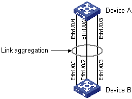
Figure 2-1 Network diagram for link aggregation configuration
III. Configuration procedure
& Note:
This example only describes how to configure link aggregation on Device A. To achieve link aggregation, do the same on Device B.
1) In manual aggregation approach
# Create manual aggregation group 1.
<DeviceA> system-view
[DeviceA] link-aggregation group 1 mode manual
# Add ports Ethernet 1/0/1 through Ethernet 1/0/3 to the group.
[DeviceA] interface ethernet 1/0/1
[DeviceA-Ethernet1/0/1] port link-aggregation group 1
[DeviceA-Ethernet1/0/1] interface ethernet 1/0/2
[DeviceA-Ethernet1/0/2] port link-aggregation group 1
[DeviceA-Ethernet1/0/2] interface ethernet 1/0/3
[DeviceA-Ethernet1/0/3] port link-aggregation group 1
2) In static aggregation approach
# Create static aggregation group 1.
<DeviceA> system-view
[DeviceA] link-aggregation group 1 mode static
# Add ports Ethernet 1/0/1 through Ethernet 1/0/3 to the group.
[DeviceA] interface ethernet 1/0/1
[DeviceA-Ethernet1/0/1] port link-aggregation group 1
[DeviceA-Ethernet1/0/1] interface ethernet 1/0/2
[DeviceA-Ethernet1/0/2] port link-aggregation group 1
[DeviceA-Ethernet1/0/2] interface ethernet 1/0/3
[DeviceA-Ethernet1/0/3] port link-aggregation group 1
3) Configure a service loop group
# Create a manual aggregation group.
<DeviceA> system-view
[DeviceA] link-aggregation group 1 mode manual
# Specify this group to be a tunnel service loop group.
[DeviceA] link-aggregation group 1 service-type tunnel
# Assign port Ethernet 1/0/1 to the service loop group.
[DeviceA] interface ethernet 1/0/1
[DeviceA-Ethernet1/0/1] undo stp
[DeviceA-Ethernet1/0/1] port link-aggregation group 1