- Table of Contents
-
- H3C S3610[S5510] Series Ethernet Switches Operation Manual-Release 5301-(V1.03)
- 00-1Cover
- 00-2Product Overview
- 01-Login Configuration
- 02-VLAN Configuration
- 03-IP Addressing and Performance Configuration
- 04-QinQ-BPDU Tunneling Configuration
- 05-Port Correlation Configuration
- 06-Link Aggregation Configuration
- 07-MAC Address Table Management Configuration
- 08-IP Source Guard Configuration
- 09-MSTP Configuration
- 10-IPv6 Configuration
- 11-Routing Overview
- 12-IPv4 Routing Configuration
- 13-BFD-GR Configuration
- 14-IPv6 Routing Configuration
- 15-Multicast Protocol Configuration
- 16-802.1x-HABP-MAC Authentication Configuration
- 17-AAA-RADIUS-HWTACACS Configuration
- 18-ARP Configuration
- 19-DHCP Configuration
- 20-ACL Configuration
- 21-QoS Configuration
- 22-Port Mirroring Configuration
- 23-Cluster Management Configuration
- 24-UDP Helper Configuration
- 25-SNMP-RMON Configuration
- 26-NTP Configuration
- 27-DNS Configuration
- 28-File System Management Configuration
- 29-Information Center Configuration
- 30-System Maintaining and Debugging Configuration
- 31-NQA Configuration
- 32-VRRP Configuration
- 33-SSH Configuration
- 34-MCE Configuration
- 35-OAM Configuration
- 36-DLDP Configuration
- 37-RRPP Configuration
- 38-SSL-HTTPS Configuration
- 39-PKI Configuration
- 40-Appendix
- Related Documents
-
| Title | Size | Download |
|---|---|---|
| 20-ACL Configuration | 231 KB |
Table of Contents
1.1.2 Application of ACLs on the Switch
1.2.4 IP Fragments Filtering with IPv4 ACL
Chapter 2 IPv4 ACL Configuration
2.2 Configuring a Basic IPv4 ACL
2.2.1 Configuration Prerequisites
2.3 Configuring an Advanced IPv4 ACL
2.3.1 Configuration Prerequisites
2.4 Configuring an Ethernet Frame Header ACL
2.4.1 Configuration Prerequisites
2.5 Configuring a User-Defined ACL
2.5.1 Configuration Prerequisites
2.6.1 Configuration Prerequisites
2.7 Displaying and Maintaining IPv4 ACLs
2.8 IPv4 ACL Configuration Example
Chapter 3 IPv6 ACL Configuration
3.2 Configuring a Basic IPv6 ACL
3.2.1 Configuration Prerequisites
3.3 Configuring an Advanced IPv6 ACL
3.3.1 Configuration Prerequisites
3.4.1 Configuration Prerequisites
3.5 Displaying and Maintaining IPv6 ACLs
3.6 IPv6 ACL Configuration Example
Chapter 4 Flow Template Configuration
4.2 Configuring a Flow Template
4.4 Flow Template Configuration Example
Chapter 1 ACL Overview
In order to filter traffic, network devices use sets of rules, called access control lists (ACLs), to identify and handle packets.
When configuring ACLs, go to these chapters for information you are interested in:
& Note:
Unless otherwise stated, ACLs refer to both IPv4 ACLs and IPv6 ACLs throughout this document.
1.1 Introduction to ACL
1.1.1 Introduction
As network scale and network traffic are increasingly growing, network security and bandwidth allocation become more and more critical to network management. Packet filtering can be used to efficiently prevent illegal users from accessing networks and to control network traffic and save network resources. Access control lists (ACL) are often used to filter packets with configured matching rules.
ACLs are sets of rules (or sets of permit or deny statements) that decide what packets can pass and what should be rejected based on matching criteria such as source MAC address, destination MAC address, source IP address, destination IP address, and port number.
1.1.2 Application of ACLs on the Switch
The switch supports two ACL application modes:
l Hardware-based application: An ACL is assigned to a piece of hardware. For example, an ACL can be referenced by QoS for traffic classification. Note that when an ACL is referenced to implement QoS, the actions defined in the ACL rules, deny or permit, do not take effect; actions to be taken on packets matching the ACL depend on the traffic behavior definition in QoS. For details about traffic behavior, refer to the QoS part in this manual.
l Software-based application: An ACL is referenced by a piece of upper layer software. For example, an ACL can be referenced to configure login user control behavior, thus controlling Telnet, SNMP and Web users. Note that when an ACL is reference by the upper layer software, actions to be taken on packets matching the ACL depend on those defined by the ACL rules. For details about login user control, refer to the part about login configuration in this manual.
& Note:
l When an ACL is assigned to a piece of hardware and referenced by a QoS policy for traffic classification, the device does not take action according to the traffic behavior definition on a packet that does not match the ACL.
l When an ACL is referenced by a piece of software to control Telnet, SNMP, and Web login users, the device denies all packets that do not match the ACL.
1.2 IPv4 ACL
This section covers these topics:
l IP Fragments Filtering with IPv4 ACL
1.2.1 IPv4 ACL Classification
IPv4 ACLs, identified by ACL numbers, fall into the following four categories:
l Basic IPv4 ACL, based on source IP address. Basic ACLs are numbered 2000 through 2999.
l Advanced IPv4 ACL, based on source IP address, destination IP address, protocol carried on IP, and other Layer 3 or Layer 4 protocol header information. Advanced ACLs are numbered 3000 through 3999.
l Ethernet frame header ACL, based on Layer 2 protocol header fields such as source MAC address, destination MAC address, 802.1p priority, and link layer protocol type. Ethernet frame header ACLs are numbered 4000 through 4999.
l User-defined ACL, based on customized information. By defining a user-defined ACL, you can specify which bytes starting from the Layer 2 header or IP header should match the user-defined string. User-defined ACLs are numbered 5000 through 5999.
1.2.2 IPv4 ACL Naming
When creating an IPv4 ACL, you can specify a unique name for it. Afterwards, you can identify the ACL by its name.
An IPv4 ACL can have only one name. Whether to specify a name for an ACL is up to you. After creating an ACL, you cannot specify a name for it, nor can you change or remove the name of the ACL.
& Note:
The name of an IPv4 ACL must be unique among IPv4 ACLs. However, an IPv4 ACL and an IPv6 ACL can share the same name.
1.2.3 IPv4 ACL Match Order
Each ACL is a sequential collection of rules defined with different matching criteria. The order in which a packet is matched against the rules may affect how the packet is handled.
At present, the following two match orders are available:
l config: where packets are compared against ACL rules in the order in which they are configured.
l auto: where depth-first match is performed. The term depth-first match has different meanings for different types of ACLs.
I. Depth-first match for a basic IPv4 ACL
The following shows how your device performs depth-first match in a basic IPv4 ACL:
1) Sort rules by source IP address wildcard first and compare packets against the rule configured with more zeros in the source IP address wildcard prior to other rules.
2) If two rules are present with the same number of zeros in their source IP address wildcards, compare packets against the rule configured first prior to the other.
II. Depth-first match for an advanced IPv4 ACL
The following shows how your device performs depth-first match in an advanced IPv4 ACL:
1) Sort rules by VPN instance first and compare packets against the rule configured with a VPN instance prior to other rules.
2) If two rules are present with VPN instances, look at the protocol range in addition. Then compare packets against the rule with the protocol carried on IP specified prior to the other.
3) If the protocol ranges are the same, look at source IP address wildcard. Then, compare packets against the rule configured with more zeros in the source IP address wildcard prior to the other.
4) If the numbers of zeros in the source IP address wildcards are the same, look at the destination IP address wildcards. Then, compare packets against the rule configured with more zeros in the destination IP address wildcard prior to the other.
5) If the numbers of zeros in the destination IP address wildcards are the same, look at the Layer 4 port number (TCP/UDP port number). Then compare packets against the rule configured with the lower port number prior to the other.
6) If the port numbers are the same, compare packets against the rule configured first prior to the other.
III. Depth-first match for an Ethernet frame header ACL
The following shows how your device performs depth-first match in an Ethernet frame header ACL:
1) Sort rules by source MAC address mask first and compare packets against the rule configured with more ones in the source MAC address mask prior to other rules.
2) If two rules are present with the same number of ones in their source MAC address masks, look at the destination MAC address masks. Then, compare packets against the rule configured with more ones in the destination MAC address mask prior to the other.
3) If the numbers of ones in the destination MAC address masks are the same, the one configured first is compared prior to the other.
& Note:
The match order for a user-defined ACL can only be config.
The comparison of a packet against an ACL stops once a match is found. The packet is then processed as per the rule.
1.2.4 IP Fragments Filtering with IPv4 ACL
Traditional packet filtering does not perform match operation on all IP fragments but first ones. All subsequent non-first fragments are handled the way the first fragments are handled. This causes security risk as attackers may fabricate non-first fragments to attack your network.
ACL rules configured with the fragment keyword apply to non-tail fragments only, and they do not apply to non-fragmented packets and tail fragments, while those configured without the keyword apply to both fragmented and non-fragmented packets.
1.3 IPv6 ACL
This section covers these topics:
1.3.1 IPv6 ACL Classification
IPv6 ACLs, identified by ACL numbers, fall into the following two categories:
l Basic IPv6 ACL, based on source IPv6 address. Basic IPv6 ACLs are numbered 2000 through 2999.
l Advanced IPv6 ACL, based on source IPv6 address, destination IPv6 address, protocol carried on IPv6, and other Layer 3 or Layer 4 protocol header fields. Advanced ACLs are numbered 3000 through 3999.
1.3.2 IPv6 ACL Naming
When creating an IPv6 ACL, you can specify a unique name for it. Afterwards, you can identify the IPv6 ACL by its name.
An IPv6 ACL can have only one name. Whether to specify a name for an ACL is up to you. After creating an ACL, you cannot specify a name for it, nor can you change or remove the name of the ACL.
& Note:
The name of an IPv6 ACL must be unique among IPv6 ACLs. However, an IPv6 ACL and an IPv4 ACL can share the same name.
1.3.3 IPv6 ACL Match Order
Similar to IPv4 ACLs, IPv6 ACLs are sequential collections of rules defined with different matching parameters. The order in which a packet is matched against the rules in an IPv6 ACL may affect how the packet is handled.
Like in IPv4 ACLs, the following two match orders are available in IPv6 ACLs:
l config: where rules are compared against in the order in which they are configured.
l auto: where depth-first match is performed.
I. Depth-first match for a basic IPv6 ACL
The following shows how your device performs depth-first match in a basic IPv6 ACL:
1) Sort rules by source IPv6 address wildcard first and compare packets against the rule configured with a longer prefix in the source IPv6 address wildcard prior to other rules.
2) If two rules are present with the same prefix length in their source IPv6 address wildcards, compare packets against the rule configured first prior to the other.
II. Depth-first match for an advanced IPv6 ACL
The following shows how your device performs depth-first match in an advanced IPv6 ACL:
1) Sort rules by protocol range first, and compare packets against the rule with the protocol carried on IPv6 specified prior to other rules.
2) If two rules are present with the same protocol range, look at source IPv6 address wildcard in addition. Then, compare packets against the rule configured with a larger prefix length in the source IPv6 address wildcard prior to the other.
3) If the prefix lengths in the source IPv6 address wildcards are the same, look at the destination IPv6 address wildcards. Then, compare packets against the rule configured with a larger prefix length in the destination IPv6 address wildcard prior to the other.
4) If the prefix lengths in the destination IPv6 address wildcards are the same, look at the Layer 4 port number (TCP/UDP port number). Then compare packets against the rule configured with the lower port number prior to the other.
5) If the port numbers are the same, compare packets against the rule configured first prior to the other.
The comparison of a packet against an ACL stops once a match is found. The packet is then processed as per the rule.
Chapter 2 IPv4 ACL Configuration
When configuring an IPv4 ACL, go to these sections for information you are interested in:
l Configuring a Basic IPv4 ACL
l Configuring an Advanced IPv4 ACL
l Configuring an Ethernet Frame Header ACL
l Configuring a User-Defined ACL
l Displaying and Maintaining IPv4 ACLs
l IPv4 ACL Configuration Example
2.1 Creating a Time Range
You can specify a time range for each rule in an ACL. A time range-based ACL takes effect only in specified time ranges. Only after a time range is configured and the system time is within the time range, can an ACL rule take effect.
Two types of time ranges are available:
l Periodic time range, which recurs periodically on the day or days of the week.
l Absolute time range, which takes effect only in a period of time and does not recur.
2.1.1 Configuration Procedure
Follow these steps to create a time range:
|
To do… |
Use the command… |
Remarks |
|
Enter system view |
system-view |
–– |
|
Create a time range |
time-range time-name { start-time to end-time days [ from time1 date1 ] [ to time2 date2 ] | from time1 date1 [ to time2 date2 ] | to time2 date2 } |
Required |
|
Display the configuration and state of a specified or all time ranges |
display time-range { time-name | all } |
Optional Available in any view |
Note that:
l Periodic time range created using the time-range time-name start-time to end-time days command. A time range thus created recurs periodically on the day or days of the week.
l Absolute time range created using the time-range time-name { from time1 date1 [ to time2 date2 ] | to time2 date2 } command. Unlike a periodic time range, a time range thus created does not recur. For example, to create an absolute time range that is active between January 1, 2004 00:00 and December 31, 2004 23:59, you may use the time-range test from 00:00 01/01/2004 to 23:59 12/31/2004 command.
l Compound time range created using the time-range time-name start-time to end-time days { from time1 date1 [ to time2 date2 ] | to time2 date2 } command. A time range thus created recurs on the day or days of the week only within the specified period. For example, to create a time range that is active from 12:00 to 14:00 on Wednesdays between January 1, 2004 00:00 and December 31, 2004 23:59, you may use the time-range test 12:00 to 14:00 wednesday from 00:00 01/01/2004 to 23:59 12/31/2004 command.
l You may create individual time ranges identified with the same name. They are regarded as one time range whose active period is the result of ORing periodic ones, ORing absolute ones, and ANDing periodic and absolute ones.
l With no start time specified, the time range is from the earliest time that the system can express (that is, 00:00 01/01/1970) to the end time. With no end time specified, the time range is from the time the configuration takes effect to the latest time that the system can express (that is, 24:00 12/31/2100).
l Up to 256 time ranges can be defined.
2.1.2 Configuration Examples
# Create a periodic time range that is active from 8:00 to 18:00 every working day.
<Sysname> system-view
[Sysname] time-range test 8:00 to 18:00 working-day
[Sysname] display time-range test
Current time is 22:17:42 1/5/2006 Thursday
Time-range : test ( Inactive )
08:00 to 18:00 working-day
# Create an absolute time range from 15:00, Jan 28, 2006 to 15:00, Jan 28, 2008.
<Sysname> system-view
[Sysname] time-range test from 15:00 1/28/2006 to 15:00 1/28/2008
[Sysname] display time-range test
Current time is 22:20:18 1/5/2006 Thursday
Time-range : test ( Inactive )
from 15:00 1/28/2006 to 15:00 1/28/2008
2.2 Configuring a Basic IPv4 ACL
Basic IPv4 ACLs filter packets based on source IP address. They are numbered in the range 2000 to 2999.
2.2.1 Configuration Prerequisites
If you want to reference a time range to a rule, define it with the time-range command first.
2.2.2 Configuration Procedure
Follow these steps to configure a basic IPv4 ACL:
|
To do… |
Use the command… |
Remarks |
|
Enter system view |
system-view |
–– |
|
Create and enter basic IPv4 ACL view |
acl number acl-number [ name acl-name ] [ match-order { auto | config } ] |
Required The default match order is config. If you specify a name for an IPv4 ACL when creating the ACL, you can use the acl name acl-name command to enter the view of the ACL later. |
|
Create or modify a rule |
rule [ rule-id ] { deny | permit } [ fragment | logging | source { sour-addr sour-wildcard | any } | time-range time-name ] * |
Required To create multiple rules, repeat this step. |
|
Set a rule numbering step |
step step-value |
Optional The default step is 5. |
|
Create an IPv4 ACL description |
description text |
Optional By default, no IPv4 ACL description is present. |
|
Create a rule description |
rule rule-id comment text |
Optional By default, no rule description is present. |
Note that:
l You will fail to create or modify a rule if its permit/deny statement is exactly the same as another rule. In addition, if the ACL match order is set to auto rather than config, you cannot modify ACL rules.
l When defining ACL rules, you need not always assign them IDs. The system can automatically assign rule IDs starting with 0 and increasing in certain rule numbering steps. A rule ID thus assigned is greater than the current highest rule ID. For example, if the rule numbering step is 5 and the current highest rule ID is 28, the next rule will be numbered 30. For detailed information about step, refer to the step command.
l You may use the display acl command to verify rules configured in an ACL. If the match order for this ACL is auto, rules are displayed in the depth-first match order rather than by rule number.
![]() Caution:
Caution:
l You can modify the match order of an IPv4 ACL with the acl number acl-number [ name acl-name ] match-order { auto | config } command but only when it does not contain any rules.
l The rule specified in the rule comment command must have existed.
2.2.3 Configuration Examples
# Create IPv4 ACL 2000 to deny the packets with source address 1.1.1.1 to pass.
<Sysname> system-view
[Sysname] acl number 2000
[Sysname-acl-basic-2000] rule deny source 1.1.1.1 0
# Verify the configuration.
[Sysname-acl-basic-2000] display acl 2000
Basic ACL 2000, named -none-, 1 rule,
ACL's step is 5
rule 0 deny source 1.1.1.1 0
2.3 Configuring an Advanced IPv4 ACL
Advanced IPv4 ACLs filter packets based on source IP address, destination IP address, protocol carried on IP, and other protocol header fields, such as the TCP/UDP source port, TCP/UDP destination port, ICMP message type, and ICMP message code.
In addition, advanced IPv4 ACLs allow you to filter packets based on three priority criteria: type of service (ToS), IP precedence, and differentiated services codepoint (DSCP) priority.
Advanced IPv4 ACLs are numbered in the range 3000 to 3999. Compared with basic IPv4 ACLs, they allow of more flexible and accurate filtering.
2.3.1 Configuration Prerequisites
If you want to reference a time range to a rule, define it with the time-range command first.
2.3.2 Configuration Procedure
Follow these steps to configure an advanced IPv4 ACL:
|
To do… |
Use the command… |
Remarks |
|
Enter system view |
system-view |
–– |
|
Create and enter advanced IPv4 ACL view |
acl number acl-number [ name acl-name ] [ match-order { auto | config } ] |
Required The default match order is config. If you specify a name for an IPv4 ACL when creating the ACL, you can use the acl name acl-name command to enter the view of the ACL later. |
|
Create or modify a rule |
rule [ rule-id ] { deny | permit } protocol [ destination { dest-addr dest-wildcard | any } | destination-port operator port1 [ port2 ] | dscp dscp | established | fragment | icmp-type { icmp-type icmp-code | icmp-message } | logging | precedence precedence | reflective | source { sour-addr sour-wildcard | any } | source-port operator port1 [ port2 ] | time-range time-name | tos tos ] * |
Required To create multiple rules, repeat this step. |
|
Set a rule numbering step |
step step-value |
Optional The default step is 5. |
|
Create an IPv4 ACL description |
description text |
Optional By default, no IPv4 ACL description is present. |
|
Create a rule description |
rule rule-id comment text |
Optional By default, no rule description is present. |
Note that:
l You will fail to create or modify a rule if its permit/deny statement is exactly the same as another rule. In addition, if the ACL match order is set to auto rather than config, you cannot modify ACL rules.
l When defining ACL rules, you need not always assign them IDs. The system can automatically assign rule IDs starting with 0 and increasing in certain rule numbering steps. A rule ID thus assigned is greater than the current highest rule ID. For example, if the rule numbering step is 5 and the current highest rule ID is 28, the next rule will be numbered 30. For detailed information about step, refer to the step command.
l You may use the display acl command to verify rules configured in an ACL. If the match order for this ACL is auto, rules are displayed in the depth-first match order rather than by rule number.
![]() Caution:
Caution:
l You can modify the match order of an IPv4 ACL with the acl number acl-number [ name acl-name ] match-order { auto | config } command but only when it does not contain any rules.
l The rule specified in the rule comment command must have existed.
2.3.3 Configuration Examples
# Create IPv4 ACL 3000, permitting TCP packets with port number 80 sent from 129.9.0.0 to 202.38.160.0 to pass.
<Sysname> system-view
[Sysname] acl number 3000
[Sysname-acl-adv-3000] rule permit tcp source 129.9.0.0 0.0.255.255 destination 202.38.160.0 0.0.0.255 destination-port eq 80
# Verify the configuration.
[Sysname-acl-adv-3000] display acl 3000
Advanced ACL 3000, named -none-, 1 rule,
ACL's step is 5
rule 0 permit tcp source 129.9.0.0 0.0.255.255 destination 202.38.160.0 0.0.0.255 destination-port eq www
2.4 Configuring an Ethernet Frame Header ACL
Ethernet frame header ACLs filter packets based on Layer 2 protocol header fields such as source MAC address, destination MAC address, 802.1p priority (VLAN priority), and link layer protocol type. They are numbered in the range 4000 to 4999.
2.4.1 Configuration Prerequisites
If you want to reference a time range to a rule, define it with the time-range command first.
2.4.2 Configuration Procedure
Follow these steps to configure an Ethernet frame header ACL:
|
To do… |
Use the command… |
Remarks |
|
Enter system view |
system-view |
–– |
|
Create and enter Ethernet frame header ACL view |
acl number acl-number [ name acl-name ] [ match-order { auto | config } ] |
Required The default match order is config. If you specify a name for an IPv4 ACL when creating the ACL, you can use the acl name acl-name command to enter the view of the ACL later. |
|
Create or modify a rule |
rule [ rule-id ] { deny | permit } [ cos vlan-pri | dest-mac dest-addr dest-mask | lsap lsap-code lsap-wildcard | source-mac sour-addr source-mask | time-range time-name | type type-code type-wildcard ] * |
Required To create multiple rules, repeat this step. |
|
Set a rule numbering step |
step step-value |
Optional The default step is 5. |
|
Create an ACL description |
description text |
Optional By default, no IPv4 ACL description is present. |
|
Create a rule description |
rule rule-id comment text |
Optional By default, no rule description is present. |
Note that:
l You will fail to create or modify a rule if its permit/deny statement is exactly the same as another rule. In addition, if the ACL match order is set to auto rather than config, you cannot modify ACL rules.
l When defining ACL rules, you need not always assign them IDs. The system can automatically assign rule IDs starting with 0 and increasing in certain rule numbering steps. A rule ID thus assigned is greater than the current highest rule ID. For example, if the rule numbering step is 5 and the current highest rule ID is 28, the next rule will be numbered 30. For detailed information about step, refer to the step command.
l You may use the display acl command to verify rules configured in an ACL. If the match order for this ACL is auto, rules are displayed in the depth-first match order rather than by rule number.
![]() Caution:
Caution:
l You can modify the match order of an IPv4 ACL with the acl number acl-number [ name acl-name ] match-order { auto | config } command but only when it does not contain any rules.
l The rule specified in the rule comment command must have existed.
2.4.3 Configuration Examples
# Create ACL 4000 to deny frames with the 802.1p priority of 3.
<Sysname> system-view
[Sysname] acl number 4000
[Sysname-acl-ethernetframe-4000] rule deny cos 3
# Verify the configuration.
[Sysname-acl-ethernetframe-4000] display acl 4000
Ethernet frame ACL 4000, named -none-, 1 rule,
ACL's step is 5
rule 0 deny cos excellent-effort
2.5 Configuring a User-Defined ACL
User-defined ACLs allow you to customize rules based on information of protocol headers such as IP. When defining a user-defined ACL rule, you need to specify an offset in bytes on which a match operation should start from the beginning of a packet header and in addition, specify a mask. When comparing a packet against the rule, the system ANDs the mask with the corresponding bytes in the packet and compare the result with the rule.
User-defined ACLs are numbered in the range 5000 to 5999.
2.5.1 Configuration Prerequisites
If you want to reference a time range to a rule, define it with the time-range command first.
2.5.2 Configuration Procedure
Follow these steps to configure a user-defined ACL:
|
To do… |
Use the command… |
Remarks |
|
Enter system view |
system-view |
–– |
|
Create and enter user-defined ACL view |
acl number acl-number [ name acl-name ] |
Required If you specify a name for an ACL when creating the ACL, you can use the acl name acl-name command to enter the view of the ACL later. |
|
Create or modify a rule |
rule [ rule-id ] { deny | permit } [ { { ipv4 | ipv6 | l2 | l4 | start } rule-string rule-mask offset }&<1-8> ] [ time-range time-name ] |
Required To create multiple rules, repeat this step. |
|
Create an ACL description |
description text |
Optional By default, no IPv4 ACL description is present. |
|
Create a rule description |
rule rule-id comment text |
Optional By default, no rule description is present. |
& Note:
A user-defined ACL requires the cooperation of a user-defined extended flow template. The offset range of a user-defined ACL must be within the offset range of the cooperating extended flow template; otherwise, the user-defined ACL cannot be applied successfully.
Note that:
l You will fail to create a user-defined ACL rule if its permit or deny statement is exactly the same as another rule.
l Unlike other types of IPv4 ACLs, a user-defined ACL rule cannot be modified. However, you can create a new one to override the old one.
l When defining user-defined ACL rules, you need not assign them IDs. The system can automatically assign rule IDs starting with 0 and increasing in rule numbering steps of five. A rule ID thus assigned is greater than the current highest rule ID. For example, if the current highest rule ID is 28, the next rule will be numbered 30. For detailed information about step, refer to the step command.
l For a user-defined ACL, the match order can only be config.
The rule specified in the rule comment command must have existed.
2.5.3 Configuration Examples
# Configure user-defined ACL 5500, permitting any packet with the 13th and 14th bytes starting from the Layer 2 header are 0x0806 (that is, ARP packets) in the time range of t1.
<Sysname> system-view
[Sysname] acl number 5500
[Sysname-acl-user-5500] rule 0 permit l2 0806 ffff 12 time-range t1
# Verify the configuration.
[Sysname-acl-user-5500] display acl 5500
User defined ACL 5500, named -none-, 1 rule,
ACL's step is 5
rule 0 permit l2 0806 ffff 12 time-range t1 (Active)
2.6 Copying an IPv4 ACL
This feature allows you to copy an existent IPv4 ACL to generate a new one, which is of the same type and has the same match order, match rules, rule numbering step and descriptions as the source IPv4 ACL.
2.6.1 Configuration Prerequisites
Make sure that the source IPv4 ACL exists while the destination IPv4 ACL does not.
2.6.2 Configuration Procedure
Table 2-1 Follow these steps to copy an IPv4 ACL:
|
To do… |
Use the command… |
Remarks |
|
Enter system view |
system-view |
— |
|
Copy an existing IPv4 ACL to generate a new one of the same type |
acl copy { source-acl-number | name source-acl-name } to { dest-acl-number | name dest-acl-name } |
Required |
![]() Caution:
Caution:
l The source IPv4 ACL and the destination IPv4 ACL must be of the same type.
l The generated ACL does not take the name of the source IPv4 ACL.
2.7 Displaying and Maintaining IPv4 ACLs
|
To do... |
Use the command… |
Remarks |
|
Display information about a specified or all IPv4 ACLs |
display acl { acl-number | all | name acl-name } |
Available in any view |
|
Display the configuration and state of a specified or all time ranges |
display time-range { time-name | all } |
Available in any view |
|
Clear statistics about a specified or all IPv4 ACLs that are referenced by upper layer software |
reset acl counter { acl-number | all | name acl-name } |
Available in user view |
2.8 IPv4 ACL Configuration Example
2.8.1 Network Requirements
As shown in Figure 2-1, a company interconnects its departments through the switch.
Configure an ACL to deny access of all departments but the President’s office to the salary query server during office hours (from 8:00 to 18:00) in working days.
2.8.2 Network Diagram
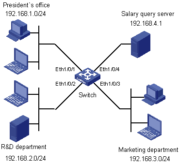
Figure 2-1 Network diagram for IPv4 ACL configuration
2.8.3 Configuration Procedure
1) Create a time range for office hours
# Create a periodic time range spanning 8:00 to 18:00 in working days.
<Switch> system-view
[Switch] time-range trname 8:00 to 18:00 working-day
2) Define an ACL to control access to the salary query server
# Configure a rule to control access of the R&D Department to the salary query server.
[Switch] acl number 3000
[Switch-acl-adv-3000] rule deny ip source 192.168.2.0 0.0.0.255 destination 192.168.4.1 0.0.0.0 time-range trname
[Switch-acl-adv-3000] quit
# Configure a rule to control access of the Marketing Department to the salary query server.
[Switch] acl number 3001
[Switch-acl-adv-3001] rule deny ip source 192.168.3.0 0.0.0.255 destination 192.168.4.1 0.0.0.0 time-range trname
[Switch-acl-adv-3001] quit
# Configure class c_rd for packets matching IPv4 ACL 3000.
[Switch] traffic classifier c_rd
[Switch-classifier-c_rd] if-match acl 3000
[Switch-classifier-c_rd] quit
# Configure traffic behavior b_rd to deny matching packets.
[Switch] traffic behavior b_rd
[Switch-behavior-b_rd] filter deny
[Switch-behavior-b_rd] quit
# Configure class c_market for packets matching IPv4 ACL 3001.
[Switch] traffic classifier c_market
[Switch-classifier-c_market] if-match acl 3001
[Switch-classifier-c_market] quit
# Configure traffic behavior b_ market to deny matching packets.
[Switch] traffic behavior b_market
[Switch-behavior-b_market] filter deny
[Switch-behavior-b_market] quit
# Configure QoS policy p_rd to use traffic behavior b_rd for class c_rd.
[Switch] qos policy p_rd
[Switch-qospolicy-p_rd] classifier c_rd behavior b_rd
[Switch-qospolicy-p_rd] quit
# Configure QoS policy p_market to use traffic behavior b_market for class c_market.
[Switch] qos policy p_market
[Switch-qospolicy-p_market] classifier c_market behavior b_market
[Switch-qospolicy-p_market] quit
# Apply QoS policy p_rd to interface Ethernet 1/0/2.
[Switch] interface Ethernet 1/0/2
[Switch-Ethernet1/0/2] qos apply policy p_rd inbound
[Switch-Ethernet1/0/2] quit
# Apply QoS policy p_market to interface Ethernet 1/0/3.
[Switch] interface Ethernet 1/0/3
[Switch-Ethernet1/0/3] qos apply policy p_market inbound
Chapter 3 IPv6 ACL Configuration
When configuring IPv6 ACLs, go to these sections for information you are interested in:
l Configuring a Basic IPv6 ACL
l Configuring an Advanced IPv6 ACL
l Displaying and Maintaining IPv6 ACLs
l IPv6 ACL Configuration Example
3.1 Creating a Time Range
Refer to section Creating a Time Range
3.2 Configuring a Basic IPv6 ACL
Basic IPv6 ACLs filter packets based on source IPv6 address. They are numbered in the range 2000 to 2999.
3.2.1 Configuration Prerequisites
If you want to reference a time range to a rule, define it with the time-range command first.
3.2.2 Configuration Procedure
Follow these steps to configure an IPv6 ACL:
|
To do… |
Use the command… |
|
|
Enter system view |
system-view |
–– |
|
Create and enter basic IPv6 ACL view |
acl ipv6 number acl6-number [ name acl6-name ] [ match-order { auto | config } ] |
Required The default match order is config. If you specify a name for an IPv6 ACL when creating the ACL, you can use the acl ipv6 name acl6-name command to enter the view of the ACL later. |
|
Create or modify a rule |
rule [ rule-id ] { deny | permit } [ fragment | logging | source { ipv6-address prefix-length | ipv6-address/prefix-length | any } | time-range time-name ] * |
Required To create multiple rules, repeat this step. |
|
Set a rule numbering step |
step step-value |
Optional The default step is 5. |
|
Create an IPv6 ACL description |
description text |
Optional By default, no IPv6 ACL description is present. |
|
Create a rule description |
rule rule-id comment text |
Optional By default, no rule description is present. |
Note that:
l You will fail to create or modify a rule if its permit/deny statement is exactly the same as another rule. In addition, if the ACL match order is set to auto rather than config, you cannot modify ACL rules.
l When defining ACL rules, you need not assign them IDs. The system can automatically assign rule IDs starting with 0 and increasing in certain rule numbering steps. A rule ID thus assigned is greater than the current highest rule ID. For example, if the rule numbering step is five and the current highest rule ID is 28, the next rule will be numbered 30. For detailed information about step, refer to the step command.
l You may use the display acl command to verify rules configured in an ACL. If the match order for this ACL is auto, rules are displayed in the depth-first match order rather than by rule number.
![]() Caution:
Caution:
l You can modify the match order of an IPv6 ACL with the acl ipv6 number acl6-number [ name acl6-name ] match-order { auto | config } command but only when it does not contain any rules.
l The rule specified in the rule comment command must have existed.
3.2.3 Configuration Examples
# Create IPv6 ACL 2000 to permit IPv6 packets with source address 2030:5060::9050/64 to pass while denying IPv6 packets with source address fe80:5060::8050/96.
<Sysname> system-view
[Sysname] acl ipv6 number 2000
[Sysname-acl6-basic-2000] rule permit source 2030:5060::9050/64
[Sysname-acl6-basic-2000] rule deny source fe80:5060::8050/96
# Verify the configuration.
[Sysname-acl6-basic-2000] display acl ipv6 2000
Basic IPv6 ACL 2000, named -none-, 2 rules,
ACL's step is 5
rule 0 permit source 2030:5060::9050/64
rule 5 deny source FE80:5060::8050/96
3.3 Configuring an Advanced IPv6 ACL
Advanced ACLs filter packets based on the source IPv6 address, destination IPv6 address, protocol carried on IPv6, and other protocol header fields such as the TCP/UDP source port, TCP/UDP destination port, ICMP message type, and ICMP message code.
Advanced IPv6 ACLs are numbered in the range 3000 to 3999. Compared with basic IPv6 ACLs, they allow of more flexible and accurate filtering.
3.3.1 Configuration Prerequisites
If you want to reference a time range to a rule, define it with the time-range command first.
3.3.2 Configuration Procedure
Follow these steps to configure an advanced IPv6 ACL:
|
To do… |
Use the command… |
Remarks |
|
Enter system view |
system-view |
–– |
|
Create and enter advanced IPv6 ACL view |
acl ipv6 number acl6-number [ name acl6-name ] [ match-order { auto | config } ] |
Required The default match order is config. If you specify a name for an IPv6 ACL when creating the ACL, you can use the acl ipv6 name acl6-name command to enter the view of the ACL later. |
|
Create or modify a rule |
rule [ rule-id ] { deny | permit } protocol [ destination { dest dest-prefix | dest/dest-prefix | any } | destination-port operator port1 [ port2 ] | dscp dscp | fragment | icmpv6-type { icmpv6-type icmpv6-code | icmpv6-message } | logging | source { source source-prefix | source/source-prefix | any } | source-port operator port1 [ port2 ] | time-range time-name ] * |
Required To create multiple rules, repeat this step. |
|
Set a rule numbering step |
step step-value |
Optional The default step is 5. |
|
Create an ACL description |
description text |
Optional By default, no IPv6 ACL description is present. |
|
Create a rule description |
rule rule-id comment text |
Optional By default, no rule description is present. |
Note that:
l You will fail to create or modify a rule if its permit/deny statement is exactly the same as another rule. In addition, if the ACL match order is set to auto rather than config, you cannot modify ACL rules.
l When defining ACL rules, you need not assign them IDs. The system can automatically assign rule IDs starting with 0 and increasing in certain rule numbering steps. A rule ID thus assigned is greater than the current highest rule ID. For example, if the rule numbering step is five and the current highest rule ID is 28, the next rule will be numbered 30. For detailed information about step, refer to the step command.
l You may use the display acl command to verify rules configured in an ACL. If the match order for this ACL is auto, rules are displayed in the depth-first match order rather than by rule number.
![]() Caution:
Caution:
l You can modify the match order of an IPv6 ACL with the acl ipv6 number acl6-number [ name acl6-name ] match-order { auto | config } command but only when it does not contain any rules.
l The rule specified in the rule comment command must have existed.
3.3.3 Configuration Examples
# Create IPv6 ACL 3000 to permit the TCP packets with the source address 2030:5060::9050/64 to pass.
<Sysname> system-view
[Sysname] acl ipv6 number 3000
[Sysname-acl6-adv-3000] rule permit tcp source 2030:5060::9050/64
# Verify the configuration.
[Sysname-acl6-adv-3000] display acl ipv6 3000
Advanced IPv6 ACL 3000, named -none-, 1 rule,
ACL's step is 5
rule 0 permit tcp source 2030:5060::9050/64
3.4 Copying an IPv6 ACL
This feature allows you to copy an existent IPv6 ACL to generate a new one, which is of the same type and has the same match order, match rules, rule numbering step and descriptions as the source IPv6 ACL.
3.4.1 Configuration Prerequisites
Make sure that the source IPv4 ACL exists while the destination IPv4 ACL does not.
3.4.2 Configuration Procedure
Follow these steps to copy an IPv6 ACL:
|
To do… |
Use the command… |
Remarks |
|
Enter system view |
system-view |
— |
|
Copy an existing IPv6 ACL to generate a new one of the same type |
acl ipv6 copy { source-acl6-number | name source-acl6-name } to { dest-acl6-number | name dest-acl6-name } |
Required |
![]() Caution:
Caution:
l The source IPv6 ACL and the destination IPv6 ACL must be of the same type.
l The generated ACL does not take the name of the source IPv6 ACL.
3.5 Displaying and Maintaining IPv6 ACLs
|
To do… |
Use the command… |
Remarks |
|
Display information about a specified or all IPv6 ACLs |
display acl ipv6 { acl6-number | all | name acl6-name } |
Available in any view |
|
Display the configuration and status on time range |
display time-range { time-name | all } |
Available in any view |
|
Clear statistics about a specified or all IPv6 ACLs that are referenced by upper layer software |
reset acl ipv6 counter { acl6-number | all | name acl6-name } |
Available in user view |
3.6 IPv6 ACL Configuration Example
3.6.1 Network Requirements
As shown in Figure 3-1, a company interconnects its departments through the switch.
Configure an ACL to deny access of the R&D department to external networks.
3.6.2 Network Diagram
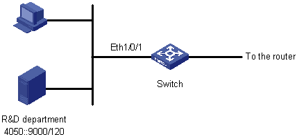
Figure 3-1 Network diagram for IPv6 ACL configuration
3.6.3 Configuration Procedure
# Create an IPv6 ACL 2000.
<Switch> system-view
[Switch] acl ipv6 number 2000
[Switch-acl6-basic-2000] rule deny source 4050::9000/120
[Switch-acl6-basic-2000] quit
# Configure class c_rd for packets matching IPv6 ACL 2000.
[Switch] traffic classifier c_rd
[Switch-classifier-c_rd] if-match acl ipv6 2000
[Switch-classifier-c_rd] quit
# Configure traffic behavior b_rd to deny matching packets.
[Switch] traffic behavior b_rd
[Switch-behavior-b_rd] filter deny
[Switch-behavior-b_rd] quit
# Configure QoS policy p_rd to use traffic behavior b_rd for class c_rd.
[Switch] qos policy p_rd
[Switch-qospolicy-p_rd] classifier c_rd behavior b_rd
[Switch-qospolicy-p_rd] quit
# Apply QoS policy p_rd to interface Ethernet 2/0/1.
[Switch] interface Ethernet 2/0/1
[Switch-Ethernet2/0/1] qos apply policy p_rd inbound
Chapter 4 Flow Template Configuration
4.1 Flow Template Overview
Flow templates are mainly used to limit the information included in the ACL rules. For an ACL rule to be successfully applied on a port, the information in the rule must be a subset of the information defined in the flow template applied on the port. For example, the flow template applied on a port defines source IP address, destination IP address, source TCP port, and destination TCP port. Then only the ACL rules that contain no other information items than the above ones can be applied correctly on the port for packet filtering, QoS and other purposes.
The switch supports both default flow template and user-defined flow templates. And, the user-defined flow templates can be classified into two types: basic and extended. Initially, if you do not reference any flow template on a port, the default one is used.
A flow template is configured globally and applied on a port.
![]() Caution:
Caution:
The use of flow templates is restricted to hardware-based ACL.
4.2 Configuring a Flow Template
Follow these steps to create a flow template and apply it to an interface:
|
To do… |
Use the command… |
Remarks |
|
|
Enter system view |
system-view |
–– |
|
|
Create a flow template |
Create a basic flow template |
flow-template flow-template-name basic { customer-cos | customer-vlan-id | dip | dipv6 | dmac | dport | dscp | ethernet-protocol | fragments | icmp-code | icmp-type | icmpv6-code | icmpv6-type | ip-precdence | ip-protocol | ipv6-dscp | ipv6-fragment | ipv6-protocol | service-cos | service-vlan-id | sip | sipv6 | smac | sport | tcp-flag | tos }* |
Optional Use either command. |
|
Create an extended flow template |
flow-template flow-template-name extend { [ start ] offset-max-value length-max-value | ipv4 offset-max-value length-max-value | ipv6 offset-max-value length-max-value | l2 offset-max-value length-max-value | l4 offset-max-value length-max-value }* |
||
|
Enter interface view or port group view |
Enter interface view |
interface interface-type interface-number |
Required |
|
Enter port group view |
port-group { aggregation agg-id | manual port-group-name } |
||
|
Apply the flow template to the interface or port group |
flow-template flow-template-name |
Optional The default one applies by default. |
|
& Note:
l The user-defined ACLs are used in conjunction with the extended user-defined flow template. When a port applies the extended flow template, you cannot apply policies including the basic and advanced ACLs on the port.
l The offset range of a user-defined extended flow template must cover the offset range of the cooperating user-defined ACL; otherwise, the user-defined ACL cannot be applied successfully.
l Before applying a user-defined template on a port, make sure the user-defined template is already configured. A port can be configured with only one flow template.
l Before you can apply a flow template on a port, make sure the following functions are disabled on the port: 802.1x, cluster (NDP, NTDP, HABP, and Cluster), DHCP Snooping, port isolation, MAC+IP+port binding, selective QinQ, and voice VLAN. And also, you are not recommended to use these functions after you apply a flow template on the port.
The S3610 and S5510 Series Ethernet Switches support up to two user-defined flow templates each. Note that the total length of all the elements in a basic flow template must be less than 16 bytes; otherwise, you will see an error message when applying the flow template. Table 4-1 lists the lengths of all elements.
Table 4-1 Lengths of various elements
|
Element |
Description |
Length (in bytes) |
|
customer-cos |
Customer 802.1p COS field |
1 |
|
customer-vlan-id |
Customer VLAN ID field |
6 |
|
dip |
Destination IP address field in IP head |
0 |
|
dipv6 |
Destination IPv6 address field in IPv6 head |
10 |
|
dmac |
Destination MAC address field in ethernet packet head |
6 |
|
dport |
Destination port field |
2 |
|
ethernet-protocol |
The protocol type field in ethernet packet head |
4 |
|
dscp |
DSCP field in IP head |
1 |
|
ip-precedence |
Precedence field in IP head |
|
|
tos |
ToS field in IP head |
|
|
fragments |
Fragments field in IP head |
0 |
|
icmp-code |
ICMP code field |
2 |
|
icmp-type |
ICMP type field |
2 |
|
icmpv6-code |
ICMPv6 code field |
2 |
|
icmpv6-type |
ICMPv6 type field |
2 |
|
ip-protocol |
The protocol type field in IP packet head |
0 |
|
ipv6-dscp |
DSCP field in IPv6 head |
1 |
|
ipv6-fragment |
Fragment field in IPv6 head |
0 |
|
ipv6-protocol |
The protocol type field in IPv6 packet head |
0 |
|
service-cos |
Service 802.1p COS field |
0 |
|
service-vlan-id |
Service VLAN ID field |
0 |
|
sip |
Source IP address field in IP head |
0 |
|
sipv6 |
Source IPv6 address field in IPv6 head |
0 |
|
smac |
Source MAC address field in ethernet packet head |
6 |
|
sport |
Source port field |
2 |
|
tcp-flag |
The flag field in tcp head |
1 |
& Note:
l Elements dscp, ip-precedence, and tos always use the same byte in a flow template, even if you configure all of them or any two of them.
l Similarly, icmp-code and icmp-type, when configured simultaneously, use two bytes. The same is true for icmpv6-code and icmpv6-type, icmp-code and sport, icmp-type and sport, icmpv6-code and sport, and icmpv6-type and sport.
4.3 Displaying Flow Templates
|
To do… |
Use the command… |
Remarks |
|
Display the configuration information of a specified or all user-defined flow templates |
display flow-template user-defined [ flow-template-name ] |
Available in any view |
|
Display information about the flow templates referenced to interfaces. |
display flow-template interface [ interface-type interface-number ] |
Available in any view |
4.4 Flow Template Configuration Example
I. Network requirements
Create flow templates and apply them to interfaces.
II. Configuration procedure
# Create basic flow template aaa.
<Sysname> system-view
[Sysname] flow-template aaa basic customer-cos smac customer-vlan-id
# Reference flow template aaa on interface Ethernet 1/0/1.
[Sysname] interface Ethernet 1/0/1
[Sysname-Ethernet1/0/1] flow-template aaa
[Sysname-Ethernet1/0/1] quit
# Create user-defined ACL 5000, and configure the extended flow template bbb to match ARP packets.
[Sysname] acl number 5000
[Sysname-acl-user-5000] rule deny l2 0806 ffff 12
[Sysname] flow-template bbb extend l2 12 2
# Reference flow template bbb on interface Ethernet 1/0/2.
[Sysname] interface Ethernet 1/0/2
[Sysname-Ethernet1/0/2] flow-template bbb
[Sysname-Ethernet1/0/2] quit
# Display information about all user-defined flow templates.
[Sysname] display flow-template user-defined
user-defined flow template: extend
name:bbb, index:1, total reference counts:0
fields: l2 12 2
user-defined flow template: basic
name:aaa, index:2, total reference counts:0
fields: smac customer-vlan-id customer-cos
# Display information about the user-defined flow templates referenced to interfaces.
[Sysname] display flow-template interface
Interface: Ethernet1/0/1
user-defined flow template: basic
name:aaa, index:1, total reference counts:1
fields: smac customer-vlan-id customer-cos
Interface: Ethernet1/0/2
user-defined flow template: extend
name:bbb, index:2, total reference counts:1
fields: l2 12 2
# Delete flow template aaa. As it is being referenced by interface Ethernet 1/0/1, remove it from the interface first.
[Sysname] interface Ethernet 1/0/1
[Sysname-Ethernet1/0/1] undo flow-template
[Sysname-Ethernet1/0/1] quit
[Sysname] undo flow-template name aaa