- Table of Contents
-
- H3C S3610[S5510] Series Ethernet Switches Operation Manual-Release 5301-(V1.03)
- 00-1Cover
- 00-2Product Overview
- 01-Login Configuration
- 02-VLAN Configuration
- 03-IP Addressing and Performance Configuration
- 04-QinQ-BPDU Tunneling Configuration
- 05-Port Correlation Configuration
- 06-Link Aggregation Configuration
- 07-MAC Address Table Management Configuration
- 08-IP Source Guard Configuration
- 09-MSTP Configuration
- 10-IPv6 Configuration
- 11-Routing Overview
- 12-IPv4 Routing Configuration
- 13-BFD-GR Configuration
- 14-IPv6 Routing Configuration
- 15-Multicast Protocol Configuration
- 16-802.1x-HABP-MAC Authentication Configuration
- 17-AAA-RADIUS-HWTACACS Configuration
- 18-ARP Configuration
- 19-DHCP Configuration
- 20-ACL Configuration
- 21-QoS Configuration
- 22-Port Mirroring Configuration
- 23-Cluster Management Configuration
- 24-UDP Helper Configuration
- 25-SNMP-RMON Configuration
- 26-NTP Configuration
- 27-DNS Configuration
- 28-File System Management Configuration
- 29-Information Center Configuration
- 30-System Maintaining and Debugging Configuration
- 31-NQA Configuration
- 32-VRRP Configuration
- 33-SSH Configuration
- 34-MCE Configuration
- 35-OAM Configuration
- 36-DLDP Configuration
- 37-RRPP Configuration
- 38-SSL-HTTPS Configuration
- 39-PKI Configuration
- 40-Appendix
- Related Documents
-
| Title | Size | Download |
|---|---|---|
| 35-OAM Configuration | 97 KB |
Table of Contents
1.1.2 OAM Connection Establishment
1.2.1 OAM Configuration Task List
1.2.2 Configuring Basic OAM Basic Functions
1.2.3 Configuring the Periods and Thresholds for OAM Link Error Event Detection
1.2.4 Enabling OAM Loopback Testing
1.3 Displaying and Maintaining OAM Configuration
Chapter 1 OAM Configuration
When performing OAM configuration, go to these sections for information you are interested in:
l Displaying and Maintaining OAM Configuration
1.1 OAM Overview
Ethernet OAM (meaning operation, administration, and maintenance) is a tool for monitoring network. It operates on data link layer and can report information about networks to network administrators through the OAMPDUs exchanged between devices, enabling network administrators to manage the network more effectively.
Currently, Ethernet OAM is mainly used for detecting data link layer problems occurred in the “last mile”. By enabling Ethernet OAM on two devices connected by a point-to-point connection, you can monitor the link status of the link between the two devices. Ethernet OAM provides the following functions.
l Link performance monitoring, for detecting link errors
l Fault detection and alarm, for reporting link errors to the administrators
l Loopback testing, for detecting link errors through non-OAMPDUs
1.1.1 Types of OAMPDUs
Figure 1-1 shows the format of different types of OAMPDU.
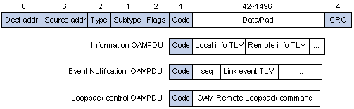
Figure 1-1 The format of different types of OAMPDU
The fields in an OAMPDU are described as follows.
l The Dest addr field holds the destination MAC address of an OAMPDU, which is the multicast MAC address 0180c2000002.
l The Source addr field holds the source MAC address of an OAMPDU, which is the bridge MAC address of the sending side.
l The Type field indicates the protocol type of an OAMPDU, which is fixed to 0x8809.
l The Subtype field holds the protocol sub-type of an OAMPDU, which is fixed to 0x03.
l The Flags field contains the information about an OAM entity.
l The Code field indicates the type of an OAMPDU. The value of this field can be 0x00, 0x01, and 0x04, which identifies Information OAMPDU, Event notification OAMPDU, and Loopback control OAMPDU.
As mentioned above, Information OAMPDU, Event Notification OAMPDU, and Loopback control OAMPDU are commonly used, which are described as follows.
l Information OAMPDUs are used for passing the state information about an Ethernet OAM entity (including the information about the local device and remote devices, and customized information) to another Ethernet OAM entity and maintain OAM connections.
l Event notification OAMPDUs are used for link monitoring. They are sent as an alarm in case a failure occurs to the link connecting the local OAM entity and a remote OAM entity.
l Loopback control OAMPDUs are used for remote loopback control. By inserting the information used to enable/disable loopback to a Loopback control OAMPDU, you can enable/disable loopback on a remote OAM entity.
1.1.2 OAM Connection Establishment
Following are the four OAM functions.
l OAM connection establishment
l Link monitoring
l Remote fault detection
l Remote loopback testing
Note that OAM connection is the base of all the other Ethernet OAM functions.
I. OAM connection establishment
OAM connection establishment is also known as the Discovery phase, where an OAM entity discovers other OAM entities and sessions between OAM entities are established.
In this phase, interconnected OAM entities notify the peer of their OAM configuration information and the OAM capabilities of the local nodes to support OAM by exchanging Information OAMPDUs and determine whether OAM connections can be established. An OAM connection can be established only when the settings concerning Loopback, link detecting, and link event of the both side match. After an OAM connection is established, OAM takes effect on it.
As for OAM connection establishment, a device can operate in two modes: active OAM mode and passive OAM mode. Only devices operating in active OAM mode can initiate OAM connection establishment processes. Those operating in passive OAM mode, however, wait and respond to OAM connection establishment requests and take corresponding operations. Table 1-1 compares active OAM mode with passive OAM mode.
Table 1-1 Active OAM mode and passive OAM mode
|
Item |
Active OAM mode |
Passive OAM mode |
|
Initiating OAM Discovery |
Available |
Unavailable |
|
Responding to OAM Discovery |
Available |
Available |
|
Transmitting Information OAMPDUs |
Available |
Available |
|
Transmitting Event Notification OAMPDUs |
Available |
Available |
|
Transmitting Information OAMPDUs with the Data/Pad field being empty |
Available |
Available |
|
Transmitting Loopback Control OAMPDUs |
Available |
Unavailable |
|
Responding to Loopback Control OAMPDUs |
Available (if both sides operate in active OAM mode) |
Available |
|
Transmitting organization-specific OAMPDUs |
Available |
Available |
After an OAM connection is established, the OAM entities on both sides exchange Information OAMPDUs periodically to keep the OAM connection valid. If an OAM entity receives no Information OAMPDU for five seconds, the OAM connection is considered invalid. In this case, to enable the OAM entities to communicate with each other again, a new OAM connection is required.
The interval to send Information OAMPDUs is determined by a timer. Up to ten Information OAMPDUs can be sent in a second.
II. Link Monitoring
Link monitoring is used to detect and locate link faults in various environments. In OAM, link faults are categorized into link events.
OAM implements link monitoring through the exchange of Event Notification OAMPDUs. Upon detecting a link fault, the local device sends an Event Notification OAMPDU to the remote OAM entity to report the fault event. Link monitoring enables network administrators to be informed of network status in time. Table 1-2 describes the link events.
Table 1-2 OAM link error events
|
OAM link events |
Description |
|
Error signal event |
A signal error event occurs if the number of signal errors in specific period exceeds the threshold. |
|
Error frame event |
A Frame error event occurs if the number of frame errors in specific period exceeds the threshold. |
|
Frame-percentage error event |
A frame-percentage error event occurs if the number of frame errors in specific number of received frames exceeds the threshold |
|
Second-percentage error event |
A second-percentage error second event occurs if the number of error seconds in specific period (measured in seconds) exceeds the threshold. A second is called an error second if error frames occur in the second. |
III. Remote Fault Detection
Error detection in an Ethernet is difficult, especially when the physical connection in the network is not interrupted but network performance degrades gradually. The flag field defined in OAMPDUs allows an OAM entity to send error information to its peer. It can identify the following link faults.
l Link Fault: Peer link signal is lost.
l Dying Gasp: An unexpected fault, such as power failure, occurred.
l Critical Event: An undetermined critical event happened.
As Information OAMPDUs are sent periodically across OAM connections, an OAM entity can inform one of its OAM peers of link faults through Information OAMPADUs to enable the network administrator to get informed of link status and troubleshoot in time.
IV. Remote loopback testing
Remote loopback testing is available only after the OAM connection is established. With remote loopback enabled, the OAM entity operating in active OAM mode issues remote loopback requests and the peer responds to them. If the peer operates in the loopback mode, it returns all the PDUs except OAMPDUs to the senders along the original paths.
Performing remote loopback testing periodically helps to detecting network faults in time. Furthermore, performing remote loopback testing by network segments helps to locate network faults.
1.1.3 Standards and Protocols
OAM is defined in IEEE 802.3h.
1.2 OAM Configuration
1.2.1 OAM Configuration Task List
Complete the following tasks to configure OAM:
|
Task |
Remarks |
|
Required |
|
|
Configuring the Periods and Thresholds for OAM Link Error Event Detection |
Optional |
|
Optional |
1.2.2 Configuring Basic OAM Basic Functions
Follow these steps to configure basic OAM functions:
|
To do… |
Use the command… |
Remarks |
|
Enter system view |
system-view |
— |
|
Enter Ethernet port view |
interface interface-type interface-number |
— |
|
Set OAM operating mode |
oam mode { active | passive } |
Optional The default is active OAM mode. |
|
Enable OAM on the current port |
oam enable |
Required OAM is disabled by default. After OAM is enabled, the OAM entity tries to establish OAM connection with its peer. |
& Note:
l OAM connections can be initiated only by OAM entities operating in active OAM mode, while those operating in passive mode wait and respond to the connection requests sent by their peers.
l No OAM connection can be established between two OAM entities operating in passive OAM mode.
l With OAM enabled, you cannot change the OAM operating mode. To do so, you need to disable OAM first.
1.2.3 Configuring the Periods and Thresholds for OAM Link Error Event Detection
Follow these steps to configure the periods and thresholds for OAM link error event detection:
|
To do… |
Use the command… |
Remarks |
|
Enter system view |
system-view |
— |
|
Configure the period for error signal event detection |
oam errored-symbol period period-value |
Optional The default is one second. |
|
Configure the threshold for error signal event detection |
oam errored-symbol threshold threshold-value |
Optional The default is 1. |
|
Configure the period for error frame event detection |
oam errored-frame period period-value |
Optional The default is one second. |
|
Configure the threshold for error frame event detection |
oam errored-frame threshold threshold-value |
Optional The default is 1. |
|
Configure the period for frame-percentage error event detection |
oam errored-frame-period period period-value |
Optional The default is 1,000 milliseconds. |
|
Configure the threshold for frame-percentage error event detection |
oam errored-frame-period threshold threshold-value |
Optional The default is 1. |
|
Configure the period for second-percentage error event detection |
oam errored-frame-seconds period period-value |
Optional The default is 60 seconds. |
|
Configure the threshold for second-percentage error event detection |
oam errored-frame-seconds threshold threshold-value |
Optional The default is 1. Make sure the threshold for second-percentage error event detection is less than the period for second-percentage error event detection for second-percentage error events to be detected. |
& Note:
l An error signal event occurs when a period for error signal event detection expires and the number of the signal errors occurred on an Ethernet port is larger than or (equal to) the threshold for error signal event detection.
l An error frame event occurs when a period for error frame event detection expires and the number of the frame errors occurred on an Ethernet port is larger than (or equal to) the threshold for error frame event detection.
l A frame-percentage error event occurs when a period for frame-percentage error event detection expires and the number of the frame errors occurred on an Ethernet port is larger than (or equal to) the threshold for frame-percentage error event detection.
l As for frame-percentage error event detection, the system first uses the following expression to convert the period for frame-percentage error event detection to the maximum number of 64-byte frames that can be transmitted through an Ethernet port in the period: bandwidth * period / (64 * 8 * 1000), where “bandwidth” is the port bandwidth (in bps) and “period” is the configured period (in milliseconds).
l A second-percentage error event occurs when a period for second-percentage error event detection expires and the number of the error seconds of an Ethernet port is larger than (or equal to) the threshold for second-percentage error event detection. (A second is called an error second if error frames occur in the second.)
l The periods and the thresholds configured apply to all the Ethernet ports on which OAM connections are established.
1.2.4 Enabling OAM Loopback Testing
Follow these steps to enable OAM loopback testing:
|
To do… |
Use the command… |
Remarks |
|
Enter system view |
system-view |
— |
|
Enter Ethernet port view |
interface interface-type interface-number |
— |
|
Enable OAM loopback testing |
oam loopback |
Required Disabled by default. |
& Note:
l Currently, OAM external loopback is only available on 1000 Mbps Ethernet ports (SFP ports with electrical ports installed not included) operating at a speed of 1000 Mbps, 100 Mbps, or 10 Mbps.
l OAM loopback testing is available only after the OAM connection is established.
l OAM loopback testing can be performed by OAM entities operating in the active OAM mode only.
l OAM loopback testing needs the support of the peer hardware.
l OAM loopback testing is only applicable to individual links. It is not applicable to aggregation links. So when performing OAM loopback testing, make sure none of the ports involved belongs to an aggregation group.
l Enabling OAM loopback testing results in all the data communications being stopped. After OAM loopback testing is disabled, all the ports involved will be shut down and then brought up.
l OAM loopback testing is disabled when you execute the undo oam enable command to disable OAM; when you execute the undo oam loopback command to disable OAM loopback testing; or when the OAM connection is timed out.
1.3 Displaying and Maintaining OAM Configuration
|
To do… |
Use the command… |
Remarks |
|
Display global OAM configuration |
display oam configuration |
Available in any view |
|
Display the statistics on critical events after an OAM connection is established |
display oam critical-event [ interface interface-type interface-number ] |
|
|
Display the statistics on OAM link error events after an OAM connection is established or after you clear the statistics |
display oam link-event { local | remote } [ interface interface-type interface-number ] |
|
|
Display the information about an OAM connection |
display oam { local | remote } [ interface interface-type interface-number ] |
|
|
Clear statistics on OAM packets and OAM link error events |
reset oam [ interface interface-type interface-number ] |
Available in user view only |
1.4 OAM Configuration Example
I. Network requirements
l Enable OAM on Device A and Device B to manage links on data link layer.
l Monitor link performance and collect statistics about the error frames received by Device A.
II. Network diagram
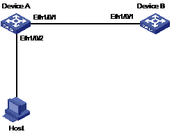
Figure 1-2 Network diagram for OAM configuration
III. Configuration procedure
1) Configure Device A:
# Configure Ethernet 1/0/1 to operate in passive OAM mode and enable OAM for it.
<DeviceA> system-view
[DeviceA] interface ethernet 1/0/1
[DeviceA-Ethernet1/0/1] oam mode passive
[DeviceA-Ethernet1/0/1] oam enable
[DeviceA-Ethernet1/0/1] quit
# Set the period for error frame event detection to 20 seconds.
[DeviceA] oam errored-frame period 20
# Set the threshold for error frame event detection to 10.
[DeviceA] oam errored-frame threshold 10
# Display global OAM configuration.
[DeviceA] display oam configuration
Configuration of the errored symbol/frame event window/threshold :
--------------------------------------------------------
Errored-symbol Event period : 1
Errored-symbol Event threshold : 1
Errored-frame Event period : 20
Errored-frame Event threshold : 10
Errored-frame-period Event period : 1000
Errored-frame-period Event threshold : 1
Errored-frame-seconds Event period : 60
Errored-frame-seconds Event threshold : 1
2) Configure Device B:
# Configure Ethernet 1/0/1 to operate in active OAM mode (the default OAM mode) and enable OAM for it.
<DeviceB> system-view
[DeviceB] interface ethernet 1/0/1
[DeviceB-Ethernet1/0/1] oam enable
[DeviceB-Ethernet1/0/1] quit
# Display OAM link error event statistics.
[DeviceB] display oam link-event remote
Port :Ethernet1/0/1
Link Status :Up
OAMRemoteErrFrameEvent : (ms = milliseconds)
---------------------------------------------------------------------
Event Time Stamp : 5789 Errored FrameWindow : 10(100ms)
Errored Frame Threshold : 1 Errored Frame : 3
Error Running Total : 35 Event Running Total : 17
The above information indicates that 35 errors occurred since OAM is enabled on Device A, 17 of which are caused by error frames. The link is instable.