- Table of Contents
-
- H3C S3610[S5510] Series Ethernet Switches Operation Manual-Release 5301-(V1.03)
- 00-1Cover
- 00-2Product Overview
- 01-Login Configuration
- 02-VLAN Configuration
- 03-IP Addressing and Performance Configuration
- 04-QinQ-BPDU Tunneling Configuration
- 05-Port Correlation Configuration
- 06-Link Aggregation Configuration
- 07-MAC Address Table Management Configuration
- 08-IP Source Guard Configuration
- 09-MSTP Configuration
- 10-IPv6 Configuration
- 11-Routing Overview
- 12-IPv4 Routing Configuration
- 13-BFD-GR Configuration
- 14-IPv6 Routing Configuration
- 15-Multicast Protocol Configuration
- 16-802.1x-HABP-MAC Authentication Configuration
- 17-AAA-RADIUS-HWTACACS Configuration
- 18-ARP Configuration
- 19-DHCP Configuration
- 20-ACL Configuration
- 21-QoS Configuration
- 22-Port Mirroring Configuration
- 23-Cluster Management Configuration
- 24-UDP Helper Configuration
- 25-SNMP-RMON Configuration
- 26-NTP Configuration
- 27-DNS Configuration
- 28-File System Management Configuration
- 29-Information Center Configuration
- 30-System Maintaining and Debugging Configuration
- 31-NQA Configuration
- 32-VRRP Configuration
- 33-SSH Configuration
- 34-MCE Configuration
- 35-OAM Configuration
- 36-DLDP Configuration
- 37-RRPP Configuration
- 38-SSL-HTTPS Configuration
- 39-PKI Configuration
- 40-Appendix
- Related Documents
-
| Title | Size | Download |
|---|---|---|
| 12-IPv4 Routing Configuration | 2 MB |
Table of Contents
Chapter 1 Static Routing Configuration
1.1.3 Application Environment of Static Routing
1.2 Configuring a Static Route
1.2.1 Configuration Prerequisites
1.3 Displaying and Maintaining Static Routes
2.2 Configuring RIP Basic Functions
2.2.1 Configuration Prerequisites
2.3 Configuring RIP Route Control
2.3.1 Configuring an Additional Routing Metric
2.3.2 Configuring RIPv2 Route Summarization
2.3.3 Disabling Host Route Reception
2.3.4 Advertising a Default Route
2.3.5 Configuring Inbound/Outbound Route Filtering
2.3.6 Configuring a Priority for RIP
2.3.7 Configuring RIP Route Redistribution
2.4 Configuring RIP Network Optimization
2.4.2 Configuring Split Horizon and Poison Reverse
2.4.3 Configuring the Maximum Number of Load Balanced Routes
2.4.4 Enabling Zero Field Check on Incoming RIPv1 Messages
2.4.5 Enabling Source IP Address Check on Incoming RIP Updates
2.4.6 Configuring RIPv2 Message Authentication
2.4.7 Specifying a RIP Neighbor
2.4.8 Configuring RIP-to-MIB Binding
2.5 Displaying and Maintaining RIP
2.6 RIP Configuration Examples
2.6.2 Configuring RIP Route Redistribution
2.7.2 Route Oscillation Occurred
3.1.2 OSPF Area Partition and Route Summarization
3.1.3 Classification of OSPF Networks
3.2 OSPF Configuration Task List
3.3 Configuring OSPF Basic Functions
3.4 Configuring OSPF Area Parameters
3.5 Configuring OSPF Network Types
3.5.2 Configuring the OSPF Network Type for an Interface
3.5.3 Configuring an NBMA Neighbor
3.5.4 Configuring a Router Priority for an OSPF Interface
3.6 Configuring OSPF Route Control
3.6.2 Configuring OSPF Route Summarization
3.6.3 Configuring OSPF Inbound Route Filtering
3.6.4 Configuring ABR Type-3 LSA Filtering
3.6.5 Configuring an OSPF Cost for an Interface
3.6.6 Configuring the Maximum Number of OSPF Routes
3.6.7 Configuring the Maximum Number of Load-balanced Routes
3.6.8 Configuring a Priority for OSPF
3.6.9 Configuring OSPF Route Redistribution
3.7 Configuring OSPF Network Optimization
3.7.2 Configuring OSPF Packet Timers
3.7.3 Specifying an LSA Transmission Delay
3.7.4 Specifying SPF Calculation Interval
3.7.5 Specifying the LSA Minimum Repeat Arrival Interval
3.7.6 Specifying the LSA Generation Interval
3.7.7 Disabling Interfaces from Sending OSPF Packets
3.7.8 Configuring Stub Routers
3.7.9 Configuring OSPF Authentication
3.7.10 Adding the Interface MTU into DD Packets
3.7.11 Configuring the Maximum Number of External LSAs in LSDB
3.7.12 Making External Route Selection Rules Defined in RFC1583 Compatible
3.7.13 Logging Neighbor State Changes
3.7.14 Configuring OSPF Network Management
3.7.15 Enabling the Advertisement and Reception of Opaque LSAs
3.8 Configuring OSPF Graceful Restart
3.8.1 Configuring the OSPF GR Capability
3.8.2 Configuring the OSPF GR Helper
3.8.3 Triggering OSPF Graceful Restart
3.9 Displaying and Maintaining OSPF
3.10 OSPF Configuration Examples
3.10.1 Configuring OSPF Basic Functions
3.10.2 Configuring an OSPF Stub Area
3.10.3 Configuring an OSPF NSSA Area
3.10.4 Configuring OSPF DR Election
3.10.5 Configuring OSPF Virtual Links
3.10.6 OSPF Graceful Restart Configuration Example
3.11 Troubleshooting OSPF Configuration
3.11.1 No OSPF Neighbor Relationship Established
3.11.2 Incorrect Routing Information
4.1.5 IS-IS Features Supported
4.2 IS-IS Configuration Task List
4.3 Configuring IS-IS Basic Functions
4.3.1 Configuration Prerequisites
4.4 Configuring IS-IS Routing Information Control
4.4.1 Configuration Prerequisites
4.4.2 Specifying a Priority for IS-IS
4.4.3 Configuring IS-IS Link Cost
4.4.4 Configuring the Maximum Number of Equal Cost Routes
4.4.5 Configuring IS-IS Route Summarization
4.4.6 Advertising a Default Route
4.4.7 Configuring Inbound Route Filtering
4.4.8 Configuring Route Redistribution
4.4.9 Configuring IS-IS Route Leaking
4.5 Tuning and Optimizing IS-IS Network
4.5.1 Configuration Prerequisites
4.5.2 Configuring a DIS Priority for an Interface
4.5.3 Configuring IS-IS Timers
4.5.4 Disabling an Interface from Sending/Receiving IS-IS Hello Packets
4.5.5 Configuring LSP Parameters
4.5.6 Configuring SPF Parameters
4.5.7 Configuring Dynamic Host Name Mapping
4.5.8 Configuring IS-IS Authentication
4.5.9 Configuring LSDB Overload Tag
4.5.10 Logging the Adjacency Changes
4.5.11 Enabling an Interface to Send Small Hello Packets
4.7 Displaying and Maintaining IS-IS
4.8 IS-IS Configuration Example
4.8.1 IS-IS Basic Configuration
4.8.2 DIS Selection Configuration
4.8.3 IS-IS-based Graceful Restart Configuration Example
5.1.4 IBGP and IGP Synchronization
5.1.5 Settlements for Problems Caused by Large Scale BGP Networks
5.2 BGP Configuration Task List
5.3 Configuring BGP Basic Functions
5.4 Controlling Route Distribution and Reception
5.4.2 Configuring BGP Route Redistribution
5.4.3 Configuring BGP Route Summarization
5.4.4 Advertising a Default Route to a Peer or Peer Group
5.4.5 Configuring BGP Route Distribution Filtering Policies
5.4.6 Configuring BGP Route Reception Filtering Policies
5.4.7 Enabling BGP and IGP Route Synchronization
5.4.8 Configuring BGP Route Dampening
5.5 Configuring BGP Route Attributes
5.6 Tuning and Optimizing BGP Networks
5.7 Configuring a Large Scale BGP Network
5.7.1 Configuration Prerequisites
5.7.2 Configuring BGP Peer Groups
5.7.3 Configuring BGP Community
5.7.4 Configuring a BGP Route Reflector
5.7.5 Configuring a BGP Confederation
5.9 Displaying and Maintaining BGP
5.9.2 Resetting BGP Connections
5.9.3 Clearing BGP Information
5.10 BGP Configuration Examples
5.10.1 BGP Basic Configuration
5.10.2 BGP and IGP Synchronization Configuration
5.10.3 BGP Load Balancing and MED Attribute Configuration
5.10.4 BGP Community Configuration
5.10.5 BGP Route Reflector Configuration
5.10.6 BGP Confederation Configuration
5.10.7 BGP Path Selection Configuration
5.11.1 No BGP Peer Relationship Established
Chapter 6 Routing Policy Configuration
6.1 Introduction to Routing Policy
6.1.1 Routing Policy and Policy Routing
6.1.3 Routing Policy Application
6.2 Routing Policy Configuration Task List
6.3.2 Defining an IPv4 Prefix List
6.3.3 Defining an AS Path List
6.3.4 Defining a Community List
6.3.5 Defining an Extended Community List
6.4 Configuring a Routing Policy
6.4.2 Creating a Routing Policy
6.4.3 Defining if-match Clauses for the Routing Policy
6.4.4 Defining apply Clauses for the Routing Policy
6.5 Displaying and Maintaining the Routing Policy
6.6 Routing Policy Configuration Example
6.6.1 Applying Routing Policy When Redistributing IPv4 Routes
6.7 Troubleshooting Routing Policy Configuration
6.7.1 IPv4 Routing Information Filtering Failure
Chapter 1 Static Routing Configuration
When configuring a static route, go to these sections for information you are interested in:
l Displaying and Maintaining Static Routes
& Note:
The term “router” in this document refers to a router in a generic sense or a Layer 3 switch.
1.1 Introduction
1.1.1 Static Route
A static route is a special route that is manually configured by the network administrator. If a network’s topology is simple, you only need to configure static routes for the network to work normally. The proper configuration and usage of static routes can improve network performance and ensure bandwidth for important network applications.
The disadvantage of using static routes is that they cannot adapt to network topology changes. If a fault or a topological change occurs in the network, the routes will be unreachable and the network breaks. In this case, the network administrator has to modify the static routes manually.
1.1.2 Default Route
A router selects the default route only when it cannot find any matching entry in the routing table.
If there is no default route and the destination address of the packet fails to match any entry in the routing table, the packet will be discarded and an ICMP packet will be sent to the source to report that the destination or the network is unreachable.
You can create the default route with both destination and mask being 0.0.0.0, and some dynamic routing protocols, such as OSPF, RIP and IS-IS, can also generate the default route.
1.1.3 Application Environment of Static Routing
Before configuring a static route, you need to know the following concepts:
1) Destination address and mask
In the ip route-static command, an IPv4 address is in dotted decimal format and a mask can be either in dotted decimal format or in the form of mask length (the digits of consecutive 1s in the mask).
2) Output interface and next hop address
While configuring a static route, you can specify either the output interface or the next hop address depending on the specific occasion. The next hop address can not be a local interface IP address; otherwise, the route configuration will not take effect.
In fact, all the route entries must have a next hop address. When forwarding a packet, a router first searches the routing table for the route to the destination address of the packet. The system can find the corresponding link layer address and forward the packet only after the next hop address is specified.
When specifying the output interface, note that:
l If the output interface is a NULL 0 or loopback interface, there is no need to configure the next hop address.
l You are not recommended to specify a broadcast interface (such as a VLAN interface) as the output interface, because a broadcast interface may have multiple next hops. If you have to do so, you must specify the corresponding next hop for the output interface.
3) Other attributes
You can configure different preferences for different static routes so that route management policies can be applied more flexibly. For example, specifying the same preference for different routes to the same destination enables load sharing, while specifying different preferences for these routes enables route backup.
You can also enable bidirectional forwarding detection (BFD) to implement fast detection on the next hops of static routes. When a next hop is unreachable, the system can switch to a backup route instantly.
1.2 Configuring a Static Route
1.2.1 Configuration Prerequisites
Before configuring a static route, you need to configure the IP addresses for related interfaces
1.2.2 Configuration Procedure
Follow these steps to configure a static route:
|
To do… |
Use the command… |
Remarks |
|
Enter system view |
system-view |
— |
|
Configure a static route |
ip route-static dest-address { mask | mask-length } { gateway-address [ bfd { control-packet | echo-packet } ] | interface-type interface-number [ gateway-address [ bfd { control-packet | echo-packet } ] ] | vpn-instance d-vpn-instance-name gateway-address [ bfd { control-packet | echo-packet } ] } [ preference preference-value ] [ tag tag-value ] [ description description-text ] |
Required By default, preference for static routes is 60, tag is 0, and no description information is configured. |
|
ip route-static vpn-instance s-vpn-instance-name&<1-6> dest-address { mask | mask-length } { gateway-address [ bfd { control-packet | echo-packet } ] [ public ] | interface-type interface-number [ gateway-address [ bfd { control-packet | echo-packet } ] ] | vpn-instance d-vpn-instance-name gateway-address [ bfd { control-packet | echo-packet } ] } [ preference preference-value ] [ tag tag-value ] [ description description-text ] |
||
|
Configure the default preference for static routes |
ip route-static default-preference default-preference-value |
Optional 60 by default |
& Note:
l When configuring a static route, the static route does not take effect if you specify the next hop address first and then configure it as the IP address of a local interface, such as a VLAN interface.
l If you do not specify the preference when configuring a static route, the default preference will be used. Reconfiguring the default preference applies only to newly created static routes.
l You can flexibly control static routes by configuring tag values and using the tag values in the routing policy.
l If the destination IP address and mask are both configured as 0.0.0.0 with the ip route-static command, the route is the default route.
l To implement BFD with the control-packet mode, the remote end must create a BFD session; otherwise the BFD function cannot work. To implement BFD with the echo-packet mode, the BFD function can work without the remote end needing to create any BFD session.
l If route oscillation occurs, enabling BFD may make the oscillation more severe. Be cautious for use of this kind.
1.3 Displaying and Maintaining Static Routes
|
To do… |
Use the command… |
Remarks |
|
Display the current configuration information |
display current-configuration |
Available in any view |
|
Display the brief information of the IP routing table |
display ip routing-table |
|
|
Display the detailed information of the IP routing table |
display ip routing-table verbose |
|
|
View information of static routes |
display ip routing-table protocol static [ inactive | verbose ] |
|
|
Delete all the static routes |
delete [ vpn-instance vpn-instance-name ] static-routes all |
Available In system view |
1.4 Configuration Example
I. Network requirements
The IP addresses and masks of the switches and hosts are shown in the following figure. Static routes are required for interconnection between any two hosts.
II. Network diagram
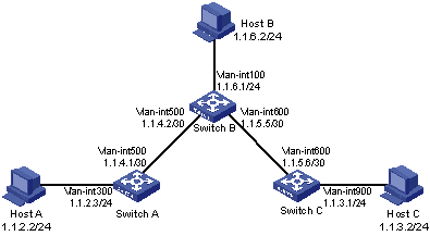
Figure 1-1 Network diagram for static route configuration
III. Configuration procedure
1) Configuring IP addresses for interfaces (omitted)
2) Configuring static routes
# Configure a default route on Switch A
<SwitchA> system-view
[SwitchA] ip route-static 0.0.0.0 0.0.0.0 1.1.4.2
# Configure two static routes on Switch B
<SwitchB> system-view
[SwitchB] ip route-static 1.1.2.0 255.255.255.0 1.1.4.1
[SwitchB] ip route-static 1.1.3.0 255.255.255.0 1.1.5.6
# Configure a default route on Switch C
<SwitchC> system-view
[SwitchC] ip route-static 0.0.0.0 0.0.0.0 1.1.5.5
3) Configure the hosts
The default gateways for the three hosts A, B and C are 1.1.2.3, 1.1.6.1 and 1.1.3.1 respectively. The configuration procedure is omitted.
4) Display the configuration result
# Display the IP routing table of Switch A.
[SwitchA] display ip routing-table
Routing Tables: Public
Destinations : 7 Routes : 7
Destination/Mask Proto Pre Cost NextHop Interface
0.0.0.0/0 Static 60 0 1.1.4.2 Vlan500
1.1.2.0/24 Direct 0 0 1.1.2.3 Vlan300
1.1.2.3/32 Direct 0 0 127.0.0.1 InLoop0
1.1.4.0/30 Direct 0 0 1.1.4.1 Vlan500
1.1.4.1/32 Direct 0 0 127.0.0.1 InLoop0
127.0.0.0/8 Direct 0 0 127.0.0.1 InLoop0
127.0.0.1/32 Direct 0 0 127.0.0.1 InLoop0
# Display the IP routing table of Switch B.
[SwitchB] display ip routing-table
Routing Tables: Public
Destinations : 10 Routes : 10
Destination/Mask Proto Pre Cost NextHop Interface
1.1.2.0/24 Static 60 0 1.1.4.1 Vlan500
1.1.3.0/24 Static 60 0 1.1.5.6 Vlan600
1.1.4.0/30 Direct 0 0 1.1.4.2 Vlan500
1.1.4.2/32 Direct 0 0 127.0.0.1 InLoop0
1.1.5.0/30 Direct 0 0 1.1.5.5 Vlan600
1.1.5.5/32 Direct 0 0 127.0.0.1 InLoop0
127.0.0.0/8 Direct 0 0 127.0.0.1 InLoop0
127.0.0.1/32 Direct 0 0 127.0.0.1 InLoop0
1.1.6.0/24 Direct 0 0 1.1.6.1 Vlan100
1.1.6.1/32 Direct 0 0 127.0.0.1 InLoop0
Chapter 2 RIP Configuration
& Note:
The term “router” in this document refers to a router in a generic sense or a Layer 3 switch.
When configuring RIP, go to these sections for information you are interested in:
l Configuring RIP Basic Functions
l Configuring RIP Route Control
l Configuring RIP Network Optimization
l Displaying and Maintaining RIP
2.1 RIP Overview
RIP is a simple Interior Gateway Protocol (IGP), mainly used in small-sized networks, such as academic networks and simple LANs. RIP is not applicable to complex networks.
RIP is still widely used in practical networking due to easier implementation, configuration and maintenance than OSPF and IS-IS.
2.1.1 RIP Working Mechanism
I. Basic concepts
RIP is a distance vector routing protocol, using UDP packets for exchanging information through port 520.
RIP uses a hop count to measure the distance to a destination. The hop count is known as the metric. The hop count from a router to a directly connected network is 0. The hop count from one router to a directly connected router is 1. To limit convergence time, the range of RIP metric value is from 0 to 15. A metric value of 16 (or bigger) is considered infinite, which means the destination network is unreachable. That is why RIP is not suitable for large-scaled networks.
RIP prevents routing loops by implementing the split horizon and poison reverse functions.
II. RIP routing table
A RIP router has a routing table containing routing entries of all reachable destinations, and each routing entry contains:
l Destination address: IP address of a host or a network.
l Next hop: IP address of the adjacent router’s interface to reach the destination.
l Egress interface: Packet outgoing interface.
l Metric: Cost from the local router to the destination.
l Route time: Time elapsed since the routing entry was last updated. The time is reset to 0 every time the routing entry is updated.
l Route tag: Identifies a route, used in a routing policy to flexibly control routes. For information about routing policy, refer to Routing Policy Configuration.
III. RIP timers
RIP employs four timers, update, timeout, suppress, and garbage-collect.
l The update timer defines the interval between routing updates.
l The timeout timer defines the route aging time. If no update for a route is received within the aging time, the metric of the route is set to 16 in the routing table.
l The suppress timer defines how long a RIP route stays in the suppressed state. When the metric of a route is 16, the route enters the suppressed state. In the suppressed state, only routes which come from the same neighbor and whose metric is less than 16 will be received by the router to replace unreachable routes.
l The garbage-collect timer defines the interval from when the metric of a route becomes 16 to when it is deleted from the routing table. During the garbage-collect timer length, RIP advertises the route with the routing metric set to 16. If no update is announced for that route after the garbage-collect timer expires, the route will be deleted from the routing table.
IV. Routing loops prevention
RIP is a distance vector (D-V) routing protocol. Since a RIP router advertises its own routing table to neighbors, routing loops may occur.
RIP uses the following mechanisms to prevent routing loops.
l Counting to infinity. The metric value of 16 is defined as unreachable. When a routing loop occurs, the metric value of the route will increment to 16.
l Split horizon. A router does not send the routing information learned from a neighbor to the neighbor to prevent routing loops and save bandwidth.
l Poison reverse. A router sets the metric of routes received from a neighbor to 16 and sends back these routes to the neighbor to help delete useless information from the neighbor’s routing table.
l Triggered updates. A router advertises updates once the metric of a route is changed rather than after the update period expires to speed up network convergence.
2.1.2 Operation of RIP
The following procedure describes how RIP works.
1) After RIP is enabled, the router sends Request messages to neighboring routers. Neighboring routers return Response messages including information about their routing tables.
2) After receiving such information, the router updates its local routing table, and sends triggered update messages to its neighbors. All routers on the network do the same to keep the latest routing information.
3) By default, a RIP router sends its routing table to neighbors every 30 seconds.
4) RIP ages out routes by adopting an aging mechanism to keep only valid routes.
2.1.3 RIP Version
RIP has two versions, RIPv1 and RIPv2.
RIPv1, a classful routing protocol, supports message advertisement via broadcast only. RIPv1 protocol messages do not carry mask information, which means it can only recognize routing information of natural networks such as Class A, B, C. That is why RIPv1 does not support discontiguous subnets.
RIPv2 is a classless routing protocol. Compared with RIPv1, RIPv2 has the following advantages.
l Supporting route tags. Route tags are used in routing policies to flexibly control routes.
l Supporting masks, route summarization and Classless Inter-Domain Routing (CIDR).
l Supporting designated next hops to select the best next hops on broadcast networks.
l Supporting multicast routing update to reduce resource consumption.
l Supporting plain text authentication and MD5 authentication to enhance security.
& Note:
RIPv2 has two types of message transmission: broadcast and multicast. Multicast is the default type using 224.0.0.9 as the multicast address. The interface working in the RIPv2 broadcast mode can also receive RIPv1 messages.
2.1.4 RIP Message Format
I. RIPv1 message format
A RIPv1 message consists of a header and up to 25 route entries.
Figure 2-1 shows the format of RIPv1 message.
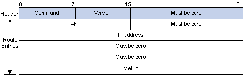
Figure 2-1 RIPv1 Message Format
l Command: Type of message. 1 indicates request, and 2 indicates response.
l Version: Version of RIP, 0x01 for RIPv1.
l AFI: Address Family Identifier, 2 for IP.
l IP Address: Destination IP address of the route. It can be a natural network, subnet or a host address.
l Metric: Cost of the route.
II. RIPv2 message format
The format of RIPv2 message is similar with RIPv1. Figure 2-2 shows it.
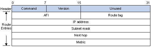
Figure 2-2 RIPv2 Message Format
The differences from RIPv1 are stated as following.
l Version: Version of RIP. For RIPv2 the value is 0x02.
l Route Tag: Route Tag.
l IP Address: Destination IP address. It could be a natural network address, subnet address or host address.
l Subnet Mask: Mask of the destination address.
l Next Hop: If set to 0.0.0.0, it indicates that the originator of the route is the best next hop; otherwise it indicates a next hop better than the originator of the route.
III. RIPv2 authentication
RIPv2 sets the AFI field of the first route entry to 0xFFFF to identify authentication information. See Figure 2-3.
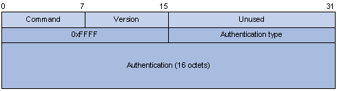
Figure 2-3 RIPv2 Authentication Message
l Authentication Type: 2 represents plain text authentication, while 3 represents MD5.
l Authentication: Authentication data, including password information when plain text authentication is adopted or including key ID, MD5 authentication data length and sequence number when MD5 authentication is adopted.
& Note:
l RFC 1723 only defines plain text authentication. For information about MD5 authentication, refer to RFC2082 “RIPv2 MD5 Authentication”.
l With RIPv1, you can configure the authentication mode in interface view. However, the configuration will not take effect because RIPv1 does not support authentication.
2.1.5 Supported RIP Features
The current implementation supports the following RIP features.
l RIPv1 and RIPv2
l RIP multi-instance.
2.1.6 Protocols and Standards
l RFC 1058: Routing Information Protocol
l RFC 1723: RIP Version 2 - Carrying Additional Information
l RFC 1721: RIP Version 2 Protocol Analysis
l RFC 1722: RIP Version 2 Protocol Applicability Statement
l RFC 1724: RIP Version 2 MIB Extension
l RFC 2082: RIPv2 MD5 Authentication
2.2 Configuring RIP Basic Functions
2.2.1 Configuration Prerequisites
Before configuring RIP basic functions, configure an IP address on each interface, and make sure all adjacent routers are reachable to each other.
2.2.2 Configuration Procedure
I. Enabling RIP and a RIP interface
Follow these steps to enable RIP:
|
Use the command… |
Remarks |
|
|
Enter system view |
system-view |
–– |
|
Enable a RIP process and enter RIP view |
rip [ process-id ] [ vpn-instance vpn-instance-name ] |
Required Not enabled by default |
|
Enable RIP on the interface attached to the specified network |
network network-address |
Required Disabled by default |
& Note:
l If you make some RIP configurations in interface view before enabling RIP, those configurations will take effect after RIP is enabled.
l RIP runs only on the interfaces residing on the specified networks. Therefore, you need to specify the network after enabling RIP to validate RIP on a specific interface.
l You can enable RIP on all interfaces using the command network 0.0.0.0.
II. Configuring the interface behavior
Follow these steps to configure the interface behavior:
|
To do… |
Use the command… |
Remarks |
|
Enter system view |
system-view |
–– |
|
Enter RIP view |
rip [ process-id ] [ vpn-instance vpn-instance-name ] |
–– |
|
Disable an or all interfaces from sending routing updates (the interfaces can still receive updates) |
silent-interface { all | interface-type interface-number } |
Optional All interfaces can send routing updates by default. |
|
Return to system view |
quit |
— |
|
Enter interface view |
interface interface-type interface-number |
— |
|
Enable the interface to receive RIP messages |
rip input |
Optional Enabled by default |
|
Enable the interface to send RIP messages |
rip output |
Optional Enabled by default |
III. Configuring a RIP version
You can configure a RIP version in RIP or interface view.
l If neither global nor interface RIP version is configured, the interface sends RIPv1 broadcasts and can receive RIPv1 broadcast and unicast packets, and RIPv2 broadcast, multicast, and unicast packets.
l If an interface has no RIP version configured, it uses the global RIP version; otherwise it uses the RIP version configured on it.
l With RIPv1 configured, an interface sends RIPv1 broadcasts, and can receive RIPv1 broadcasts and RIPv1 unicasts.
l With RIPv2 configured, a multicast interface sends RIPv2 multicasts and can receive RIPv2 unicasts, broadcasts and multicasts.
l With RIPv2 configured, a broadcast interface sends RIPv2 broadcasts and can receive RIPv1 unicasts, and broadcasts, and RIPv2 broadcasts, multicasts and unicasts.
Follow these steps to configure a RIP version:
|
To do… |
Use the command… |
Remarks |
|
Enter system view |
system-view |
–– |
|
Enter RIP view |
rip [ process-id ] [ vpn-instance vpn-instance-name ] |
–– |
|
Specify a global RIP version |
version { 1 | 2 } |
Optional; RIPv1 by default; If an interface has a RIP version specified, the version takes precedence over the global one. If no RIP version is specified for an interface, the interface can send RIPv1 broadcasts, and receive RIPv1 broadcasts, unicasts, RIPv2 broadcasts, multicasts and unicasts. |
|
Return to system view |
Quit |
— |
|
Enter interface view |
interface interface-type interface-number |
–– |
|
Specify a RIP version for the interface |
rip version { 1 | 2 [ broadcast | multicast ] } |
Optional |
2.3 Configuring RIP Route Control
In complex networks, you need to configure advanced RIP features.
This section covers the following topics:
l Configuring an Additional Routing Metric
l Configuring RIPv2 Route Summarization
l Disabling Host Route Reception
l Configuring Inbound/Outbound Route Filtering
l Configuring a Priority for RIP
l Configuring RIP Route Redistribution
Before configuring RIP routing feature, complete the following tasks:
l Configure an IP address for each interface, and make sure all neighboring routers are reachable to each other.
l Configure RIP basic functions
2.3.1 Configuring an Additional Routing Metric
An additional routing metric can be added to the metric of an inbound or outbound RIP route.
The outbound additional metric is added to the metric of a sent route, the route’s metric in the routing table is not changed.
The inbound additional metric is added to the metric of a received route before the route is added into the routing table, so the route’s metric is changed.
Follow these steps to configure additional routing metrics:
|
To do… |
Use the command… |
Remarks |
|
Enter system view |
system-view |
–– |
|
Enter interface view |
interface interface-type interface-number |
–– |
|
Define an inbound additional routing metric |
rip metricin value |
Optional 0 by default |
|
Define an outbound additional routing metric |
rip metricout value |
Optional 1 by default |
2.3.2 Configuring RIPv2 Route Summarization
Route summarization means that subnets in a natural network are summarized with a natural network that is sent to other networks. This feature can reduce the size of routing tables.
I. Enabling RIPv2 route automatic summarization
You can disable RIPv2 route automatic summarization if you want to advertise all subnet routes.
Follow these steps to enable RIPv2 route automatic summarization:
|
Use the command… |
Remarks |
|
|
Enter system view |
System-view |
–– |
|
Enter RIP view |
rip [ process-id ] [ vpn-instance vpn-instance-name ] |
–– |
|
Enable RIPv2 automatic route summarization |
summary |
Optional Enabled by default |
II. Advertising a summary route
You can configure RIPv2 to advertise a summary route on the specified interface.
To do so, use the following commands:
|
To do… |
Use the command… |
Remarks |
|
Enter system view |
system-view |
–– |
|
Enter RIP view |
rip [ process-id ] [ vpn-instance vpn-instance-name ] |
–– |
|
Disable RIPv2 automatic route summarization |
undo summary |
Required Enabled by default |
|
Return to system view |
quit |
— |
|
Enter interface view |
interface interface-type interface-number |
— |
|
Advertise a summary route |
rip summary-address ip-address { mask | mask-length } |
Required |
& Note:
You need to disable RIPv2 route automatic summarization before advertising a summary route on an interface.
2.3.3 Disabling Host Route Reception
Sometimes a router may receive many host routes from the same network, which are not helpful for routing and occupy a large amount of network resources. In this case, you can disable RIP from receiving host routes to save network resources.
Follow these steps to disable RIP from receiving host routes:
|
To do… |
Use the command… |
Remarks |
|
Enter system view |
System-view |
— |
|
Enter RIP view |
rip [ process-id ] [ vpn-instance vpn-instance-name ] |
— |
|
Disable RIP from receiving host routes |
undo host-route |
Required Enabled by default |
& Note:
RIPv2 can be disabled from receiving host routes, but RIPv1 cannot.
2.3.4 Advertising a Default Route
You can configure RIP to advertise a default route with A specified metric to RIP neighbors.
Follow these steps to configure RIP to advertise a default route:
|
To do… |
Use the command… |
Remarks |
|
Enter system view |
system-view |
–– |
|
Enter RIP view |
rip [ process-id ] [ vpn-instance vpn-instance-name ] |
–– |
|
Enable RIP to advertise a default route |
default-route originate cost value |
Required Not enabled by default |
& Note:
The router enabled to advertise a default route does not receive default routes from RIP neighbors.
2.3.5 Configuring Inbound/Outbound Route Filtering
The device supports route filtering. You can filter routes by configuring the inbound and outbound route filtering policies via referencing an ACL or IP prefix list. You can also configure the router to receive only routes from a specified neighbor.
Follow these steps to configure route filtering:
|
To do… |
Use the command… |
Remarks |
|
Enter system view |
system-view |
–– |
|
Enter RIP view |
rip [ process-id ] [ vpn-instance vpn-instance-name ] |
–– |
|
Configure the filtering of incoming routes |
filter-policy { acl-number | gateway ip-prefix-name | ip-prefix ip-prefix-name [ gateway ip-prefix-name ] } import [ interface-type interface-number ] |
Required Not configured by default |
|
Configure the filtering of outgoing routes |
filter-policy { acl-number | ip-prefix ip-prefix-name } export [ protocol [ process-id ] | interface-type interface-number ] |
Required Not configured by default |
& Note:
l Using the filter-policy import command filters incoming routes. Routes not passing the filtering will be neither installed into the routing table nor advertised to neighbors.
l Using the filter-policy export command filters outgoing routes, including routes redistributed with the import-route command.
2.3.6 Configuring a Priority for RIP
Multiple IGP protocols may run in a router. If you want RIP routes to have a higher priority than those learned by other routing protocols, you can assign RIP a smaller priority value to influence optimal route selection.
Follow these steps to configure a priority for RIP:
|
To do… |
Use the command… |
Remarks |
|
Enter system view |
system-view |
–– |
|
Enter RIP view |
rip [ process-id ] [ vpn-instance vpn-instance-name ] |
–– |
|
Configure a priority for RIP |
preference [ route-policy route-policy-name ] value |
Optional 100 by default |
2.3.7 Configuring RIP Route Redistribution
Follow these steps to configure RIP route redistribution:
|
To do… |
Use the command… |
Remarks |
|
Enter system view |
system-view |
–– |
|
Enter RIP view |
rip [ process-id ] [ vpn-instance vpn-instance-name ] |
–– |
|
Configure a default metric for redistributed routes |
default-cost value |
Optional The default metric of a redistributed route is 0 by default. |
|
Redistribute routes from another protocol |
import-route protocol [ process-id ] [ allow-ibgp ] [ cost cost | route-policy route-policy-name | tag tag ] * |
Required No redistribution is configured by default. |
2.4 Configuring RIP Network Optimization
Complete the following tasks before configuring RIP network optimization:
l Configure network addresses for interfaces, and make neighboring nodes reachable to each other;
l Configure RIP basic functions.
2.4.1 Configuring RIP Timers
Follow these steps to configure RIP timers:
|
To do… |
Use the command… |
Remarks |
|
Enter system view |
system-view |
–– |
|
Enter RIP view |
rip [ process-id ] [ vpn-instance vpn-instance-name ] |
–– |
|
Configure values for RIP timers |
timers { garbage-collect garbage-collect-value | suppress suppress-value | timeout timeout-value | update update-value }* |
Optional The default update timer, timeout timer, suppress timer, and garbage-collect timer are 30s, 180s, 120s and 120s respectively. |
& Note:
Based on network performance, you need to make RIP timers of RIP routers identical to each other to avoid unnecessary traffic or route oscillation.
2.4.2 Configuring Split Horizon and Poison Reverse
& Note:
If both split horizon and poison reverse are configured, only the poison reverse function takes effect.
I. Enabling split horizon
The split horizon function disables an interface from sending routes received from the interface to prevent routing loops between adjacent routers.
Follow these steps to enable split horizon:
|
To do… |
Use the command… |
Remarks |
|
Enter system view |
system-view |
— |
|
Enter interface view |
interface interface-type interface-number |
— |
|
Enable split horizon |
rip split-horizon |
Optional Enabled by default |
& Note:
Disabling the split horizon function on a point-to-point link does not take effect.
II. Enabling poison reverse
The poison reverse function allows an interface to advertise the routes received from it, but the metric of these routes is set to 16, making them unreachable.
Follow these steps to enable poison reverse:
|
To do… |
Use the command… |
Remarks |
|
Enter system view |
system-view |
— |
|
Enter interface view |
interface interface-type interface-number |
— |
|
Enable poison reverse |
rip poison-reverse |
Required Disabled by default |
2.4.3 Configuring the Maximum Number of Load Balanced Routes
Follow these steps to configure the maximum number of load balanced routes:
|
To do… |
Use the command… |
Remarks |
|
Enter system view |
system-view |
–– |
|
Enter RIP view |
rip [ process-id ] [ vpn-instance vpn-instance-name ] |
–– |
|
Configure the maximum number of load balanced routes |
maximum load-balancing number |
Optional 4 by default |
2.4.4 Enabling Zero Field Check on Incoming RIPv1 Messages
Some fields in the RIPv1 message must be zero. These fields are called zero fields. You can enable zero field check on received RIPv1 messages. If such a field contains a non-zero value, the RIPv1 message will not be processed. If you are sure that all messages are trusty, you can disable zero field check to save CPU resources.
Follow these steps to enable zero field check on incoming RIPv1 messages:
|
To do… |
Use the command… |
Remarks |
|
Enter system view |
system-view |
–– |
|
Enter RIP view |
rip [ process-id ] [ vpn-instance vpn-instance-name ] |
–– |
|
Enable zero field check on received RIPv1 messages |
checkzero |
Optional Enabled by default |
2.4.5 Enabling Source IP Address Check on Incoming RIP Updates
You can enable source IP address check on incoming RIP updates.
For a message received on an Ethernet interface, RIP compares the source IP address of the message with the IP address of the interface. If they are not in the same network segment, RIP discards the message.
For a message received on a serial interface, RIP checks whether the source address of the message is the IP address of the peer interface. If not, RIP discards the message.
Follow these steps to enable source IP address check on incoming RIP updates:
|
To do… |
Use the command… |
Remarks |
|
Enter system view |
system-view |
–– |
|
Enter RIP view |
rip [ process-id ] [ vpn-instance vpn-instance-name ] |
–– |
|
Enable source IP address check on incoming RIP messages |
validate-source-address |
Optional Enabled by default |
& Note:
The source IP address check feature should be disabled if a RIP neighbor is not directly connected.
2.4.6 Configuring RIPv2 Message Authentication
RIPv2 supports two authentication modes: plain text and MD5.
In plain text authentication, the authentication information is sent with the RIP message, which however cannot meet high security needs.
Follow these steps to configure RIPv2 message authentication:
|
To do… |
Use the command… |
Remarks |
|
Enter system view |
system-view |
–– |
|
Enter interface view |
interface interface-type interface-number |
–– |
|
Configure RIPv2 authentication |
rip authentication-mode { md5 { rfc2082 key-string key-id | rfc2453 key-string } | simple password } |
Required |
2.4.7 Specifying a RIP Neighbor
Usually, RIP sends messages to broadcast or multicast addresses. On non broadcast or multicast links, you need to manually specify RIP neighbors. If a specified neighbor is not directly connected, you must disable source address check on incoming updates.
Follow these steps to specify a RIP neighbor:
|
To do… |
Use the command… |
Remarks |
|
Enter system view |
system-view |
–– |
|
Enter RIP view |
rip [ process-id ] [ vpn-instance vpn-instance-name ] |
–– |
|
Specify a RIP neighbor |
peer ip-address |
Required Not specified by default |
|
Disable source address check on incoming RIP updates |
undo validate-source-address |
Required Not disabled by default |
& Note:
You need not use the peer ip-address command when the neighbor is directly connected; otherwise the neighbor may receive both the unicast and multicast (or broadcast) of the same routing information.
2.4.8 Configuring RIP-to-MIB Binding
Follow these steps to bind RIP to MIB:
|
To do… |
Use the command… |
Remarks |
|
Enter system view |
system-view |
–– |
|
Bind RIP to MIB |
rip mib-binding process-id |
Optional By default, MIB is bound to the RIP process with the smallest process ID |
2.5 Displaying and Maintaining RIP
|
Use the command… |
Remarks |
|
|
Display RIP current status and configuration information |
display rip [ process-id | vpn-instance vpn-instance-name ] |
Available in any view |
|
Display all active routes in RIP database |
display rip process-id database |
|
|
Display RIP interface information |
display rip process-id interface [ interface-type interface-number ] |
|
|
Display routing information about a specified RIP process |
display rip process-id route [ statistics | ip-address { mask | mask-length } | peer ip-address ] |
|
|
Clear the statistics of a RIP process |
reset rip process-id statistics |
Available in user view |
2.6 RIP Configuration Examples
2.6.1 Configuring RIP Version
I. Network requirements
As shown in Figure 2-4, enable RIPv2 on all interfaces on Switch A and Switch B.
II. Network diagram
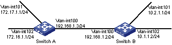
Figure 2-4 Network diagram for RIP version configuration
III. Configuration procedure
1) Configure an IP address for each interface (omitted)
2) Configure basic RIP functions
# Configure Switch A.
<SwitchA> system-view
[SwitchA] rip
[SwitchA-rip-1] network 192.168.1.0
[SwitchA-rip-1] network 172.16.0.0
[SwitchA-rip-1] network 172.17.0.0
[SwitchA-rip-1] quit
# Configure Switch B.
<SwitchB> system-view
[SwitchB] rip
[SwitchB-rip-1] network 192.168.1.0
[SwitchB-rip-1] network 10.0.0.0
[SwitchB-rip-1] quit
# Display the RIP routing table of Switch A.
[SwitchA] display rip 1 route
Route Flags: R - RIP, T - TRIP
P - Permanent, A - Aging, S - Suppressed, G - Garbage-collect
--------------------------------------------------------------------------
Peer 192.168.1.2 on Vlan-interface100
Destination/Mask Nexthop Cost Tag Flags Sec
10.0.0.0/8 192.168.1.2 1 0 RA 11
From the routing table, you can find RIPv1 uses natural mask.
3) Configure RIP version
# Configure RIPv2 on Switch A.
[SwitchA] rip
[SwitchA-rip-1] version 2
[SwitchA-rip-1] undo summary
# Configure RIPv2 on Switch B.
[SwitchB] rip
[SwitchB-rip-1] version 2
[SwitchB-rip-1] undo summary
# Display the RIP routing table on Switch A.
[SwitchA] display rip 1 route
Route Flags: R - RIP, T - TRIP
P - Permanent, A - Aging, S - Suppressed, G - Garbage-collect
--------------------------------------------------------------------------
Peer 192.168.1.2 on Vlan-interface100
Destination/Mask Nexthop Cost Tag Flags Sec
10.2.1.0/24 192.168.1.2 1 0 RA 16
10.1.1.0/24 192.168.1.2 1 0 RA 16
From the routing table, you can see RIPv2 uses classless subnet mask.
& Note:
Since RIPv1 routing information has a long aging time, it will still exist until aged out after RIPv2 is configured.
2.6.2 Configuring RIP Route Redistribution
I. Network requirements
As shown in Figure 2-5, two RIP processes are running on Switch B, which communicates with Switch A through RIP100 and with Switch C through RIP 200.
Configure route redistribution on Switch B, letting the two RIP processes redistribute routes from each other. Set the cost of redistributed routes from RIP 200 to 3. Configure a filtering policy on Switch B to filter out the route 4.1.1.1/24 from RIP200, making the route not advertised to Switch A.
II. Network diagram
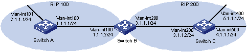
Figure 2-5 Network diagram for RIP route redistribution configuration
III. Configuration procedure
1) Configure an IP address for each interface (Omitted).
2) Configure basic RIP functions.
# Enable RIP 100 and specify RIP version 2 on Switch A.
<SwitchA> system-view
[SwitchA] rip 100
[SwitchA-rip-100] network 1.0.0.0
[SwitchA-rip-100] network 2.0.0.0
[SwitchA-rip-100] version 2
[SwitchA-rip-100] undo summary
[SwitchA-rip-100] quit
# Enable RIP 100 and RIP 200 and specify RIP version 2 on Switch B.
<SwitchB> system-view
[SwitchB] rip 100
[SwitchB-rip-100] network 1.0.0.0
[SwitchB-rip-100] version 2
[SwitchB-rip-100] undo summary
[SwitchB-rip-100] quit
[SwitchB] rip 200
[SwitchB-rip-200] network 3.0.0.0
[SwitchB-rip-200] version 2
[SwitchB-rip-200] undo summary
[SwitchB-rip-200] quit
# Enable RIP 200 and specify RIP version 2 on Switch C.
<SwitchC> system-view
[SwitchC] rip 200
[SwitchC-rip-200] network 3.0.0.0
[SwitchC-rip-200] network 4.0.0.0
[SwitchC-rip-200] network 5.0.0.0
[SwitchC-rip-200] version 2
[SwitchC-rip-200] undo summary
# Display the routing table of Switch A.
[SwitchA] display ip routing-table
Routing Tables: Public
Destinations : 6 Routes : 6
Destination/Mask Proto Pre Cost NextHop Interface
1.1.1.0/24 Direct 0 0 1.1.1.1 Vlan100
1.1.1.1/32 Direct 0 0 127.0.0.1 InLoop0
2.1.1.0/24 Direct 0 0 2.1.1.1 Vlan101
2.1.1.1/32 Direct 0 0 127.0.0.1 InLoop0
127.0.0.0/8 Direct 0 0 127.0.0.1 InLoop0
127.0.0.1/32 Direct 0 0 127.0.0.1 InLoop0
3) Configure route redistribution
# Configure route redistribution between the two RIP processes on Switch B.
[SwitchB] rip 100
[SwitchB-rip-100] default cost 3
[SwitchB-rip-100] import-route rip 200
[SwitchB-rip-100] quit
[SwitchB] rip 200
[SwitchB-rip-200] import-route rip 100
[SwitchB-rip-200] quit
# Display the routing table of Switch A.
[SwitchA] display ip routing-table
Routing Tables: Public
Destinations : 9 Routes : 9
Destination/Mask Proto Pre Cost NextHop Interface
1.1.1.0/24 Direct 0 0 1.1.1.1 Vlan100
1.1.1.1/32 Direct 0 0 127.0.0.1 InLoop0
2.1.1.0/24 Direct 0 0 2.1.1.1 Vlan101
2.1.1.1/32 Direct 0 0 127.0.0.1 InLoop0
3.1.1.0/24 RIP 100 4 1.1.1.2 Vlan100
4.1.1.0/24 RIP 100 4 1.1.1.2 Vlan100
5.1.1.0/24 RIP 100 4 1.1.1.2 Vlan100
127.0.0.0/8 Direct 0 0 127.0.0.1 InLoop0
127.0.0.1/32 Direct 0 0 127.0.0.1 InLoop0
4) Configure an filtering policy to filter redistributed routes
# Define ACL 2000 and reference it to a filtering policy to filter routes redistributed from RIP 200 on Switch B.
[SwitchB] acl number 2000
[SwitchB-acl-basic-2000] rule deny source 4.1.1.1 0.0.0.255
[SwitchB-acl-basic-2000] rule permit
[SwitchB-acl-basic-2000] quit
[SwitchB] rip 100
[SwitchB-rip-100] filter-policy 2000 export rip 200
# Display the routing table of Switch A.
[SwitchA] display ip routing-table
Routing Tables: Public
Destinations : 8 Routes : 8
Destination/Mask Proto Pre Cost NextHop Interface
1.1.1.0/24 Direct 0 0 1.1.1.1 Vlan100
1.1.1.1/32 Direct 0 0 127.0.0.1 InLoop0
2.1.1.0/24 Direct 0 0 2.1.1.1 Vlan101
2.1.1.1/32 Direct 0 0 127.0.0.1 InLoop0
3.1.1.0/24 RIP 100 4 1.1.1.2 Vlan100
5.1.1.0/24 RIP 100 4 1.1.1.2 Vlan100
127.0.0.0/8 Direct 0 0 127.0.0.1 InLoop0
127.0.0.1/32 Direct 0 0 127.0.0.1 InLoop0
2.7 Troubleshooting RIP
2.7.1 No RIP Updates Received
Symptom:
No RIP updates are received when the links work well.
Analysis:
After enabling RIP, you must use the network command to enable corresponding interfaces. Make sure no interfaces are disabled from handling RIP messages.
If the peer is configured to send multicast messages, the same should be configured on the local end.
Solution:
l Use the display current-configuration command to check RIP configuration
l Use the display rip command to check whether some interface is disabled
2.7.2 Route Oscillation Occurred
Symptom:
When all links work well, route oscillation occurs on the RIP network. After displaying the routing table, you may find some routes appear and disappear in the routing table intermittently.
Analysis:
In the RIP network, make sure all the same timers within the whole network are identical and relationships between timers are reasonable. For example, the timeout timer value should be larger than the update timer value.
Solution:
l Use the display rip command to check the configuration of RIP timers
l Use the timers command to adjust timers properly.
Chapter 3 OSPF Configuration
Open Shortest Path First (OSPF) is a link state interior gateway protocol developed by the OSPF working group of the Internet Engineering Task Force (IETF). At present, OSPF version 2 (RFC2328) is used.
When configuring OSPF, go to these sections for information you are interested in:
l OSPF Configuration Task List
l Configuring OSPF Basic Functions
l Configuring OSPF Area Parameters
l Configuring OSPF Network Types
l Configuring OSPF Route Control
l Configuring OSPF Network Optimization
l Configuring OSPF Graceful Restart
l Displaying and Maintaining OSPF
l Troubleshooting OSPF Configuration
& Note:
l The term “router” in this document refers to a router in a generic sense or an Ethernet switch running routing protocols.
l The value ranges of the parameters of the commands in this manual use the ranges assuming the switch operate in the default mode. When the switch operates in the IPv4/IPv6 dual-stack or the MCE mode, the value ranges of some parameters may vary. For the operating modes of the switch, refer to the parts discussing IPv6 configuration or MCE.
3.1 Introduction to OSPF
& Note:
Unless otherwise noted, OSPF refers to OSPFv2 throughout this document.
OSPF has the following features:
l Wide scope: Supports networks of various sizes and up to several hundred routers in an OSPF routing domain.
l Fast convergence: Transmits updates instantly after network topology changes for routing information synchronization in the AS.
l Loop-free: Computes routes with the shortest path first (SPF) algorithm according to the collected link states, so no route loops are generated.
l Area partition: Allows an AS to be split into different areas for ease of management and the routing information transmitted between areas is summarized to reduce network bandwidth consumption.
l Equal-cost multi-route: Supports multiple equal-cost routes to a destination.
l Routing hierarchy: Supports a four-level routing hierarchy that prioritizes the routes into intra-area, inter-area, external Type-1, and external Type-2 routes.
l Authentication: Supports interface-based packet authentication to guarantee the security of packet exchange.
l Multicast: Supports packet multicasting on some types of links.
3.1.1 Basic Concepts
I. Autonomous System
A set of routers using the same routing protocol to exchange routing information constitute an Autonomous System (AS).
II. OSPF route computation
OSPF route computation is described as follows:
l Based on the network topology around itself, each router generates Link State Advertisements (LSA) and sends them to other routers in update packets.
l Each OSPF router collects LSAs from other routers to compose a LSDB (Link State Database). An LSA describes the network topology around a router, so the LSDB describes the entire network topology of the AS.
l Each router transforms the LSDB to a weighted directed graph, which actually reflects the topology architecture of the entire network. All the routers have the same graph.
l Each router uses the SPF algorithm to compute a Shortest Path Tree that shows the routes to the nodes in the autonomous system. The router itself is the root of the tree.
III. Router ID
To run OSPF, a router must have a Router ID, which is a 32-bit unsigned integer, the unique identifier of the router in the AS.
You may assign a Router ID to an OSPF router manually. If no Router ID is specified, the system automatically selects one for the router as follows:
l If the loopback interfaces are configured, select the highest IP address among them.
l If no loopback interface is configured, select the highest IP address among addresses of active interfaces on the router.
IV. OSPF packets
OSPF uses five types of packets:
l Hello packet: Periodically sent to find and maintain neighbors, containing the values of some timers, information about the DR, BDR and known neighbors.
l DD packet (database description packet): Describes the digest of each LSA in the LSDB, exchanged between two routers for data synchronization.
l LSR (link state request) packet: Requests needed LSAs from the neighbor. After exchanging the DD packets, the two routers know which LSAs of the neighbor are missing from the local LSDBs. In this case, they send an LSR packet to each other, requesting the missing LSAs. The LSA packet contains the digest of the missing LSAs.
l LSU (link state update) packet: Transmits the needed LSAs to the neighbor.
l LSAck (link state acknowledgment) packet: Acknowledges received LSU packets. It contains the headers of received LSAs (a packet can acknowledge multiple LSAs).
V. LSA types
OSPF sends routing information in LSAs, which, as defined in RFC 2328, have the following types:
l Router LSA: Type-1 LSA, originated by all routers, flooded throughout a single area only. This LSA describes the collected states of the router's interfaces to an area.
l Network LSA: Type-2 LSA, originated for broadcast and NBMA networks by the designated router, flooded throughout a single area only. This LSA contains the list of routers connected to the network.
l Network Summary LSA: Type-3 LSA, originated by ABRs (Area Border Routers), and flooded throughout the LSA's associated area. Each summary-LSA describes a route to a destination outside the area, yet still inside the AS (an inter-area route).
l ASBR Summary LSA: Type-4 LSA, originated by ABRs and flooded throughout the LSA's associated area. Type 4 summary-LSAs describe routes to ASBR (Autonomous System Boundary Router).
l AS External LSA: Type-5 LSA, originated by ASBRs, and flooded throughout the AS (except stub and NSSA areas). Each AS-external-LSA describes a route to another AS.
l NSSA LSA: Type-7 LSA, as defined in RFC 1587, originated by ASBRs in NSSAs (Not-So-Stubby Areas) and flooded throughout a single NSSA. NSSA LSAs describe routes to other ASs.
l Opaque LSA: A proposed type of LSA, the format of which consists of a standard LSA header and application specific information. Opaque LSAs are used by the OSPF protocol or by some application to distribute information into the OSPF routing domain. The opaque LSA includes three types, Type 9, Type 10 and Type 11, which are used to flood into different areas. The Type 9 opaque LSA is flooded into the local subnet, the Type 10 is flooded into the local area, and the Type 11 is flooded throughout the whole AS.
VI. Neighbor and Adjacency
In OSPF, the “Neighbor” and ”Adjacency” are two different concepts.
Neighbor: Two routers that have interfaces to a common network. Neighbor relationships are maintained by, and usually dynamically discovered by, OSPF's hello packets. When a router starts, it sends a hello packet via the OSPF interface, and the router that receives the hello packet checks parameters carried in the packet. If parameters of the two routers match, they become neighbors.
Adjacency: A relationship formed between selected neighboring routers for the purpose of exchanging routing information. Not every pair of neighboring routers become adjacent, which depends on network types. Only by synchronizing the LSDB via exchanging DD packets and LSAs can two routers become adjacent.
3.1.2 OSPF Area Partition and Route Summarization
I. Area partition
When a large number of OSPF routers are present on a network, LSDBs may become so large that a great amount of storage space is occupied and CPU resources are exhausted by performing SPF computation.
In addition, as the topology of a large network is prone to changes, enormous OSPF packets may be created, reducing bandwidth utilization. Each topology change makes all routers perform route calculation.
To solve this problem, OSPF splits an AS into multiple areas, which are identified by area ID. The boundaries between areas are routers rather than links. A network segment (or a link) can only reside in one area, in other words, an OSPF interface must be specified to belong to its attached area, as shown in the figure below.
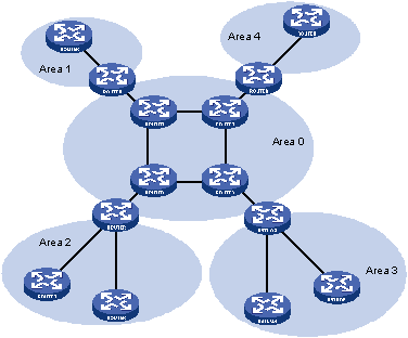
Figure 3-1 OSPF area partition
After area partition, area border routers perform route summarization to reduce the number of LSAs advertised to other areas and minimize the effect of topology changes.
II. Classification of Routers
The OSPF routers fall into four types according to the position in the AS:
1) Internal Router
All interfaces on an internal router belong to one OSPF area.
2) Area Border Router (ABR)
An area border router belongs to more than two areas, one of which must be the backbone area. It connects the backbone area to a non-backbone area. The connection between an area border router and the backbone area can be physical or logical.
3) Backbone Router
At least one interface of a backbone router must be attached to the backbone area. Therefore, all ABRs and internal routers in area 0 are backbone routers.
4) Autonomous System Border Router (ASBR)
The router exchanging routing information with another AS is an ASBR, which may not reside on the boundary of the AS. It can be an internal router or area border router.
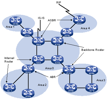
Figure 3-2 OSPF router types
III. Backbone area and virtual links
Each AS has a backbone area, which is responsible for distributing routing information between none-backbone areas. Routing information between non-backbone areas must be forwarded by the backbone area. Therefore, OSPF requires that:
l All non-backbone areas must maintain connectivity to the backbone area.
l The backbone area itself must maintain connectivity.
In practice, due to physical limitations, the requirements may not be satisfied. In this case, configuring OSPF virtual links is a solution.
A virtual link is established between two area border routers via a non-backbone area and is configured on both ABRs to take effect. The area that provides the non-backbone area internal route for the virtual link is a “transit area”.
In the following figure, Area 2 has no direct physical link to the backbone area 0. Configuring a virtual link between ABRs can connect Area 2 to the backbone area.
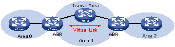
Figure 3-3 Virtual link application 1
Another application of virtual links is to provide redundant links. If the backbone area cannot maintain internal connectivity due to a physical link failure, configuring a virtual link can guarantee logical connectivity in the backbone area, as shown below.
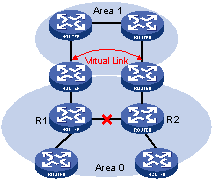
Figure 3-4 Virtual link application 2
The virtual link between the two ABRs acts as a point-to-point connection. Therefore, you can configure interface parameters such as hello packet interval on the virtual link as they are configured on physical interfaces.
The two ABRs on the virtual link exchange OSPF packets with each other directly, and the OSPF routers in between simply convey these OSPF packets as normal IP packets.
IV. (Totally) Stub area
The ABR in a stub area does not distribute Type-5 LSAs into the area, so the routing table size and amount of routing information in this area are reduced significantly.
You can configure the stub area as a totally stub area, where the ABR advertises neither the destinations in other areas nor the external routes.
Stub area configuration is optional, and not every area is eligible to be a stub area. In general, a stub area resides on the border of the AS.
The ABR in a stub area generates a default route into the area.
Note the following when configuring a (totally) stub area:
l The backbone area cannot be a (totally) stub area.
l The stub command must be configured on routers in a (totally) stub area.
l A (totally) stub area cannot have an ASBR because AS external routes cannot be distributed into the stub area.
l Virtual links cannot transit (totally) stub areas.
V. NSSA area
Similar to a stub area, an NSSA area imports no AS external LSA (Type-5 LSA) but can import Type-7 LSAs that are generated by the ASBR and distributed throughout the NSSA area. When traveling to the NSSA ABR, Type-7 LSAs are translated into Type-5 LSAs by the ABR for advertisement to other areas.
In the following figure, the OSPF AS contains three areas: Area 1, Area 2 and Area 0. The other two ASs employ the RIP protocol. Area 1 is an NSSA area, and the ASBR in it translates RIP routes into Type-7 LSAs and advertises them throughout Area 1. When these LSAs travel to the NSSA ABR, the ABR translates Type-7 LSAs to Type-5 LSAs for advertisement to Area 0 and Area 2.
On the left of the figure, RIP routes are translated into Type-5 LSAs by the ASBR of Area 2 and distributed into the OSPF AS. However, Area 1 is an NSSA area, so these Type-5 LSAs cannot travel to Area 1.
Like stub areas, virtual links cannot transit NSSA areas.
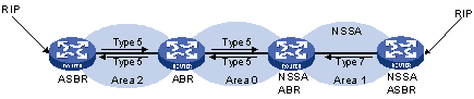
Figure 3-5 NSSA area
VI. Route summarization
Route summarization: An ABR or ASBR summarizes routes with the same prefix with a single route and distribute it to other areas.
Via route summarization, routing information across areas and the size of routing tables on routers will be reduced, improving calculation speed of routers.
For example, as shown in the following figure, in Area 1 are three internal routes 19.1.1.0/24, 19.1.2.0/24, and 19.1.3.0/24. By configuring route summarization on Router A, the three routes are summarized with the route 19.1.0.0/16 that is advertised into Area 0.
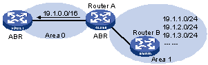
Figure 3-6 Route summarization
OSPF has two types of route summarization:
1) ABR route summarization
To distribute routing information to other areas, an ABR generates Type-3 LSAs on a per network segment basis for an attached non-backbone area. If contiguous network segments are available in the area, you can summarize them with a single network segment. The ABR in the area distributes only the summary LSA to reduce the scale of LSDBs on routers in other areas.
2) ASBR route summarization
If summarization for redistributed routes is configured on an ASBR, it will summarize redistributed Type-5 LSAs that fall into the specified address range. If in an NSSA area, it also summarizes Type-7 LSAs that fall into the specified address range.
If this feature is configured on an ABR, the ABR will summarize Type-5 LSAs translated from Type-7 LSAs.
VII. Route types
OSPF prioritize routes into four levels:
l Intra-area route
l Inter-area route
l Type-1 external route
l Type-2 external route
The intra-area and inter-area routes describe the network topology of the AS, while external routes describe routes to destinations outside the AS.
OSPF classifies external routes into two types: Type-1 and Type-2. A Type-1 external route is an IGP route, such as a RIP or static route, which has high credibility and whose cost is comparable with the cost of an OSPF internal route. The cost from a router to the destination of the Type-1 external route= the cost from the router to the corresponding ASBR+ the cost from the ASBR to the destination of the external route.
A Type-2 external route is an EGP route, which has low credibility, so OSPF considers the cost from the ASBR to the destination of the Type-2 external route is much bigger than the cost from the ASBR to an OSPF internal router. Therefore, the cost from the internal router to the destination of the Type-2 external route= the cost from the ASBR to the destination of the Type-2 external route. If two routes to the same destination have the same cost, then take the cost from the router to the ASBR into consideration.
3.1.3 Classification of OSPF Networks
I. OSPF network types
OSPF classifies networks into four types upon the link layer protocol:
l Broadcast: When the link layer protocol is Ethernet or FDDI, OSPF considers the network type broadcast by default. On Broadcast networks, packets are sent to multicast addresses (such as 224.0.0.5 and 224.0.0.6).
l NBMA (Non-Broadcast Multi-Access): When the link layer protocol is Frame Relay, ATM or X.25, OSPF considers the network type as NBMA by default. Packets on these networks are sent to unicast addresses.
l P2MP (point-to-multipoint): By default, OSPF considers no link layer protocol as P2MP, which is a conversion from other network types such as NBMA in general. On P2MP networks, packets are sent to multicast addresses (224.0.0.5).
l P2P (point-to-point): When the link layer protocol is PPP or HDLC, OSPF considers the network type as P2P. On P2P networks, packets are sent to multicast addresses (224.0.0.5).
II. NBMA network configuration principle
Typical NBMA networks are ATM and Frame Relay networks.
You need to perform some special configuration on NBMA interfaces. Since these interfaces cannot broadcast hello packets for neighbor location, you need to specify neighbors manually and configure whether the neighbors have the DR election right.
An NBMA network is fully meshed, which means any two routers in the NBMA network have a direct virtual link for communication. If direct connections are not available between some routers, the type of interfaces associated should be configured as P2MP, or as P2P for interfaces with only one neighbor.
Differences between NBMA and P2MP networks:
l NBMA networks are fully meshed, non-broadcast and multi access. P2MP networks are not required to be fully meshed.
l It is required to elect the DR and BDR on NBMA networks, while DR and BDR are not available on P2MP networks.
l NBMA is the default network type, while P2MP is a conversion from other network types, such as NBMA in general.
l On NBMA networks, packets are unicast, and neighbors are configured manually on routers. On P2MP networks, packets are multicast.
3.1.4 DR and BDR
I. DR/BDR introduction
On broadcast or NBMA networks, any two routers exchange routing information with each other. If n routers are present on a network, n(n-1)/2 adjacencies are required. Any change on a router in the network generates traffic for routing information synchronization, consuming network resources. The Designated Router is defined to solve the problem. All other routers on the network send routing information to the DR, which is responsible for advertising link state information.
If the DR fails to work, routers on the network have to elect another DR and synchronize information with the new DR. It is time-consuming and prone to routing calculation errors. The Backup Designated Router (BDR) is introduced to reduce the synchronization period.
The BDR is elected along with the DR and establishes adjacencies for routing information exchange with all other routers. When the DR fails, the BDR will become the new DR in a very short period by avoiding adjacency establishment and DR reelection. Meanwhile, other routers elect another BDR, which requires a relatively long period but has no influence on routing calculation.
Other routers, also known as DRothers, establish no adjacency and exchange no routing information with each other, thus reducing the number of adjacencies on broadcast and NBMA networks.
In the following figure, real lines are Ethernet physical links, and dashed lines represent adjacencies. With the DR and BDR in the network, only seven adjacencies are enough.
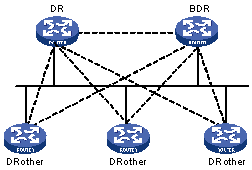
Figure 3-7 DR and BDR in a network
II. DR/BDR election
The DR and BDR in a network are elected by all routers rather than configured manually. The DR priority of an interface determines its qualification for DR/BDR election. Interfaces attached to the network and having priorities higher than ‘0” are election candidates.
The election votes are hello packets. Each router sends the DR elected by itself in a hello packet to all the other routers. If two routers on the network declare themselves as the DR, the router with the higher DR priority wins. If DR priorities are the same, the router with the higher router ID wins. In addition, a router with the priority 0 cannot become the DR/BDR.
Note that:
l The DR election is available on broadcast, NBMA interfaces rather than P2P, or P2MP interfaces.
l A DR is an interface of a router and belongs to a single network segment. The router’s other interfaces may be a BDR or DRother.
l After DR/BDR election and then a new router joins, it cannot become the DR immediately even if it has the highest priority on the network.
l The DR may not be the router with the highest priority in a network, and the BDR may not be the router with the second highest priority.
3.1.5 OSPF Packet Formats
OSPF packets are directly encapsulated into IP packets. OSPF has the IP protocol number 89. The OSPF packet format is shown below (taking a LSU packet as an example).
![]()
Figure 3-8 OSPF packet format
I. OSPF packet header
OSPF packets are classified into five types that have the same packet header, as shown below.
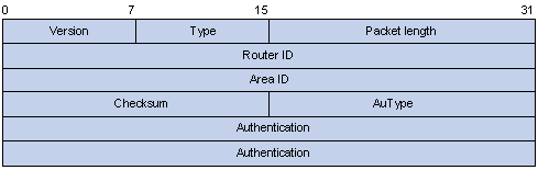
Figure 3-9 OSPF packet header
l Version: OSPF version number, which is 2 for OSPFv2.
l Type: OSPF packet type from 1 to 5, corresponding with hello, DD, LSR, LSU and LSAck respectively.
l Packet length: Total length of the OSPF packet in bytes, including the header.
l Router ID: ID of the advertising router.
l Area ID: ID of the area where the advertising router resides.
l Checksum: Checksum of the message.
l Autype: Authentication type from 0 to 2, corresponding with non-authentication, simple (plaintext) authentication and MD5 authentication respectively.
l Authentication: Information determined by authentication type. It is not defined for authentication type 0. It is defined as password information for authentication type 1, and defined as Key ID, MD5 authentication data length and sequence number for authentication type 2.
& Note:
MD5 authentication data is added following an OSPF packet rather than contained in the Authentication field.
II. Hello packet
A router sends hello packets periodically to neighbors to find and maintain neighbor relationships and to elect the DR/BDR, including information about values of timers, DR, BDR and neighbors already known. The format is shown below:
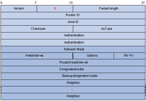
Figure 3-10 Hello packet format
Major fields:
l Network Mask: Network mask associated with the router’s sending interface. If two routers have different network masks, they cannot become neighbors.
l HelloInterval: Interval for sending hello packets. If two routers have different intervals, they cannot become neighbors.
l Rtr Pri: Router priority. A value of 0 means the router cannot become the DR/BDR.
l RouterDeadInterval: Time before declaring a silent router down. If two routers have different time values, they cannot become neighbors.
l Designated Router: IP address of the DR interface.
l Backup Designated Router: IP address of the BDR interface
l Neighbor: Router ID of the neighbor router.
III. DD packet
Two routers exchange database description (DD) packets describing their LSDBs for database synchronization, contents in DD packets including the header of each LSA (uniquely representing a LSA). The LSA header occupies small part of an LSA to reduce traffic between routers. The recipient checks whether the LSA is available using the LSA header.
The DD packet format:
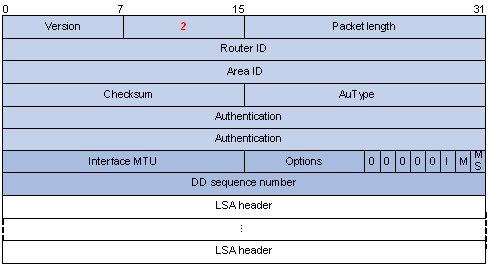
Figure 3-11 DD packet format
Major fields:
l Interface MTU: Size in bytes of the largest IP datagram that can be sent out the associated interface, without fragmentation.
l I (Initial) The Init bit, which is set to 1 if the packet is the first packet of database description packets, and set to 0 if not.
l M (More): The More bit, which is set to 0 if the packet is the last packet of DD packets, and set to 1 if more DD Packets are to follow.
l MS (Master/Slave): The Master/Slave bit. When set to 1, it indicates that the router is the master during the database exchange process. Otherwise, the router is the slave.
l DD Sequence Number: Used to sequence the collection of database description packets for ensuring reliability and intactness of DD packets between the master and slave. The initial value is set by the master. The DD sequence number then increments until the complete database description has been sent.
IV. LSR packet
After exchanging DD packets, any two routers know which LSAs of the peer routers are missing from the local LSDBs. In this case, they send LSR (link state request) packets, requesting the missing LSAs. The packets contain the digests of the missing LSAs. The following figure shows the LSR packet format.
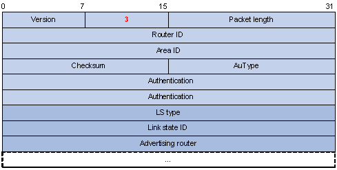
Figure 3-12 LSR packet format
Major fields:
l LS type: Type number of the LSA to be requested. Type 1 for example indicates the Router LSA.
l Link State ID: Determined by LSA type.
l Advertising Router: ID of the router that sent the LSA.
V. LSU packet
LSU (Link State Update) packets are used to send the requested LSAs to peers, and each packet carries a collection of LSAs. The LSU packet format is shown below.
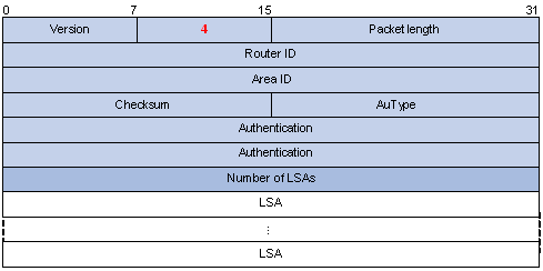
Figure 3-13 LSU packet format
VI. LSAck packet
LSAack (Link State Acknowledgment) packets are used to acknowledge received LSU packets, contents including LSA headers to describe the corresponding LSAs. Multiple LSAs can be acknowledged in a single Link State Acknowledgment packet. The following figure gives its format.
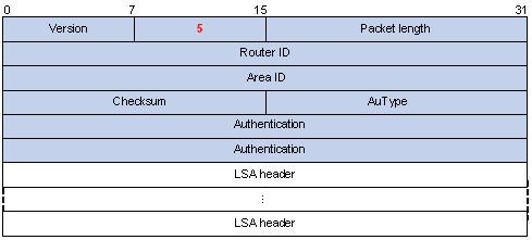
Figure 3-14 LSAck packet format
VII. LSA header format
All LSAs have the same header, as shown in the following figure.

Figure 3-15 LSA header format
Major fields:
l LS age: Time in seconds elapsed since the LSA was originated. A LSA ages in the LSDB (added by 1 per second), but does not in transmission.
l LS type: Type of the LSA.
l Link State ID: The contents of this field depend on the LSA's type
l LS sequence number: Used by other routers to judge new and old LSAs.
l LS checksum: Checksum of the LSA except the LS age field.
l Length: Length in bytes of the LSA, including the LSA header.
VIII. Formats of LSAs
1) Router LSA
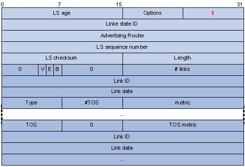
Figure 3-16 Router LSA format
Major fields:
l Link State ID: ID of the router that originated the LSA.
l V (Virtual Link): Set to 1 if the router that originated the LSA is a virtual link endpoint.
l E (External): Set to 1 if the router that originated the LSA is an ASBR.
l B (Border): Set to 1 if the router that originated the LSA is an ABR.
l # links: Number of router links (interfaces) to the area, described in the LSA.
l Link ID: Determined by Link type.
l Link Data: Determined by Link type.
l Type: Link type. A value of 1 indicates a point-to-point link to a remote router; a value of 2 indicates a link to a transit network; a value of 3 indicates a link to a stub network; a value of 4 indicates a virtual link.
l #TOS: Number of different TOS metrics given for this link.
l metric: Cost of using this router link.
l TOS: IP Type of Service that this metric refers to.
l TOS metric: TOS-specific metric information.
2) Network LSA
A Network LSA is originated by the DR on a broadcast or NBMA network. The LSA describes all routers attached to the network.
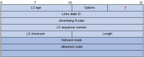
Figure 3-17 Network LSA format
Major fields:
l Link State ID: The interface address of the DR
l Network Mask: The mask of the network (a broadcast or NBMA network)
l Attached Router: The IDs of the routers, which are adjacent to the DR, including the DR itself
3) Summary LSA
Network summary LSAs (Type-3 LSAs) and ASBR summary LSAs (Type-4 LSAs) are originated by ABRs. Other than the difference in the Link State ID field, the format of type 3 and 4 summary-LSAs is identical.
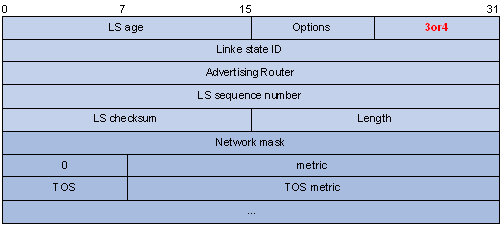
Figure 3-18 Summary LSA format
Major fields:
l Link State ID: For a Type-3 LSA, it is an IP address outside the area; for a type 4 LSA, it is the router ID of an ASBR outside the area.
l Network Mask: The network mask for the type 3 LSA; set to 0.0.0.0 for the Type-4 LSA
l metric: The metric to the destination
& Note:
A Type-3 LSA can be used to advertise a default route, having the Link State ID and Network Mask set to 0.0.0.0.
4) AS external LSA
An AS external LSA originates from an ASBR, describing routing information to a destination outside the AS.
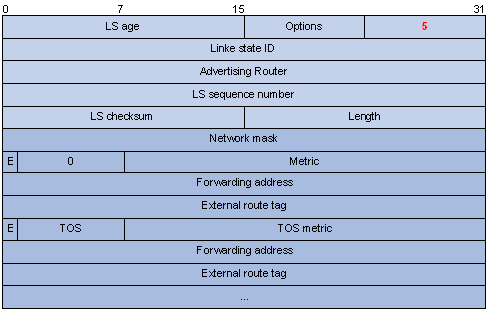
Figure 3-19 AS external LSA format
Major fields:
l Link State ID: The IP address of another AS to be advertised. When describing a default route, the Link State ID is always set to Default Destination (0.0.0.0) and the Network Mask is set to 0.0.0.0
l Network Mask: The IP address mask for the advertised destination
l E (External Metric): The type of the external metric value, which is set to 1 for type 2 external routes, and set to 0 for type 1 external routes. Refer to Route types for description about external route types
l metric: The metric to the destination
l Forwarding Address: Data traffic for the advertised destination will be forwarded to this address
l External Route Tag: A tag attached to each external route. This is not used by the OSPF protocol itself. It may be used to manage external routes.
5) NSSA external LSA
An NSSA external LSA originates from the ASBR in a NSSA and is flooded in the NSSA area only. It has the same format as the AS external LSA.
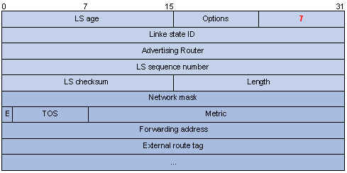
Figure 3-20 NSSA external LSA format
3.1.6 Supported OSPF Features
I. Multi-process
With multi-process support, multiple OSPF processes can run on a router simultaneously and independently. Routing information interactions between different processes seem like interactions between different routing protocols. Multiple OSPF processes can use the same RID.
An interface of a router can only belong to a single OSPF process.
II. Authentication
OSPF supports authentication on packets. Only packets that pass the authentication are received. If hello packets cannot pass authentication, no neighbor relationship can be established.
The authentication type for interfaces attached to a single area must be identical. Authentication types include non-authentication, plaintext authentication and MD5 ciphertext authentication. The authentication password for interfaces attached to a network segment must be identical.
III. OSPF Graceful Restart
& Note:
For GR information, refer to BFD-GR.
After an OSPF GR Restarter restarts OSPF, it needs to perform the following two tasks in order to re-synchronize its LSDB with its neighbors.
l To obtain once again effective OSPF neighbor information, supposing the adjacencies are not changed.
l To obtain once again LSDB contents.
Before the restart, the GR Restarter originates Grace-LSAs to negotiate the GR capability. During the restart, the GR Helpers continue to advertise their adjacencies with the GR Restarter.
After the restart, the GR Restarter will send an OSPF GR signal to its neighbors that will not reset their adjacencies with it. In this way, the GR Restarter can restore the neighbor table upon receiving the responses from neighbors.
After reestablishing a neighbor relationship, the GR Restarter will synchronize the LSDB and exchange routing information with all adjacent GR-capable neighbors. After that, the GR Restarter will update its own routing table and forwarding table based on the new routing information and remove the stale routes. In this way, the OSPF routing convergence is complete.
3.1.7 Protocols and Standards
l RFC 1765:OSPF Database Overflow
l RFC 2328: OSPF Version 2
l RFC 3101: OSPF Not-So-Stubby Area (NSSA) Option
l RFC 3137: OSPF Stub Router Advertisement
3.2 OSPF Configuration Task List
Complete the following tasks to configure OSPF:
|
Task |
Remarks |
|
|
Required |
||
|
Optional |
||
|
Optional |
||
|
Optional |
||
|
Optional |
||
|
Optional |
||
|
Optional |
||
|
Optional |
||
|
Optional |
||
|
Optional |
||
|
Optional |
||
|
Optional |
||
|
Optional |
||
|
Optional |
||
|
Optional |
||
|
Optional |
||
|
Optional |
||
|
Optional |
||
|
Optional |
||
|
Optional |
||
|
Optional |
||
|
Optional |
||
|
Optional |
||
|
Making External Route Selection Rules Defined in RFC1583 Compatible |
Optional |
|
|
Optional |
||
|
Optional |
||
|
Optional |
||
|
Optional |
||
|
Optional |
||
|
Optional |
||
3.3 Configuring OSPF Basic Functions
You need to enable OSPF, specify an interface and area ID first before performing other tasks.
3.3.1 Prerequisites
Before configuring OSPF, you have configured IP addresses for interfaces, making neighboring nodes accessible with each other at the network layer.
3.3.2 Configuration Procedure
To ensure OSPF stability, you need to decide on router IDs and configure them manually. Any two routers in an AS must have different IDs. In practice, the ID of a router is the IP address of one of its interfaces.
The system supports OSPF multi-process. When a router runs multiple OSPF processes, you need to specify an ID for each process, which takes effect locally and has no influence on packet exchange between routers. Therefore, two routers having different process IDs can exchange packets.
The system supports OSPF multi-instance. You can configure an OSPF process to run in a specified VPN instance to configure an association between the two.
The configurations for routers in an area are performed on the area basis. Wrong configurations may cause communication failures, even routing information block or routing loops between neighboring routers.
Follow these steps to configure OSPF basic functions:
|
To do… |
Use the command… |
Remarks |
|
Enter system view |
system-view |
— |
|
Enable OSPF and enter its view |
ospf [ process-id | router-id router-id | vpn-instance instance-name ] * |
Required Not enabled by default Support for vpn-instance instance-name varies by device. |
|
Configure a description for the OSPF process |
description description |
Optional Not configured by default |
|
Configure an OSPF area and enter OSPF area view |
area area-id |
Required Not configured by default |
|
Configure a description for the area |
description description |
Optional Not configured by default |
|
Specify a network to enable OSPF on the interface attached to the network |
network ip-address wildcard-mask |
Required Not configured by default |
& Note:
l An OSPF process ID is unique, including the process ID for OSPF multi-instance, which cannot be the same as any previously configured ID.
l A network segment can only belong to one area.
l It is recommended to configure a description for each OSPF process to help identify purposes of processes and for ease of management and memorization.
l It is recommended to configure a description for each area to help identify purposes of areas and for ease of management and memorization.
3.4 Configuring OSPF Area Parameters
Splitting an OSPF AS into multiple areas reduces the number of LSAs in the networks and extends the OSPF application. For those non-backbone areas residing on the AS boundary, you can configure them as stub areas to further reduce the size of routing tables on routers in these areas and the number of LSAs.
A stub area cannot redistribute routes, and for this reason, NSSA was introduced. In NSSA areas, Type-7 LSAs (NSSA External LSAs) can be advertised. Type 7 LSAs originate from the ASBR in a NSSA area. When arriving at the ABR in the NSSA area, these LSAs will be translated into type 5 LSAs for advertisement to other areas.
Non-backbone areas exchange routing information via the backbone area. Therefore, the backbone and non-backbone areas, including the backbone itself must maintain connectivity.
If necessary physical links are not available for this connectivity maintenance, you can configure virtual links to solve it.
3.4.1 Prerequisites
Before configuring an OSPF area, you have configured:
l IP addresses for interfaces, making neighboring nodes accessible with each other at the network layer.
l OSPF basic functions.
3.4.2 Configuration Procedure
Follow these steps to configure OSPF area parameters:
|
To do… |
Use the command… |
Remarks |
|
Enter system view |
system-view |
— |
|
Enter OSPF view |
ospf [ process-id | router-id router-id | vpn-instance instance-name ] * |
— |
|
Enter area view |
area area-id |
— |
|
Configure the area as a stub area |
stub [ no-summary ] |
Optional Not configured by default |
|
Configure the area as an NSSA area |
nssa [ default-route-advertise | no-import-route | no-summary ] * |
Optional Not configured by default |
|
Specify a cost for the default route advertised to the stub or NSSA area |
default-cost cost |
Optional Defaults to 1. |
|
Configure a virtual link |
vlink-peer router-id [ hello seconds | retransmit seconds | trans-delay seconds | dead seconds | simple [ plain | cipher ] password | { md5 | hmac-md5 } key-id [ plain | cipher ] password ] * |
Optional Configured on both ends of a virtual link Note that hello and dead parameters must be identical on both ends of the link. |
|
Advertise a host route |
host-advertise ip-address cost |
Optional Not advertised by default |
& Note:
l It is required to use the stub command on routers attached to a stub area.
l It is required to use the nssa command on routers attached to an NSSA area.
l Using the default-cost command only takes effect on the ABR of a stub area or the ABR/ASBR of an NSSA area.
3.5 Configuring OSPF Network Types
OSPF classifies networks into four types upon link layer protocols. Since an NBMA network must be fully meshed, namely, any two routers in the network must have a virtual link in between. In most cases, however, the requirement cannot be satisfied, so you need to change the network type using commands.
For routers having no direct link in between, you can configure the P2MP type for the related interfaces. If a router in the NBMA network has only a single peer, you can configure the P2P type for the related interfaces.
In addition, when configuring broadcast and NBMA networks, you can specify for interfaces router priorities for DR/BDR election. In practice, the routers having higher reliability should become the DR/BDR.
3.5.1 Prerequisites
Before configuring OSPF network types, you have configured:
l IP addresses for interfaces, making neighboring nodes accessible with each other at network layer.
l OSPF basic functions.
3.5.2 Configuring the OSPF Network Type for an Interface
Follow these steps to configure the OSPF network type for an interface:
|
To do… |
Use the command… |
Remarks |
|
Enter system view |
system-view |
— |
|
Enter interface view |
interface interface-type interface-number |
— |
|
Configure a network type |
ospf network-type { broadcast | nbma | p2mp | p2p } |
Optional Not configured by default The network type of an interface depends on the media type of the interface. |
& Note:
l Configuring a new network type for an interface overwrites the previous one (if any).
l If the two interfaces on a link are both configured as the broadcast, NBMA or P2MP type, they can not establish the neighbor relationship unless they are on the same network segment.
3.5.3 Configuring an NBMA Neighbor
For NBMA interfaces that cannot broadcast hello packets to find neighbors, you need to specify the IP addresses and DR priorities of neighbors manually.
Follow these steps to configure a neighbor and its DR priority:
|
To do… |
Use the command… |
Remarks |
|
Enter system view |
system-view |
— |
|
Enter OSPF view |
ospf [ process-id | router-id router-id | vpn-instance instance-name ]* |
— |
|
Specify an NBMA neighbor and its DR priority |
peer ip-address [ dr-priority dr-priority ] |
Required |
3.5.4 Configuring a Router Priority for an OSPF Interface
For broadcast or NBMA interfaces, you can configure router priorities for DR/BDR election.
Follow these steps to configure a router priority for an OSPF interface:
|
To do… |
Use the command… |
Remarks |
|
Enter system view |
system-view |
— |
|
Enter interface view |
interface interface-type interface-number |
— |
|
Configure a router priority for the interface |
ospf dr-priority priority |
Optional The default router priority is 1. |
& Note:
The DR priority configured with the ospf dr-priority command and the one with the peer command have the following differences:
l The former is for actual DR election.
3.6 Configuring OSPF Route Control
This section covers how to control OSPF routing information advertisement and reception, and route redistribution from other protocols.
3.6.1 Prerequisites
Before configuring this task, you have configured:
l IP addresses for interfaces
l OSPF basic functions
l Corresponding filters if routing information filtering is needed.
3.6.2 Configuring OSPF Route Summarization
OSPF route summarization includes:
l Configuring route summarization between OSPF areas on an ABR
l Configuring route summarization when redistributing routes into OSPF on an ASBR
Follow these steps to configure route summarization between OSPF areas on an ABR:
|
To do… |
Use the command… |
Remarks |
|
Enter system view |
system-view |
— |
|
Enter OSPF view |
ospf [ process-id | router-id router-id | vpn-instance instance-name ] * |
— |
|
Enter OSPF area view |
area area-id |
Required |
|
Configure ABR route summarization |
abr-summary ip-address { mask | mask-length } [ advertise | not-advertise ] [ cost cost ] |
Required Available on an ABR only Not configured by default |
Follow these steps to configure route summarization when redistributing routes into OSPF on an ASBR:
|
To do… |
Use the command… |
Remarks |
|
Enter system view |
system-view |
— |
|
Enter OSPF view |
ospf [ process-id | router-id router-id | vpn-instance instance-name ]* |
— |
|
Configure ASBR route summarization |
asbr-summary ip-address { mask | mask-length } [ tag tag | not-advertise | cost cost ] * |
Required Available on an ASBR only Not configured by default |
3.6.3 Configuring OSPF Inbound Route Filtering
Follow these steps to configure inbound route filtering:
|
To do… |
Use the command… |
Remarks |
|
Enter system view |
system-view |
— |
|
Enter OSPF view |
ospf [ process-id | router-id router-id | vpn-instance instance-name ]* |
Required |
|
Configure inbound route filtering |
filter-policy { acl-number | ip-prefix ip-prefix-name | gateway ip-prefix-name } import |
Required Not configured by default |
& Note:
Since OSPF is a link state-based interior gateway protocol, routing information is contained in LSAs. However, OSPF cannot filter LSAs. Using the filter-policy import command is to filter routes computed by OSPF, and only routes not filtered out are installed into the routing table.
3.6.4 Configuring ABR Type-3 LSA Filtering
Follow these steps to configure Type-3 LSA filtering on an ABR:
|
To do… |
Use the command… |
Remarks |
|
Enter system view |
System-view |
— |
|
Enter OSPF view |
ospf [ process-id | router-id router-id | vpn-instance instance-name ] * |
— |
|
Enter area view |
area area-id |
— |
|
Configure ABR Type-3 LSA filtering |
filter { acl-number | ip-prefix ip-prefix-name } { import | export } |
Required Not configured by default |
3.6.5 Configuring an OSPF Cost for an Interface
Follow these steps to configure an OSPF cost for an interface:
|
To do… |
Use the command… |
Remarks |
|
Enter system view |
system-view |
— |
|
Enter interface view |
interface interface-type interface-number |
— |
|
Configure an OSPF cost for the interface |
ospf cost value |
Optional By default, an interface computes its cost according to the baud rate. The cost value defaults to 1 for VLAN interfaces. |
Follow these steps to configure a bandwidth reference value:
|
To do… |
Use the command… |
Remarks |
|
Enter system view |
system-view |
— |
|
Enter OSPF view |
ospf [ process-id | router-id router-id | vpn-instance instance-name ]* |
— |
|
Configure a bandwidth reference value |
bandwidth-reference value |
Optional The value defaults to 100 Mbps. |
& Note:
If no OSPF cost is configured for an interface, OSPF computes the cost automatically: Interface OSPF cost= Bandwidth reference value/Interface bandwidth. If the calculated cost is greater than 65535, the value of 65535 is used.
3.6.6 Configuring the Maximum Number of OSPF Routes
Follow these steps to configure the maximum number of routes:
|
To do… |
Use the command… |
Remarks |
|
Enter system view |
system-view |
— |
|
Enter OSPF view |
ospf [ process-id | router-id router-id | vpn-instance instance-name ] * |
— |
|
Configure the maximum number of OSPF routes |
maximum-routes { external | inter | intra } number |
Optional 15360 by default |
3.6.7 Configuring the Maximum Number of Load-balanced Routes
If several routes with the same cost to the same destination are available, configuring them as load-balanced routes can improve link utilization.
Follow these steps to configure the maximum number of load-balanced routes:
|
To do… |
Use the command… |
Remarks |
|
Enter system view |
system-view |
— |
|
Enter OSPF view |
ospf [ process-id | router-id router-id | vpn-instance instance-name ] * |
— |
|
Configure the maximum number of equivalent load-balanced routes |
maximum load-balancing maximum |
Optional 4 by default |
3.6.8 Configuring a Priority for OSPF
A router may run multiple routing protocols, and it sets a priority for each protocol. When a route found by several routing protocols, the route found by the protocol with the highest priority will be selected.
Follow these steps to configure a priority for OSPF:
|
To do… |
Use the command… |
Remarks |
|
Enter system view |
system-view |
— |
|
Enter OSPF view |
ospf [ process-id | router-id router-id | vpn-instance instance-name ] * |
— |
|
Configure a priority for OSPF |
preference [ ase ] [ route-policy route-policy-name ] value |
Optional The priority of OSPF internal routes defaults to 10. The priority of OSPF external routes defaults to 150. |
3.6.9 Configuring OSPF Route Redistribution
Follow these steps to configure OSPF route redistribution:
|
To do… |
Use the command… |
Remarks |
|
Enter system view |
system-view |
— |
|
Enter OSPF view |
ospf [ process-id | router-id router-id | vpn-instance instance-name ] * |
— |
|
Configure OSPF to redistribute routes from another protocol |
import-route protocol [ process-id | allow-ibgp ] [ cost cost | type type | tag tag | route-policy route-policy-name ]* |
Required Not configured by default |
|
Configure OSPF to filter redistributed routes before advertisement |
filter-policy { acl-number | ip-prefix ip-prefix-name } export [ protocol [ process-id ] ] |
Optional Not configured by default |
|
Redistribute a default route |
default-route-advertise [ always | cost cost | type type | route-policy route-policy-name ]* default-route-advertise summary cost cost |
Optional Not redistributed by default |
|
Configure the default parameters for redistributed routes (cost, route number, tag and type) |
default { cost cost | limit limit | tag tag | type type } * |
Optional By default, the default cost is 1, default upper limit of routes redistributed per time is 1000, default tag is 1 and default type of redistributed routes is Type-2. |
& Note:
l Using the import-route command cannot redistribute a default external route. To do so, you need to use the default-route-advertise command.
l The default-route-advertise summary cost command is applicable only to VPN, and the default route is redistributed in a Type-3 LSA. The PE router will advertise the default route to the CE router. Currently, the switch does not support this command.
l By filtering redistributed routes, OSPF adds only routes, which are not filtered out, into Type-5 LSAs or Type-7 LSAs for advertisement.
l You can configure default parameters such as the cost, upper limit, tag and type for redistributed routes. Tags are used to indicate information related to protocols. For example, when redistributing BGP routes, OSPF uses tags to differentiate AS IDs.
3.7 Configuring OSPF Network Optimization
You can optimize your OSPF network in the following ways:
l Change OSPF packet timers to adjust the OSPF network convergence speed and network load. On low speed links, you need to consider the delay time for sending LSAs on interfaces.
l Change the interval for SPF calculation to reduce resource consumption caused by frequent network changes.
l Configure OSPF authentication to meet high security requirements of some mission-critical networks.
l Configure OSPF network management functions, such as binding OSPF MIB with a process, sending trap information and collecting log information.
3.7.1 Prerequisites
Before configuring OSPF network optimization, you have configured:
l IP addresses for interfaces;
l OSPF basic functions.
3.7.2 Configuring OSPF Packet Timers
You can configure the following timers on OSPF interfaces as needed:
l Hello timer: Interval for sending hello packets. It must be identical on OSPF neighbors. The longer the interval, the lower convergence speed and smaller network load.
l Poll timer: Interval for sending hello packets to the neighbor that is down on the NBMA network.
l Dead timer: Interval within which if the interface receives no hello packet from the neighbor, it declares the neighbor is down.
l LSA retransmission timer: Interval within which if the interface receives no acknowledgement packets after sending a LSA to the neighbor, it will retransmit the LSA.
Follow these steps to configure timers for OSPF packets:
|
To do… |
Use the command… |
Remarks |
|
Enter system view |
system-view |
— |
|
Enter interface view |
interface interface-type interface-number |
— |
|
Specify the hello interval |
ospf timer hello seconds |
Optional The hello interval on P2P, Broadcast interfaces defaults to 10 seconds and defaults to 30 seconds on P2MP and NBMA interfaces. |
|
Specify the poll interval |
ospf timer poll seconds |
Optional The poll interval defaults to 120 seconds. |
|
Specify the dead interval |
ospf timer dead seconds |
Optional The default dead interval is 40 seconds on P2P, Broadcast interfaces and 120 seconds on P2MP and NBMA interfaces. |
|
Specify the retransmission interval |
ospf timer retransmit interval |
Optional The retransmission interval defaults to 5 seconds. |
& Note:
l The hello and dead intervals restore to default values after you change the network type for an interface.
l The dead interval should be at least four times the hello interval on an interface.
l The poll interval is at least four times the hello interval.
l The retransmission interval should not be so small for avoidance of unnecessary LSA retransmissions. In general, this value is bigger than the round-trip time of a packet between two adjacencies.
3.7.3 Specifying an LSA Transmission Delay
Since OSPF packets need time for traveling on links, extending LSA age time with a delay is necessary, especially for low speed links.
Follow these steps to specify an LSA transmission delay on an interface:
|
To do… |
Use the command… |
Remarks |
|
Enter system view |
system-view |
— |
|
Enter interface view |
interface interface-type interface-number |
— |
|
Specify an LSA transmission delay |
ospf trans-delay seconds |
Optional 1 second by default |
3.7.4 Specifying SPF Calculation Interval
The LSDB changes lead to SPF calculations. When an OSPF network changes frequently, a large amount of network resources will be occupied, reducing the working efficiency of routers. You can adjust the SPF calculation interval for the network to reduce negative influence.
Follow these steps to configure SPF calculation interval:
|
To do… |
Use the command… |
Remarks |
|
Enter system view |
system-view |
— |
|
Enter OSPF view |
ospf [ process-id | router-id router-id | vpn-instance instance-name ] * |
— |
|
Specify SPF calculation interval(s) |
spf-schedule-interval maximum-interval [ minimum-interval [ incremental-interval ] ] |
Optional By default, the interval is 5 seconds. |
& Note:
With this task configured, when network changes are not frequent, SPF calculation applies at the minimum-interval. If network changes become frequent, SPF calculation interval is incremented by incremental-interval•2n-2 (n is the number of calculation times) each time a calculation occurs, up to the maximum-interval.
3.7.5 Specifying the LSA Minimum Repeat Arrival Interval
After receiving the same LSA as the previously received LSA within the LSA minimum repeat arrival interval, an interface discards the LSA.
Follow these steps to configure the LSA minimum repeat arrival interval:
|
To do… |
Use the command… |
Remarks |
|
Enter system view |
system-view |
— |
|
Enter OSPF view |
ospf [ process-id | router-id router-id | vpn-instance instance-name ] * |
— |
|
Configure the LSA minimum repeat arrival interval |
lsa-arrival-interval interval |
Optional Defaults to 1000 milliseconds. |
& Note:
The interval set with the lsa-arrival-interval command should be smaller or equal to the interval set with the lsa-generation-interval command.
3.7.6 Specifying the LSA Generation Interval
With this feature configured, you can protect network resources and routers from being over consumed due to frequent network changes.
Follow these steps to configure the LSA generation interval:
|
To do… |
Use the command… |
Remarks |
|
Enter system view |
system-view |
— |
|
Enter OSPF view |
ospf [ process-id | router-id router-id | vpn-instance instance-name ] * |
Required |
|
Configure the LSA generation interval |
lsa-generation-interval maximum-interval [ initial-interval [ incremental-interval ] ] |
Optional By default, the maximum interval is 5 seconds, the minimum interval is 0 milliseconds and the incremental interval is 5000 milliseconds. |
& Note:
With this command configured, when network changes are not frequent, LSAs are generated at the minimum-interval. If network changes become frequent, LSA generation interval is incremented by incremental-interval•2n-2 (n is the number of generation times) each time a generation occurs, up to the maximum-interval.
3.7.7 Disabling Interfaces from Sending OSPF Packets
Follow these steps to disable interfaces from sending routing information:
|
To do… |
Use the command… |
Remarks |
|
Enter system view |
system-view |
— |
|
Enter OSPF view |
ospf [ process-id | router-id router-id | vpn-instance instance-name ] * |
— |
|
Disable interfaces from sending OSPF packets |
silent-interface { all | interface-type interface-number } |
Optional Not disabled by default |
& Note:
l Different OSPF processes can disable the same interface from sending OSPF packets. Use of the silent-interface command disables only the interfaces associated with the current process rather than interfaces associated with other processes.
l After an OSPF interface is set to silent, other interfaces on the router can still advertise direct routes of the interface in Router LSAs, but no OSPF packet can be advertised for the interface to find a neighbor. This configuration can enhance adaptability of OSPF networking and reduce resource consumption.
3.7.8 Configuring Stub Routers
A stub router is used for traffic control. It tells other OSPF routers not to use it to forward data, but they can have a route to it.
The Router LSAs from the stub router may contain different link type values. A value of 3 means a link to the stub network, so the cost of the link remains unchanged. A value of 1, 2 or 4 means a point-to-point link, a link to a transit network or a virtual link. In such cases, a maximum cost value of 65535 is used. Thus, other neighbors find the links to the stub router have such big costs, they will not send packets to the stub router for forwarding as long as there is a route with a smaller cost.
Follow these steps to configure a router as a stub router:
|
To do… |
Use the command… |
Remarks |
|
Enter system view |
system-view |
— |
|
Enter OSPF view |
ospf [ process-id | router-id router-id | vpn-instance instance-name ] * |
— |
|
Configure the router as a stub router |
stub-router |
Required Not configured by default |
& Note:
A stub router has nothing to do with a stub area.
3.7.9 Configuring OSPF Authentication
By supporting packet authentication, OSPF receives packets that pass the authentication only, so failed packets cannot establish neighboring relationships.
Follow these steps to configure OSPF authentication:
|
To do… |
Use the command… |
Remarks |
|
Enter system view |
system-view |
— |
|
Enter OSPF view |
ospf [ process-id | router-id router-id | vpn-instance instance-name ] * |
— |
|
Enter area view |
area area-id |
— |
|
Configure the authentication mode |
authentication-mode { simple | md5 } |
Required Not configured by default |
|
Exit to OSPF view |
quit |
— |
|
Exit to system view |
quit |
— |
|
Enter interface view |
interface interface-type interface-number |
— |
|
Configure the authentication mode (simple authentication) for the interface |
ospf authentication-mode simple [ plain | cipher ] password |
Optional Not configured by default |
|
Configure the authentication mode (MD5 authentication) for the interface |
ospf authentication-mode { md5 | hmac-md5 } key-id [ plain | cipher ] password |
& Note:
The authentication mode and password for all interfaces attached to the same area must be identical.
3.7.10 Adding the Interface MTU into DD Packets
Generally, when an interface sends a DD packet, it adds 0 into the Interface MTU field of the DD packet rather than the interface MTU.
Follow these steps to add the interface MTU into DD packets:
|
To do… |
Use the command… |
Remarks |
|
Enter system view |
system-view |
— |
|
Enter interface view |
interface interface-type interface-number |
— |
|
Enable OSPF to add the interface MTU into DD packets |
ospf mtu-enable |
Optional Not enabled by default; that is, the interface fills in a value of 0. |
3.7.11 Configuring the Maximum Number of External LSAs in LSDB
Follow these steps to configure the maximum number of external LSAs in the Link State Database:
|
To do… |
Use the command… |
Remarks |
|
Enter system view |
system-view |
— |
|
Enter OSPF view |
ospf [ process-id | router-id router-id | vpn-instance instance-name ] * |
— |
|
Specify the maximum number of external LSAs in the LSDB |
lsdb-overflow-limit number |
Optional No limitation by default |
3.7.12 Making External Route Selection Rules Defined in RFC1583 Compatible
The selection of an external route from multiple LSAs defined in RFC2328 is different from the one defined in RFC1583.
Follow these steps to make them compatible:
|
To do… |
Use the command… |
Remarks |
|
Enter system view |
system-view |
— |
|
Enter OSPF view |
ospf [ process-id | router-id router-id | vpn-instance instance-name ] * |
Required |
|
Make RFC1583 compatible |
rfc1583 compatible |
Optional Compatible by default |
3.7.13 Logging Neighbor State Changes
Follow these steps to enable the logging of neighbor state changes:
|
To do… |
Use the command… |
Remarks |
|
Enter system view |
system-view |
— |
|
Enter OSPF view |
ospf [ process-id | router-id router-id | vpn-instance instance-name ] * |
— |
|
Enable the logging of neighbor state changes |
log-peer-change |
Optional Enabled by default |
3.7.14 Configuring OSPF Network Management
Follow these steps to configure OSPF network management:
|
Use the command… |
Remarks |
|
|
Enter system view |
system-view |
— |
|
Bind OSPF MIB to an OSPF process |
ospf mib-binding process-id |
Optional The first OSPF process is bound with OSPF MIB by default. |
|
Enable OSPF trap |
snmp-agent trap enable ospf [ process-id ] [ ifauthfail | ifcfgerror | ifrxbadpkt | ifstatechange | iftxretransmit | lsdbapproachoverflow | lsdboverflow | maxagelsa | nbrstatechange | originatelsa | vifcfgerror | virifauthfail | virifrxbadpkt | virifstatechange | viriftxretransmit | virnbrstatechange ] * |
Optional Enabled by default |
|
Enter OSPF view |
ospf [ process-id | router-id router-id | vpn-instance instance-name ]* |
— |
|
Enable messages logging |
enable log [ config | error | state ] |
Optional Not enabled by default |
3.7.15 Enabling the Advertisement and Reception of Opaque LSAs
With this feature enabled, the OSPF router can receive and advertise Type 9, Type 10 and Type 11 opaque LSAs.
Follow these steps to enable the advertisement and reception of opaque LSAs:
|
To do… |
Use the command… |
Remarks |
|
Enter system view |
system-view |
— |
|
Enter OSPF view |
ospf [ process-id | router-id router-id | vpn-instance instance-name ] * |
— |
|
Enable the advertisement and reception of opaque LSAs |
opaque-capability enable |
Optional Disabled by default |
3.8 Configuring OSPF Graceful Restart
3.8.1 Configuring the OSPF GR Capability
You can configure the IETF standard or non IETF standard OSPF Graceful Restart capability.
I. Configure the IETF standard OSPF GR capability
Follow these steps to configure the standard IETF OSPF GR capability:
|
To do… |
Use the command… |
Remarks |
|
Enter system view |
system-view |
— |
|
Enter OSPF view |
ospf [ process-id | router-id router-id | vpn-instance instance-name ] * |
— |
|
Enable the advertisement and reception of opaque LSAs |
opaque-capability enable |
Required Disabled by default |
|
Enable the IETF standard Graceful Restart capability for OSPF |
graceful-restart ietf |
Optional Disabled by default |
|
Configure the Graceful Restart interval for OSPF |
graceful-restart interval timer |
Optional 120 seconds by default |
& Note:
l A device not configured with the graceful-restart ietf command can act as a GR Helper only.
II. Configure the non-IETF standard OSPF GR capability
Follow these steps to configure non-IETF standard OSPF GR capability:
|
To do… |
Use the command… |
Remarks |
|
Enter system view |
system-view |
— |
|
Enter OSPF view |
ospf [ process-id | router-id router-id | vpn-instance instance-name ] * |
— |
|
Enable the use of link-local signaling |
enable link-local-signaling |
Required Disabled by default |
|
Enable out-of-band re-synchronization |
enable out-of-band-resynchronization |
Required Disabled by default |
|
Enable non IETF standard Graceful Restart capability for OSPF |
graceful-restart [ nonstandard ] |
Optional Disabled by default |
|
Configure Graceful Restart interval for OSPF |
graceful-restart interval timer |
Optional 120 seconds by default |
& Note:
l A device configured with the graceful-restart ietf command can act as a GR Restarter and GR Helper at the same time.
l A device not configured with the graceful-restart ietf command can act as a GR Helper only.
3.8.2 Configuring the OSPF GR Helper
Follow these steps to configure the OSPF GR Helper:
|
To do… |
Use the command… |
Remarks |
|
Enter system view |
system-view |
— |
|
Enter OSPF view |
ospf [ process-id | router-id router-id | vpn-instance instance-name ] * |
— |
|
Enable OSPF link-local signaling |
enable link-local-signaling |
Required Disabled by default |
|
Enable OSPF out-of-band resynchronization |
enable out-of-band-resynchronization |
Required Disabled by default |
|
Configure for which OSPF neighbors the current router can serve as a GR Helper |
graceful-restart help { acl-number | prefix prefix-list } |
Optional The router can server as a GR Helper for any OSPF neighbor by default. |
3.8.3 Triggering OSPF Graceful Restart
Performing the following configuration on an OSPF router will trigger OSPF Graceful Restart. Ensure that these routers are enabled with the following capabilities first:
l LLS (link local signaling)
l OOB (out of band re-synchronization)
l Opaque LSA advertisement
l IETF GR capability
Follow these steps to trigger OSPF Graceful Restart:
|
To do… |
Use the command… |
Remarks |
|
Trigger OSPF Graceful Restart |
reset ospf [ process-id ] process graceful-restart |
Required Available in user view |
3.9 Displaying and Maintaining OSPF
|
To do… |
Use the command… |
Remarks |
|
Display OSPF brief information |
display ospf [ process-id ] brief |
Available in any view |
|
Display OSPF statistics |
display ospf [ process-id ] cumulative |
|
|
Display Link State Database information |
display ospf [ process-id ] lsdb [ brief | [ { ase | router | network | summary | asbr | nssa | opaque-link | opaque-area | opaque-as } [ link-state-id ] ] [ originate-router advertising-router-id | self-originate ] ] |
|
|
Display OSPF neighbor information |
display ospf [ process-id ] peer [ verbose | [ interface-type interface-number ] [ neighbor-id ] ] |
|
|
Display neighbor statistics of OSPF areas |
display ospf [ process-id ] peer statistics |
|
|
Display next hop information |
display ospf [ process-id ] nexthop |
|
|
Display routing table information |
display ospf [ process-id ] routing [ interface interface-type interface-number ] [ nexthop nexthop-address ] |
|
|
Display virtual link information |
display ospf [ process-id ] vlink |
|
|
Display OSPF request queue information |
display ospf [ process-id ] request-queue [ interface-type interface-number ] [ neighbor-id ] |
|
|
Display OSPF retransmission queue information |
display ospf [ process-id ] retrans-queue [ interface-type interface-number ] [ neighbor-id ] |
|
|
Display OSPF ABR and ASBR information |
display ospf [ process-id ] abr-asbr |
|
|
Display OSPF interface information |
display ospf [ process-id ] interface [ all | interface-type interface-number ] |
|
|
Display OSPF error information |
display ospf [ process-id ] error |
|
|
Display OSPF ASBR summarization information |
display ospf [ process-id ] asbr-summary [ ip-address { mask | mask-length } ] |
|
|
Reset OSPF counters |
reset ospf [ process-id ] counters [ neighbor [ interface-type interface-number ] [ router-id ] ] |
Available in user view |
|
Reset an OSPF process |
reset ospf [ process-id ] process [ graceful-restart ] |
|
|
Remove redistributed routes |
reset ospf [ process-id ] redistribution |
3.10 OSPF Configuration Examples
& Note:
These examples only cover commands for OSPF configuration.
3.10.1 Configuring OSPF Basic Functions
I. Network requirements
As shown in the following figure, all switches run OSPF. The AS is split into three areas, in which, Switch A and Switch B act as ABRs to forward routing information between areas.
After configuration, all switches can learn routes to every network segment in the AS.
II. Network diagram
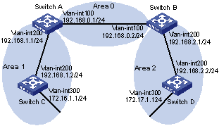
Figure 3-21 Network diagram for OSPF basic configuration
III. Configuration procedure
1) Configure IP addresses for interfaces (omitted)
2) Configure OSPF basic functions
# Configure Switch A.
<SwitchA> system-view
[SwitchA] ospf
[SwitchA-ospf-1] area 0
[SwitchA-ospf-1-area-0.0.0.0] network 192.168.0.0 0.0.0.255
[SwitchA-ospf-1-area-0.0.0.0] quit
[SwitchA-ospf-1] area 1
[SwitchA-ospf-1-area-0.0.0.1] network 192.168.1.0 0.0.0.255
[SwitchA-ospf-1-area-0.0.0.1] quit
[SwitchA-ospf-1] quit
# Configure Switch B.
<SwitchB> system-view
[SwitchB] ospf
[SwitchB-ospf-1] area 0
[SwitchB-ospf-1-area-0.0.0.0] network 192.168.0.0 0.0.0.255
[SwitchB-ospf-1-area-0.0.0.0] quit
[SwitchB-ospf-1] area 2
[SwitchB-ospf-1-area-0.0.0.2] network 192.168.2.0 0.0.0.255
[SwitchB-ospf-1-area-0.0.0.2] quit
[SwitchB-ospf-1] quit
# Configure Switch C
<SwitchC> system-view
[SwitchC] ospf
[SwitchC-ospf-1] area 1
[SwitchC-ospf-1-area-0.0.0.1] network 192.168.1.0 0.0.0.255
[SwitchC-ospf-1-area-0.0.0.1] network 172.16.1.0 0.0.0.255
[SwitchC-ospf-1-area-0.0.0.1] quit
[SwitchC-ospf-1] quit
# Configure Switch D
<SwitchD> system-view
[SwitchD] ospf
[SwitchD-ospf-1] area 2
[SwitchD-ospf-1-area-0.0.0.2] network 192.168.2.0 0.0.0.255
[SwitchD-ospf-1-area-0.0.0.2] network 172.17.1.0 0.0.0.255
[SwitchD-ospf-1-area-0.0.0.2] quit
[SwitchD-ospf-1] quit
3) Verify the configuration
# Display information about neighbors on Switch A.
[SwitchA] display ospf peer
OSPF Process 1 with Router ID 192.168.0.1
Neighbors
Area 0.0.0.0 interface 192.168.0.1(Vlan-interface 100)'s neighbors
Router ID: 192.168.0.2 Address: 192.168.0.2 GR State: Normal
State: Full Mode:Nbr is Master Priority: 1
DR: 192.168.0.2 BDR: 192.168.0.1 MTU: 0
Dead timer due in 36 sec
Neighbor is up for 00:15:04
Authentication Sequence: [ 0 ]
Neighbors
Area 0.0.0.1 interface 192.168.1.1(Vlan-interface 200)'s neighbors
Router ID: 172.16.1.1 Address: 192.168.1.2 GR State: Normal
State: Full Mode:Nbr is Slave Priority: 1
DR: 192.168.0.1 BDR: 172.16.1.1 MTU: 0
Dead timer due in 39 sec
Neighbor is up for 00:07:32
Authentication Sequence: [ 0 ]
# Display OSPF routing information on Switch A.
[SwitchA] display ospf routing
OSPF Process 1 with Router ID 192.168.0.1
Routing Tables
Routing for Network
Destination Cost Type NextHop AdvRouter Area
172.16.1.0/24 1563 Stub 192.168.1.2 172.16.1.1 0.0.0.1
172.17.1.0/24 3125 Inter-area 192.168.0.2 192.168.2.1 0.0.0.0
192.168.1.0/24 1562 Stub 192.168.1.1 192.168.0.1 0.0.0.1
192.168.2.0/24 3124 Inter-area 192.168.0.2 192.168.2.1 0.0.0.0
192.168.0.0/24 1562 Stub 192.168.0.1 192.168.0.1 0.0.0.0
Total Nets: 5
Intra Area: 3 Inter Area: 2 ASE: 0 NSSA: 0
# Display the Link State Database on Switch A.
[SwitchA] display ospf lsdb
OSPF Process 1 with Router ID 192.168.0.1
Link State Data Base
Area: 0.0.0.0
Type LinkState ID AdvRouter Age Len Sequence Metric
Router 192.168.2.1 192.168.2.1 874 48 80000006 1562
Router 192.168.0.1 192.168.0.1 976 48 80000005 1562
Sum-Net 192.168.1.0 192.168.0.1 630 28 80000001 1562
Sum-Net 172.17.1.0 192.168.2.1 411 28 80000001 1563
Sum-Net 192.168.2.0 192.168.2.1 429 28 80000001 1562
Sum-Net 172.16.1.0 192.168.0.1 565 28 80000001 1563
Area: 0.0.0.1
Type LinkState ID AdvRouter Age Len Sequence Metric
Router 192.168.1.2 192.168.1.2 964 48 80000003 1562
Router 192.168.0.1 192.168.0.1 590 48 80000002 1562
Router 172.16.1.1 172.16.1.1 526 60 80000005 1562
Sum-Net 172.17.1.0 192.168.0.1 410 28 80000001 3125
Sum-Net 192.168.2.0 192.168.0.1 428 28 80000001 3124
Sum-Net 192.168.0.0 192.168.0.1 630 28 80000001 1562
# Display OSPF routing information on Switch D.
[SwitchD] display ospf routing
OSPF Process 1 with Router ID 192.168.2.2
Routing Tables
Routing for Network
Destination Cost Type NextHop AdvRouter Area
172.16.1.0/24 4687 Inter-area 192.168.2.1 192.168.2.1 0.0.0.2
172.17.1.0/24 1 Stub 172.17.1.1 192.168.2.2 0.0.0.2
192.168.1.0/24 4686 Inter-area 192.168.2.1 192.168.2.1 0.0.0.2
192.168.2.0/24 1562 Stub 192.168.2.2 192.168.2.2 0.0.0.2
192.168.0.0/24 3124 Inter-area 192.168.2.1 192.168.2.1 0.0.0.2
Total Nets: 5
Intra Area: 2 Inter Area: 3 ASE: 0 NSSA: 0
# Ping the IP address 172.16.1.1 to check connectivity.
[SwitchD] ping 172.16.1.1
PING 172.16.1.1: 56 data bytes, press CTRL_C to break
Reply from 172.16.1.1: bytes=56 Sequence=1 ttl=253 time=62 ms
Reply from 172.16.1.1: bytes=56 Sequence=2 ttl=253 time=16 ms
Reply from 172.16.1.1: bytes=56 Sequence=3 ttl=253 time=62 ms
Reply from 172.16.1.1: bytes=56 Sequence=4 ttl=253 time=94 ms
Reply from 172.16.1.1: bytes=56 Sequence=5 ttl=253 time=63 ms
--- 172.16.1.1 ping statistics ---
5 packet(s) transmitted
5 packet(s) received
0.00% packet loss
round-trip min/avg/max = 16/59/94 ms
3.10.2 Configuring an OSPF Stub Area
I. Network requirements
The following figure shows an AS is split into three areas, where all switches run OSPF. Switch A and Switch B act as ABRs to forward routing information between areas. Switch D acts as the ASBR to redistribute routes (static routes).
It is required to configure Area 1 as a Stub area, reducing LSAs to this area without affecting route reachability.
II. Network diagram
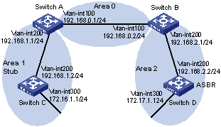
Figure 3-22 Network diagram for OSPF Stub area configuration
III. Configuration procedure
1) Configure IP addresses for interfaces (omitted).
2) Configure OSPF basic functions (refer to Configuring OSPF Basic Functions).
3) Configure Switch D to redistribute static routes.
[SwitchD] ip route-static 200.0.0.0 8 null 0
[SwitchD] ospf
[SwitchD-ospf-1] import-route static
[SwitchD-ospf-1] quit
# Display ABR/ASBR information on Switch C.
[SwitchC] display ospf abr-asbr
OSPF Process 1 with Router ID 172.16.1.1
Routing Table to ABR and ASBR
Type Destination Area Cost Nexthop RtType
Intra-area 192.168.0.1 0.0.0.1 1562 192.168.1.1 ABR
Inter-area 172.17.1.1 0.0.0.1 4686 192.168.1.1 ASBR
# Display OSPF routing table information on Switch C.
[SwitchC] display ospf routing
OSPF Process 1 with Router ID 172.16.1.1
Routing Tables
Routing for Network
Destination Cost Type NextHop AdvRouter Area
172.16.1.0/24 1 Stub 172.16.1.1 172.16.1.1 0.0.0.1
172.17.1.0/24 4687 Inter-area 192.168.1.1 192.168.0.1 0.0.0.1
192.168.1.0/24 1562 Stub 192.168.1.2 172.16.1.1 0.0.0.1
192.168.2.0/24 4686 Inter-area 192.168.1.1 192.168.0.1 0.0.0.1
192.168.0.0/24 3124 Inter-area 192.168.1.1 192.168.0.1 0.0.0.1
Routing for ASEs
Destination Cost Type Tag NextHop AdvRouter
200.0.0.0/8 10 Type2 1 192.168.1.1 172.17.1.1
Routing for NSSAs
Destination Cost Type Tag NextHop AdvRouter
Total Nets: 6
Intra Area: 2 Inter Area: 3 ASE: 1 NSSA: 0
& Note:
In the above output, since Switch C resides in a normal OSPF area, its routing table contains an external route.
4) Configure Area 1 as a Stub area.
# Configure Switch A.
[SwitchA] ospf
[SwitchA-ospf-1] area 1
[SwitchA-ospf-1-area-0.0.0.1] stub
[SwitchA-ospf-1-area-0.0.0.1] quit
[SwitchA-ospf-1] quit
# Configure Switch C.
[SwitchC] ospf
[SwitchC-ospf-1] stub-router
[SwitchC-ospf-1] area 1
[SwitchC-ospf-1-area-0.0.0.1] stub
[SwitchC-ospf-1-area-0.0.0.1] quit
[SwitchC-ospf-1] quit
# Display OSPF routing information on Switch C
[SwitchC] display ospf routing
OSPF Process 1 with Router ID 172.16.1.1
Routing Tables
Routing for Network
Destination Cost Type NextHop AdvRouter Area
0.0.0.0/0 65536 Inter-area 192.168.1.1 192.168.0.1 0.0.0.1
172.16.1.0/24 1 Stub 172.16.1.1 172.16.1.1 0.0.0.1
172.17.1.0/24 68660 Inter-area 192.168.1.1 192.168.0.1 0.0.0.1
192.168.1.0/24 1562 Stub 192.168.1.2 172.16.1.1 0.0.0.1
192.168.2.0/24 68659 Inter-area 192.168.1.1 192.168.0.1 0.0.0.1
192.168.0.0/24 67097 Inter-area 192.168.1.1 192.168.0.1 0.0.0.1
Total Nets: 6
Intra Area: 2 Inter Area: 4 ASE: 0 NSSA: 0
& Note:
When Switch C resides in the Stub area, a default route takes the place of the external route.
# Filter Type-3 LSAs out the stub area
[SwitchA] ospf
[SwitchA-ospf-1] area 1
[SwitchA-ospf-1-area-0.0.0.1] stub no-summary
[SwitchA-ospf-1-area-0.0.0.1] quit
# Display OSPF routing information on Switch C.
[SwitchC] display ospf routing
OSPF Process 1 with Router ID 172.16.1.1
Routing Tables
Routing for Network
Destination Cost Type NextHop AdvRouter Area
0.0.0.0/0 1563 Inter-area 192.168.1.1 192.168.0.1 0.0.0.1
172.16.1.0/24 1 Stub 172.16.1.1 172.16.1.1 0.0.0.1
192.168.1.0/24 1562 Stub 192.168.1.2 172.16.1.1 0.0.0.1
Total Nets: 3
Intra Area: 2 Inter Area: 1 ASE: 0 NSSA: 0
& Note:
After this configuration, routing entries on the stub router are further reduced, containing only one default external route.
3.10.3 Configuring an OSPF NSSA Area
I. Network requirements
The following figure shows an AS is split into three areas, where all switches run OSPF. Switch A and Switch B act as ABRs to forward routing information between areas. Switch D acts as the ASBR to redistribute routes (static routes).
It is required to configure Area 1 as an NSSA area, and configure Router C as the ASBR to redistribute static routes into the AS.
II. Network diagram
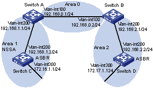
Figure 3-23 Network diagram for OSPF NSSA area configuration
III. Configuration procedure
1) Configure IP addresses for interfaces.
2) Configure OSPF basic functions (refer to Configuring OSPF Basic Functions ).
3) Configure Switch D to import external static routes (refer to Configuring an OSPF Stub Area)
4) Configure Area 1 as an NSSA area.
# Configure Switch A.
[SwitchA] ospf
[SwitchA-ospf-1] area 1
[SwitchA-ospf-1-area-0.0.0.1] nssa default-route-advertise no-summary
[SwitchA-ospf-1-area-0.0.0.0] quit
[SwitchA-ospf-1] quit
# Configure Switch C.
[SwitchC] ospf
[SwitchC-ospf-1] area 1
[SwitchC-ospf-1-area-0.0.0.1] nssa
[SwitchC-ospf-1-area-0.0.0.1] quit
[SwitchC-ospf-1] quit
& Note:
It is recommended to configure the nssa command with the keyword default-route-advertise no-summary on Switch A (an ABR) to reduce the routing table size on NSSA routers. On other NSSA routers, using the nssa command is ok.
# Display OSPF routing information on Switch C.
[SwitchC] display ospf routing
OSPF Process 1 with Router ID 172.16.1.1
Routing Tables
Routing for Network
Destination Cost Type NextHop AdvRouter Area
0.0.0.0/0 1563 Inter-area 192.168.1.1 192.168.0.1 0.0.0.1
172.16.1.0/24 1 Stub 172.16.1.1 172.16.1.1 0.0.0.1
192.168.1.0/24 1562 Stub 192.168.1.2 172.16.1.1 0.0.0.1
Total Nets: 3
Intra Area: 2 Inter Area: 1 ASE: 0 NSSA: 0
5) Configure Switch C to redistribute static routes.
[SwitchC] ip route-static 100.0.0.0 8 null 0
[SwitchC] ospf
[SwitchC-ospf-1] import-route static
[SwitchC-ospf-1] quit
# Display OSPF routing information on Switch D.[SwitchD-ospf-1] display ospf routing
OSPF Process 1 with Router ID 172.17.1.1
Routing Tables
Routing for Network
Destination Cost Type NextHop AdvRouter Area
172.16.1.0/24 4687 Inter-area 192.168.2.1 192.168.0.2 0.0.0.2
172.17.1.0/24 1 Stub 172.17.1.1 172.17.1.1 0.0.0.2
192.168.1.0/24 4686 Inter-area 192.168.2.1 192.168.0.2 0.0.0.2
192.168.2.0/24 1562 Stub 192.168.2.2 172.17.1.1 0.0.0.2
192.168.0.0/24 3124 Inter-area 192.168.2.1 192.168.0.2 0.0.0.2
Routing for ASEs
Destination Cost Type Tag NextHop AdvRouter
100.0.0.0/8 10 Type2 1 192.168.2.1 192.168.0.1
Routing for NSSAs
Destination Cost Type Tag NextHop AdvRouter
Total Nets: 6
Intra Area: 2 Inter Area: 3 ASE: 1 NSSA: 0
& Note:
You can see on Switch D an external route imported from the NSSA area.
3.10.4 Configuring OSPF DR Election
I. Network requirements
l In the following figure, OSPF Switches A, B, C and D reside on the same network segment.
l It is required to configure Switch A as the DR, and configure Switch C as the BDR.
II. Network diagram
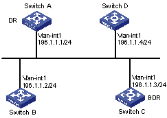
Figure 3-24 Network diagram for OSPF DR election configuration
III. Configuration procedure
1) Configure IP addresses for interfaces (omitted)
2) Configure OSPF basic functions
# Configure Switch A.
<SwitchA> system-view
[Switch A] router id 1.1.1.1
[Switch A] ospf
[Switch A-ospf-1] area 0
[Switch A-ospf-1-area-0.0.0.0] network 196.1.1.0 0.0.0.255
[SwitchA-ospf-1-area-0.0.0.0] quit
[SwitchA-ospf-1] quit
# Configure Switch B.
<SwitchB> system-view
[SwitchB] router id 2.2.2.2
[SwitchB] ospf
[SwitchB-ospf-1] area 0
[SwitchB-ospf-1-area-0.0.0.0] network 196.1.1.0 0.0.0.255
[SwitchB-ospf-1-area-0.0.0.0] quit
[SwitchB-ospf-1] quit
# Configure Switch C.
<SwitchC> system-view
[SwitchC] router id 3.3.3.3
[SwitchC] ospf
[SwitchC-ospf-1] area 0
[SwitchC-ospf-1-area-0.0.0.0] network 196.1.1.0 0.0.0.255
[SwitchC-ospf-1-area-0.0.0.0] quit
[SwitchC-ospf-1] quit
# Configure Switch D.
<SwitchD> system-view
[SwitchD] router id 4.4.4.4
[SwitchD] ospf
[SwitchD-ospf-1] area 0
[SwitchD-ospf-1-area-0.0.0.0] network 196.1.1.0 0.0.0.255
[SwitchD-ospf-1-area-0.0.0.0] quit
[SwitchD-ospf-1] quit
# Display OSPF neighbor information on Switch A.
[SwitchA] display ospf peer
OSPF Process 1 with Router ID 1.1.1.1
Neighbors
Area 0.0.0.0 interface 192.168.1.1(Vlan-interface1)'s neighbors
Router ID: 2.2.2.2 Address: 192.168.1.2 GR State: Normal
State: 2-Way Mode: None Priority: 1
DR: 192.168.1.4 BDR: 192.168.1.3 MTU: 0
Dead timer due in 38 sec
Neighbor is up for 00:01:31
Authentication Sequence: [ 0 ]
Router ID: 3.3.3.3 Address: 192.168.1.3 GR State: Normal
State: Full Mode: Nbr is Master Priority: 1
DR: 192.168.1.4 BDR: 192.168.1.3 MTU: 0
Dead timer due in 31 sec
Neighbor is up for 00:01:28
Authentication Sequence: [ 0 ]
Router ID: 4.4.4.4 Address: 192.168.1.4 GR State: Normal
State: Full Mode: Nbr is Master Priority: 1
DR: 192.168.1.4 BDR: 192.168.1.3 MTU: 0
Dead timer due in 31 sec
Neighbor is up for 00:01:28
Authentication Sequence: [ 0 ]
Switch D becomes the DR, and Switch C is the BDR.
3) Configure router priorities on interfaces
# Configure Switch A.
[SwitchA] interface vlan-interface 1
[RouterA-Vlan-interface1] ospf dr-priority 100
[RouterA-Vlan-interface1] quit
# Configure Switch B.
[SwitchB] interface vlan-interface 1
[SwitchB-Vlan-interface1] ospf dr-priority 0
[SwitchB-Vlan-interface1] quit
# Configure Switch C.
[SwitchC] interface vlan-interface 1
[SwitchC-Vlan-interface1] ospf dr-priority 2
[SwitchC-Vlan-interface] quit
# Display neighbor information on Switch D.
[SwitchD] display ospf peer
OSPF Process 1 with Router ID 4.4.4.4
Neighbors
Area 0.0.0.0 interface 192.168.1.4(Vlan-interface1)'s neighbors
Router ID: 1.1.1.1 Address: 192.168.1.1 GR State: Normal
State: Full Mode:Nbr is Slave Priority: 100
DR: 192.168.1.4 BDR: 192.168.1.3 MTU: 0
Dead timer due in 31 sec
Neighbor is up for 00:11:17
Authentication Sequence: [ 0 ]
Router ID: 2.2.2.2 Address: 192.168.1.2 GR State: Normal
State: Full Mode:Nbr is Slave Priority: 0
DR: 192.168.1.4 BDR: 192.168.1.3 MTU: 0
Dead timer due in 35 sec
Neighbor is up for 00:11:19
Authentication Sequence: [ 0 ]
Router ID: 3.3.3.3 Address: 192.168.1.3 GR State: Normal
State: Full Mode:Nbr is Slave Priority: 2
DR: 192.168.1.4 BDR: 192.168.1.3 MTU: 0
Dead timer due in 33 sec
Neighbor is up for 00:11:15
Authentication Sequence: [ 0 ]
The DR and BDR have no change.
& Note:
In the above output, you can find the priority configuration does not take effect immediately.
4) Restart OSPF process (omitted)
# Display neighbor information on Switch D.
[SwitchD] display ospf peer
OSPF Process 1 with Router ID 4.4.4.4
Neighbors
Area 0.0.0.0 interface 192.168.1.4(Vlan-interface1)'s neighbors
Router ID: 1.1.1.1 Address: 192.168.1.1 GR State: Normal
State: Full Mode: Nbr is Slave Priority: 100
DR: 192.168.1.1 BDR: 192.168.1.3 MTU: 0
Dead timer due in 39 sec
Neighbor is up for 00:01:40
Authentication Sequence: [ 0 ]
Router ID: 2.2.2.2 Address: 192.168.1.2 GR State: Normal
State: 2-Way Mode: None Priority: 0
DR: 192.168.1.1 BDR: 192.168.1.3 MTU: 0
Dead timer due in 35 sec
Neighbor is up for 00:01:44
Authentication Sequence: [ 0 ]
Router ID: 3.3.3.3 Address: 192.168.1.3 GR State: Normal
State: Full Mode: Nbr is Slave Priority: 2
DR: 192.168.1.1 BDR: 192.168.1.3 MTU: 0
Dead timer due in 39 sec
Neighbor is up for 00:01:41
Authentication Sequence: [ 0 ]
Switch A becomes the DR, and Switch C is the BDR.
& Note:
If the neighbor state is full, it means Switch D has established the adjacency with the neighbor. If the neighbor state is 2-way, it means the two switches are neither the DR nor the BDR, and they do not exchange LSAs.
# Display OSPF interface information.
[SwitchA] display ospf interface
OSPF Process 1 with Router ID 1.1.1.1
Interfaces
Area: 0.0.0.0
IP Address Type State Cost Pri DR BDR
192.168.1.1 Broadcast DR 1 100 192.168.1.1 192.168.1.3
[SwitchB] display ospf interface
OSPF Process 1 with Router ID 2.2.2.2
Interfaces
Area: 0.0.0.0
IP Address Type State Cost Pri DR BDR
192.168.1.2 Broadcast DROther 1 0 192.168.1.1 192.168.1.3
& Note:
The interface state DROther means the interface is not the DR/BDR.
3.10.5 Configuring OSPF Virtual Links
I. Network requirements
In the following figure, Area 2 has no direct connection to Area 0, and Area 1 acts as the Transit Area to connect Area 2 to Area 0 via a configured virtual link between Switch B and Switch C.
After configuration, Switch A can learn routes to Area 2.
II. Network diagram
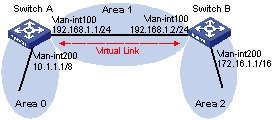
Figure 3-25 Network diagram for OSPF virtual link configuration
III. Configuration procedure
1) Configure IP addresses for interfaces (omitted)
2) Configure OSPF basic functions
# Configure Switch A.
<SwitchA> system-view
[SwitchA] ospf 1 router-id 1.1.1.1
[SwitchA-ospf-1] area 0
[SwitchA-ospf-1-area-0.0.0.0] network 10.0.0.0 0.255.255.255
[SwitchA-ospf-1-area-0.0.0.0] quit
[SwitchA-ospf-1] area 1
[SwitchA-ospf-1-area-0.0.0.1] network 192.168.1.0 0.0.0.255
[SwitchA-ospf-1-area-0.0.0.1] quit
# Configure Switch B.
<SwitchB> system-view
[SwitchB] ospf 1 router-id 2.2.2.2
[SwitchB-ospf-1] area 1
[SwitchB-ospf-1-area-0.0.0.1] network 192.168.1.0 0.0.0.255
[SwitchB-ospf-1-area-0.0.0.1] quit
[SwitchB-ospf-1] area 2
[SwitchB–ospf-1-area-0.0.0.2] network 172.16.0.0 0.0.255.255
[SwitchB–ospf-1-area-0.0.0.2] quit
# Display OSPF routing information on Switch A.
[SwitchA] display ospf routing
OSPF Process 1 with Router ID 1.1.1.1
Routing Tables
Routing for Network
Destination Cost Type NextHop AdvRouter Area
10.0.0.0/8 1 Stub 10.1.1.1 1.1.1.1 0.0.0.0
192.168.1.0/24 1562 Stub 192.168.1.1 1.1.1.1 0.0.0.1
Total Nets: 2
Intra Area: 2 Inter Area: 0 ASE: 0 NSSA: 0
& Note:
Since Area 2 has no direct connection to Area 0, the OSPF routing table of Router A has no route to Area 2.
3) Configure a virtual link
# Configure Switch A.
[SwitchA] ospf
[SwitchA-ospf-1] area 1
[SwitchA-ospf-1-area-0.0.0.1] vlink-peer 2.2.2.2
[SwitchA-ospf-1-area-0.0.0.1] quit
[SwitchA-ospf-1] quit
# Configure Switch B.
[SwitchB] ospf 1
[SwitchB-ospf-1] area 1
[SwitchB-ospf-1-area-0.0.0.1] vlink-peer 1.1.1.1
[SwitchB-ospf-1-area-0.0.0.1] quit
# Display OSPF routing information on Switch A.
[SwitchA] display ospf routing
OSPF Process 1 with Router ID 1.1.1.1
Routing Tables
Routing for Network
Destination Cost Type NextHop AdvRouter Area
172.16.1.1/16 1563 Inter 192.168.1.2 2.2.2.2 0.0.0.0
10.0.0.0/8 1 Stub 10.1.1.1 1.1.1.1 0.0.0.0
192.168.1.0/24 1562 Stub 192.168.1.1 1.1.1.1 0.0.0.1
Total Nets: 3
Intra Area: 2 Inter Area: 1 ASE: 0 NSSA: 0
Switch A has learned the route 172.16.1.1/16 to Area2.
3.10.6 OSPF Graceful Restart Configuration Example
I. Network requirements
l Switch A, Switch B and Switch C that belong to the same autonomous system and the same OSPF routing domain are GR capable.
l Switch A acts as the non IETF standard GR Restarter whereas Switch B and Switch C are the GR Helpers and remain OOB synchronized with Switch A through the GR mechanism.
II. Network diagram
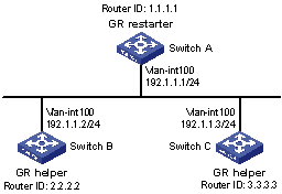
Figure 3-26 Network diagram for OSPF-based GR configuration
III. Configuration procedure
1) Configure Switch A
<SwitchA> system-view
[SwitchA] interface vlan-interface 100
[SwitchA-Vlan-interface100] ip address 192.1.1.1 255.255.255.0
[SwitchA-Vlan-interface100] quit
[SwitchA] router id 1.1.1.1
[SwitchA] ospf 100
[SwitchA-ospf-100] enable link-local-signaling
[SwitchA-ospf-100] enable out-of-band-resynchronization
[RouterA-ospf-100] graceful-restart
[SwitchA-ospf-100] area 0
[SwitchA-ospf-100-area-0.0.0.0] network 192.1.1.0 0.0.0.255
[SwitchA-ospf-100-area-0.0.0.0] return
2) Configure Switch B
<SwitchB> system-view
[SwitchB] acl number 2000
[SwitchB-acl-basic-2000] rule 10 permit source 192.1.1.1 0.0.0.0
[SwitchB-acl-basic-2000] quit
[SwitchB] interface vlan-interface 100
[SwitchB-Vlan-interface100] ip address 192.1.1.2 255.255.255.0
[SwitchB-Vlan-interface100] ospf dr-priority 0
[SwitchB-Vlan-interface100] quit
[SwitchB] router id 2.2.2.2
[SwitchB] ospf 100
[SwitchB-ospf-100] enable link-local-signaling
[SwitchB-ospf-100] enable out-of-band-resynchronization
[SwitchB-ospf-100] graceful-restart help 2000
[SwitchB-ospf-100] area 0
[SwitchB-ospf-100-area-0.0.0.0] network 192.1.1.0 0.0.0.255
[SwitchB-ospf-100-area-0.0.0.0] quit
3) Configure Switch C
<SwitchC> system-view
[SwitchC] interface vlan-interface 100
[SwitchC-Vlan-interface100] ip address 192.1.1.3 255.255.255.0
[SwitchC-Vlan-interface100] ospf dr-priority 2
[SwitchC-Vlan-interface100] quit
[SwitchC] router id 3.3.3.3
[SwitchC] ospf 100
[SwitchC-ospf-100] enable link-local-signaling
[SwitchC-ospf-100] enable out-of-band-resynchronization
[SwitchC-ospf-100] area 0
[SwitchC-ospf-100-area-0.0.0.0] network 192.1.1.0 0.0.0.255
[SwitchC-ospf-100-area-0.0.0.0] quit
4) Verify the configuration
# After the configurations on Switch A, Switch B and Switch C are completed and the switches are running steadily, perform OSPF GR on Switch A.
<SwitchA> reset ospf 100 process graceful-restart
3.11 Troubleshooting OSPF Configuration
3.11.1 No OSPF Neighbor Relationship Established
I. Symptom
No OSPF neighbor relationship can be established.
II. Analysis
If the physical link and lower layer protocols work well, check OSPF parameters configured on interfaces. Two neighbors must have the same parameters, such as the area ID, network segment and mask (a P2P or virtual link may have different network segments and masks), network type. If the network type is broadcast or NBMA, at least one interface must have a router priority higher than 0.
III. Processing steps
1) Display OSPF neighbor information using the display ospf peer command.
2) Display OSPF interface information using the display ospf interface command.
3) Ping the neighbor router’s IP address to check connectivity.
4) Check OSPF timers. The dead interval on an interface must be at least four times the hello interval.
5) On an NBMA network, using the peer ip-address command to specify the neighbor manually is required.
6) On an NBMA or a broadcast network, at least one connected interface must have a router priority higher than 0.
3.11.2 Incorrect Routing Information
I. Symptom
OSPF cannot find routes to other areas.
II. Analysis
The backbone area must maintain connectivity to all other areas. If a router connects to more than one area, at least one area must be connected to the backbone. The backbone cannot be configured as a Stub area.
In a Stub area, all routers cannot receive external routes, and all interfaces connected to the Stub area must belong to the Stub area.
III. Solution
1) Use the display ospf peer command to display neighbors.
2) Use the display ospf interface command to display OSPF interface information.
3) Use the display ospf lsdb command to display the Link State Database to check its integrity.
4) Display information about area configuration using the display current-configuration configuration ospf command. If more than two areas are configured, at least one area is connected to the backbone.
5) In a Stub area, all routers attached are configured with the stub command. In an NSSA area, all interface connected to which are configured with the nssa command.
6) If a virtual link is configured, use the display ospf vlink command to check the state of the virtual link.
Chapter 4 IS-IS Configuration
When configuring IS-IS, go to these sections for information you are interested in:
l IS-IS Configuration Task List
l Configuring IS-IS Basic Functions
l Configuring IS-IS Routing Information Control
l Tuning and Optimizing IS-IS Network
l Displaying and Maintaining IS-IS
& Note:
l The term “router” in this document refers to a router in a generic sense or an Ethernet switch running routing protocols.
l The value ranges of the parameters of the commands in this manual use the ranges assuming the switch operate in the default mode. When the switch operates in the IPv4/IPv6 dual-stack or the MCE mode, the value ranges of some parameters may vary. For the operating modes of the switch, refer to the parts discussing IPv6 configuration or MCE
4.1 IS-IS Overview
Intermediate System-to-Intermediate System (IS-IS) is a dynamic routing protocol designed by the International Organization for Standardization (ISO) to operate on the connectionless network protocol (CLNP).
The IS-IS routing protocol has been modified and extended in RFC 1195 by the International Engineer Task Force (IETF) for application in both TCP/IP and OSI reference models, and the new one is called Integrated IS-IS or Dual IS-IS.
IS-IS is an interior gateway protocol (IGP) used within an Autonomous System. It adopts the Shortest Path First (SPF) algorithm for route calculation.
4.1.1 Basic Concepts
I. IS-IS terminology
l Intermediate system (IS). An IS, similar to a router in TCP/IP, is the basic unit in IS-IS protocol to generate and propagate routing information. In the following text, an IS is a router.
l End system (ES). An ES refers to a host system in TCP/IP. ISO defines the ES-IS protocol for communication between an ES and an IS, therefore an ES does not participate in the IS-IS process.
l Routing domain (RD). A group of ISs exchange routing information with the same routing protocol in a routing domain.
l Area. An area is a division unit in a routing domain. The IS-IS protocol allows a routing domain to be divided into multiple areas.
l Link State Database (LSDB). All link states in the network forms the LSDB. There is at least one LSDB in each IS. The IS uses SPF algorithm and LSDB to generate its own routes.
l Link State Protocol Data Unit (LSPDU) or Link State Packet (LSP). Each IS can generate a LSP which contains all the link state information of the IS.
l Network Protocol Data Unit (NPDU). An NPDU is a network layer protocol packet in ISO, which is equivalent to an IP packet in TCP/IP.
l Designated IS. On a broadcast network, the designated router is also known as the designated IS or a pseudonode.
l Network service access point (NSAP). The NSAP is the ISO network layer address. It identifies an abstract network service access point and describes the network address in the ISO reference model.
II. IS-IS address structure
1) NSAP
As shown in Figure 4-1, the NSAP address consists of the Initial Domain Part (IDP) and the Domain Specific Part (DSP). The IDP is equal to the network ID of the IP address, and the DSP is equal to the subnet and host IDs.
The IDP, defined by ISO, includes the Authority and Format Identifier (AFI) and the Initial Domain Identifier (IDI).
The DSP includes the High Order DSP (HODSP), the System ID and SEL, where the HODSP identifies the area, the System ID identifies the host, and the SEL indicates the type of service.
The length of IDP and DSP is variable. The length of the NSAP address varies from 8 bytes to 20 bytes.
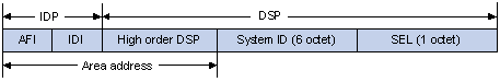
Figure 4-1 NSAP address structure
2) Area address
The area address is composed of the IDP and the HODSP of the DSP, which identify the area and the routing domain. Different routing domains cannot have the same area address.
Generally, a router only needs one area address, and all nodes in the same routing domain must share the same area address. However, a router can have three area addresses at most to support smooth area merging, partitioning and switching.
3) System ID
The system ID identifies the host or router uniquely. It has a fixed length of 48 bits.
The system ID is used in cooperation with the Router ID in practical. For example, a router uses the IP address 168.10.1.1 of the Loopback 0 as the Router ID, the system ID in IS-IS can be obtained in the following way:
l Extend each decimal number of the IP address to 3 digits by adding 0s from the left, like 168.010.001.001;
l Divide the extended IP address into 3 sections with 4 digits in each section to get the System ID 1680.1000.1001.
There are other methods to define a system ID. Just make sure it can uniquely identify a host or router.
4) SEL
The NSAP Selector (SEL), sometimes present in N-SEL, is similar with the protocol identifier in IP. Different transport layer protocols use different SELs. All SELs in IP are 00.
5) Routing method
Since the area is explicitly defined in the address structure, the Level-1 router can easily recognize the packets sent out of the area. These packets are forwarded to the Level-2 router.
The Level-1 router makes routing decisions based on the system ID. If the destination is not in the area, the packet is forwarded to the nearest Level-1-2 router.
The Level-2 router routes packets across areas according to the area address.
III. NET
A Network Entity Title (NET) is an NSAP with SEL being 0. It indicates the network layer information of the IS itself, with no transport layer information. Therefore, the length of NET is equal to NSAP, in the range 8 bytes to 20 bytes.
Generally, a router only needs one NET, but it can have three NETs at most for smooth area merging and partitioning. When you configure multiple NETs, make sure their system IDs are the same.
For example, a NET is ab.cdef.1234.5678.9abc.00, where,
Area = ab.cdef, System ID = 1234.5678.9abc, and SEL = 00.
4.1.2 IS-IS Area
I. Two-level hierarchy
IS-IS uses two-level hierarchy in the routing domain to support large scale routing networks. A large routing domain is generally divided into multiple Areas. The Level-1 router is in charge of forwarding routes within an area, and the Level-2 router is in charge of forwarding routes between areas.
II. Level-1 and Level-2
1) Level-1 router
The Level-1 router only establishes the neighbor relationship with Level-1 and Level-1-2 routers in the same area. The LSDB maintained by the Level-1 router contains the local area routing information. It directs the packets out of the area to the nearest Level-1-2 router.
2) Level-2 router
The Level-2 router establishes the neighbor relationships with the Level-2 and Level-1-2 routers in the same or in different areas. It maintains a Level-2 LSDB which contains inter area routing information. All the Level-2 and Level-1-2 routers must be contiguous to form the backbone in a routing domain. Only Level-2 routers can directly communicate with routers outside the routing domain.
3) Level-1-2 router
A router with both Level-1 and Level-2 router functions is called a Level-1-2 router. It can establish the Level-1 neighbor relationship with the Level-1 and Level-1-2 routers in the same area, or establish Level-2 neighbor relationship with the Level-2 and Level-1-2 routers in different areas. A Level-1 router must be connected to other areas via a Level-1-2 router. The Level-1-2 router maintains two LSDBs, where the Level-1 LSDB is for routing within the area, and the Level-2 LSDB is for routing between areas.
& Note:
l The Level-1 routers in different areas can not establish the neighbor relationship.
l The neighbor relationship establishment of Level-2 routers has nothing to do with area.
Figure 4-2 shows a network topology running the IS-IS protocol. Area 1 is a set of Level-2 routers, called backbone network. The other four areas are non-backbone networks connected to the backbone through Level-1-2 routers.
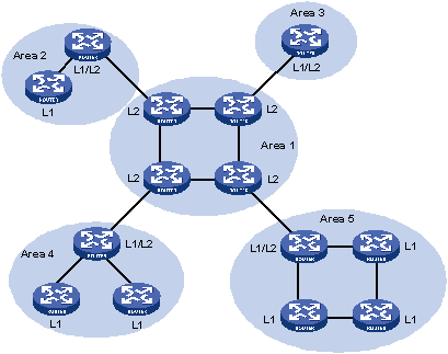
Figure 4-3 shows another network topology running the IS-IS protocol. The Level-1-2 routers connect the Level-1 and Level-2 routers, and also form the IS-IS backbone together with the Level-2 routers. There is no area defined as the backbone in this topology. The backbone is composed of all contiguous Level-2 and Level-1-2 routers which can reside in different areas.
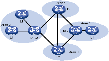
& Note:
The IS-IS backbone does not need to be a specific Area.
Both the IS-IS Level-1 and Level-2 routers use the SPF algorithm to generate the Shortest Path Tree (SPT).
III. Interface routing hierarchy type
You can configure the routing type for each interface. For a Level-1-2 router, one interface may establish Level-1 adjacency with a router, and another one may establish Level-2 adjacency with another router. You can limit the adjacency type by configuring the routing hierarchy on the interface. For example, the level-1 interface can only establish Level-1 adjacency, while the level-2 interface can only establish Level-2 adjacency.
By having this function, you can prevent the Level-1 hello packets from propagating to the Level-2 backbone through the Lever-1-2 router. This can result in bandwidth saving.
IV. Route leaking
An IS-IS routing domain is comprised of only one Level-2 area and multiple Level-1 areas. A Level-1 area is connected with the Level-2 area rather than other Level-1 areas.
The routing information of the Level-1 area is sent to the Level-2 area through the Level-1-2 router. Therefore, the Level-2 router knows the routing information of the entire IS-IS routing domain but does not share the information with the Level-1 area by default.
Since the Level-1 router simply sends the routing information for destinations outside the area to the nearest Level-1-2 router, this may cause a problem that the best path cannot be selected.
To solve this problem, route leaking was introduced. The Level-2 router can advertise the Level-2 routing information to a specified Level-1 area. By having the routing information of other areas, the Level-1 router can make a better routing choice for the packets destined outside the area.
4.1.3 IS-IS Network Type
I. Network type
IS-IS supports two network types:
l Broadcast network, such as Ethernet, Token-Ring.
l Point-to-point network, such as PPP, HDLC.
& Note:
For the Non-Broadcast Multi-Access (NBMA) network, such as ATM, you need to configure point-to-point or broadcast network on its configured subinterfaces. IS-IS does not run on Point to Multipoint (P2MP) links.
II. DIS and pseudonodes
On an IS-IS broadcast network, a router has to be selected as the Designated Intermediate System (DIS).
The Level-1 and Level-2 DISs are selected respectively. You can assign different priorities for different level DIS selections. The higher a router’s priority is, the more likelihood the router becomes the DIS. If there are multiple routers with the same highest DIS priority, the one with the highest SNPA (Subnetwork Point of Attachment) address (which is the MAC address on a broadcast network) will be selected. A router can be the DIS for different levels.
As shown in Figure 4-4, the same level routers on the same network segment can establish adjacencies. This is different from OSPF.
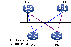
Figure 4-4 DIS in the IS-IS broadcast network
The DIS creates and updates pseudonodes as well as their LSP to describe all routers on the network.
The pseudonode emulates a virtual node on the broadcast network. It is not a real router. In IS-IS, it is identified by the system ID and one byte Circuit ID (a non zero value) of the DIS.
Using pseudonodes can reduce LSPs, the resources used by SPF and simplify the network topology.
& Note:
On IS-IS broadcast networks, all routers are adjacent with each other. The DIS is responsible for the synchronization of their LSDBs.
4.1.4 IS-IS PDU Format
I. PDU header format
The IS-IS packets are encapsulated into link layer frames. The Protocol Data Unit (PDU) consists of two parts, the headers and the variable length field, where the headers can be further divided into the common header and the specific header. The common headers are the same for all PDUs, while the specific headers vary by PDU type. The following figure shows the PDU format.
![]()
Figure 4-5 PDU format
II. Common header format
Figure 4-6 shows the common header format.
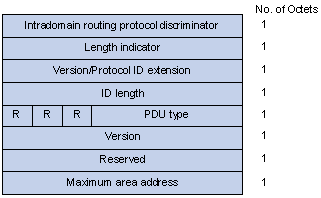
Figure 4-6 PDU common header format
l Intradomain Routing Protocol Discriminator: Set to 0x83.
l Length Indicator: The length of the PDU header, including both common and specific headers, present in bytes.
l Version/Protocol ID Extension: Set to 1(0x01).
l ID Length: The length of the NSAP address and NET ID.
l R(Reserved): Set to 0.
l PDU Type: For detail information, refer to Table 4-1.
l Version: Set to 1(0x01).
l Maximum Area Address: Maximum number of area addresses supported.
Table 4-1 PDU type
|
Type |
PDU Type |
Acronym |
|
15 |
Level-1 LAN IS-IS hello PDU |
L1 LAN IIH |
|
16 |
Level-2 LAN IS-IS hello PDU |
L2 LAN IIH |
|
17 |
Point-to-Point IS-IS hello PDU |
P2P IIH |
|
18 |
Level-1 Link State PDU |
L1 LSP |
|
20 |
Level-2 Link State PDU |
L2 LSP |
|
24 |
Level-1 Complete Sequence Numbers PDU |
L1 CSNP |
|
25 |
Level-2 Complete Sequence Numbers PDU |
L2 CSNP |
|
26 |
Level-1 Partial Sequence Numbers PDU |
L1 PSNP |
|
27 |
Level-2 Partial Sequence Numbers PDU |
L2 PSNP |
III. Hello
The hello packet is used by routers to establish and maintain the neighbor relationship. It is also called IS-to-IS hello PDU (IIH). For broadcast network, the Level-1 router uses the Level-1 LAN IIH; and the Level-2 router uses the Level-2 LAN IIH. The P2P IIH is used on point-to-point network.
Figure 4-7 illustrates the hello packet format in broadcast networks, where the blue fields are the common header.
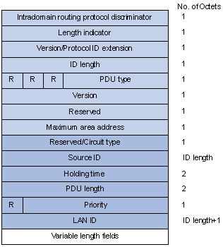
Figure 4-7 L1/L2 LAN IIH format
l Reserved/Circuit Type: The first 6 bits are reserved with value 0. The last 2 bits indicates router types: 00 means reserved, 01 indicates L1, 10 indicates L2, and 11 indicates L1/2.
l Source ID: The system ID of the router advertising the hello packet.
l Holding Time: If no hello packets are received from a neighbor within the holding time, the neighbor is considered dead.
l PDU Length: The total length of the PDU in bytes.
l Priority: DIS priority.
l LAN ID: Includes the system ID and one byte pseudonode ID.
Figure 4-8 shows the hello packet format on the point-to-point network.
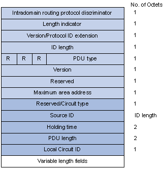
Figure 4-8 P2P IIH format
Instead of the priority and LAN ID fields in the LAN IIH, the P2P IIH has a Local Circuit ID field.
IV. LSP packet format
The Link State PDUs (LSP) carries link state information. There are two types: Level-1 LSP and Level-2 LSP. The Level-2 LSP is sent by the Level-2 router, and the Level-1 LSP is sent by the Level-1 router. The level-1-2 router can sent both types of the LSPs.
Two types of LSPs have the same format, as shown in Figure 4-9.
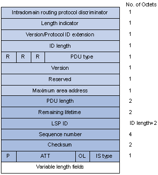
Figure 4-9 L1/L2 LSP format
l PDU Length: Total length of the PDU in bytes.
l Remaining Lifetime: LSP remaining lifetime in seconds.
l LSP ID: Consists of the system ID, the pseudonode ID (one byte) and the LSP fragment number (one byte).
l Sequence Number: LSP sequence number.
l Checksum: LSP checksum.
l P (Partition Repair): Only related with L2 LSP, indicates whether the router supports partition repair.
l ATT (Attachment): Generated by the L1/L1 router, only related with L1 LSP, indicates that the router generating the LSP is connected with multiple areas.
l OL (LSDB Overload): Indicates that the LSDB is not complete because the router is running out of system resources. In this condition, other routers will not send packets to the overloaded router, except packets destined to the networks directly connected to the router. For example, in Figure 4-10, Router A uses Router B to forward its packets to Router C in normal condition. Once other routers know the OL field on Router B is set to 1, Router A will send packets to Router C via Router D and Router E, but still send to Router B packets destined to the network directly connected to Router B.
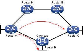
l IS Type: Type of the router generating the LSP.
V. SNP format
The Sequence Number PDU (SNP) confirms the latest received LSPs. It is similar to the Acknowledge packet, but more efficient.
SNP contains Complete SNP (CSNP) and Partial SNP (PSNP), which are further divided into Level-1 CSNP, Level-2 CSNP, Level-1 PSNP and Level-2 PSNP.
CSNP covers the summary of all LSPs in the LSDB to synchronize the LSDB between neighboring routers. On broadcast networks, CSNP is sent by the DIS periodically (10s by default). On point-to-point networks, CSNP is only sent during the first adjacency establishment.
The CSNP packet format is shown in Figure 4-11.
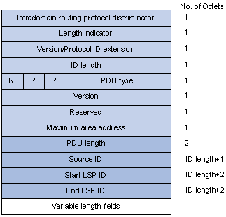
Figure 4-11 L1/L2 CSNP format
PSNP only contains the sequence numbers of one or multiple latest received LSPs. It can acknowledge multiple LSPs at one time. When LSDBs are not synchronized, a PSNP is used to request new LSPs from neighbors.
Figure 4-12 shows the PSNP packet format.
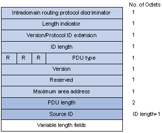
Figure 4-12 L1/L2 PSNP format
VI. CLV
The variable fields of PDU are composed of multiple Code-Length-Value (CLV) triplets. Figure 4-13 shows the CLV format.
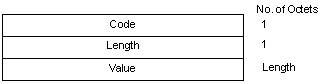
Figure 4-13 CLV format
Table 4-2 shows different PDUs contain different CLVs.
Table 4-2 CLV name and the corresponding PDU type
|
CLV Code |
Name |
PDU Type |
|
1 |
Area Addresses |
IIH, LSP |
|
2 |
IS Neighbors (LSP) |
LSP |
|
4 |
Partition Designated Level2 IS |
L2 LSP |
|
6 |
IS Neighbors (MAC Address) |
LAN IIH |
|
7 |
IS Neighbors (SNPA Address) |
LAN IIH |
|
8 |
Padding |
IIH |
|
9 |
LSP Entries |
SNP |
|
10 |
Authentication Information |
IIH, LSP, SNP |
|
128 |
IP Internal Reachability Information |
LSP |
|
129 |
Protocols Supported |
IIH, LSP |
|
130 |
IP External Reachability Information |
L2 LSP |
|
131 |
Inter-Domain Routing Protocol Information |
L2 LSP |
|
132 |
IP Interface Address |
IIH, LSP |
Code 1 to 10 of CLV are defined in ISO 10589 (code 3 and 5 are not shown in the table), and others are defined in RFC 1195.
4.1.5 IS-IS Features Supported
I. Multiple instances and processes
IS-IS supports multiple instances and processes. Multiple processes allow a designated IS-IS process to work in concert with a group of interfaces. This means that a router can run multiple IS-IS processes, and each process corresponds to a unique group of interfaces.
For routers supporting VPN, each IS-IS process is associated with a designated VPN instance. Thus, the VPN instance is also associated with interfaces corresponding to the process.
II. IS-IS Graceful Restart
& Note:
For detailed GR information, refer to BFD-GR Configuration.
After an IS-IS GR Restarter restarts IS-IS, it needs to complete the following two tasks to synchronize the LSDB with its neighbors.
l To obtain effective IS-IS neighbor information without changing adjacencies.
l To obtain the LSDB contents.
After the restart, the GR Restarter will send an OSPF GR signal to its neighbors to keep the adjacencies. After receiving the responses from neighbors, the GR Restarter can restore the neighbor table.
After reestablishing a neighbor relationship, the GR Restarter will synchronize the LSDB and exchange routing information with all adjacent GR capable neighbors. After that, the GR Restarter will update its own routing table and forwarding table based on the new routing information and remove the stale routes. In this way, the IS-IS routing convergence is complete.
III. Management tag
Management tag carries the management information of the IP address prefixes and BGP community attribute. It controls the redistribution from other routing protocols.
IV. LSP fragment extension
IS-IS advertises link state information by flooding LSPs. One LSP carries limited amount of link state information; therefore, IS-IS fragments LSPs. Each LSP fragment is uniquely identified by a combination of the System ID, Pseudonode ID (0 for a common LSP or non-zero for a Pseudonode LSP), and LSP Number (LSP fragment number) of the node or pseudo node that generated the LSP. The 1-byte LSP Number field, allowing a maximum of only 256 fragments to be generated by an IS-IS router, limits the amount of link information that the IS-IS router can advertise.
The LSP fragment extension feature allows an IS-IS router to generate more LSP fragments. Up to 50 additional virtual systems can be configured on the router, with each virtual system capable of generating 256 LSP fragments, to enable the IS-IS router to generate up to 13056 LSP fragments.
1) Terms
l Originating System
It is the router actually running IS-IS. After LSP fragment extension is enabled, additional virtual systems can be configured for the router. Originating system is the actual IS-IS process that originally runs.
l System ID
The system ID of the originating system.
l Additional System ID
It is the additional virtual system ID configured for the IS-IS router after LSP fragment extension is enabled. Each additional system ID can generate 256 LSP fragments. Both the additional system ID and the system ID must be unique in the entire routing domain.
l Virtual System
Virtual System is identified by the additional system ID and generates extended LSP fragments.
l Original LSP
It is the LSP generated by the originating system. The system ID in its LSP ID field is the system ID of the originating system.
l Extended LSP
It is the LSP generated by a virtual system. The system ID in its LSP ID field is the virtual system ID.
After additional system IDs are configured, an IS-IS router can advertise more link state information in extended LSP fragments. Each virtual system can be considered as a virtual router. An extended LSP fragment is advertised by a virtual system identified by additional system ID.
2) Operation modes
The LSP fragment extension feature operates in two modes on an IS-IS router:
l Mode-1: It applies to a network where some routers do not support LSP fragment extension. In this mode, adjacency is formed between the originating system and each virtual system, with the link cost from the originating system to each virtual system as 0. Thus, each virtual system acts as a router connected to the originating system in the network, but the virtual system is reachable through the originating system only. Therefore, the IS-IS routers not supporting LSP fragment extension can operate normally without modifying the extended LSP fragments received, but some limitation is imposed on the link state information in the extended LSP fragments advertised by the virtual systems.
l Mode-2: This mode is recommended in a network where all the routers support LSP fragment extension. In this mode, all the IS-IS routers in the network know which originating system the LSPs generated by the virtual systems belong to; therefore no limitation is imposed on the link state information of the extended LSP fragments advertised by the virtual systems.
The operation mode of LSP fragment extension is configured based on area and routing level. Mode-1 is backward-compatible and allows the routers supporting LSP fragment extension and those not supporting this feature to interoperate with each other, but it restricts the link state information in the extended fragments. Mode-2 does not restrict the link state information in the extended fragments. Mode-2 is recommended in a network where all the routers that are in the same area and at the same routing level support LSP fragment extension.
V. Dynamic host name mapping mechanism
The dynamic host name mapping mechanism provides the mapping between the host names and the system IDs for the IS-IS routers. The dynamic host name information is announced in the dynamic host name CLV of an LSP.
This mechanism also provides the mapping between a host name and the DIS of a broadcast network, which is announced in a dynamic host name TLV of a pseudonode LSP.
A host name is intuitionally easier to remember than a system ID. After enabling this feature on the router, you can see the host names instead of system IDs using the display command.
4.1.6 Protocols and Standards
l ISO 10589 ISO IS-IS Routing Protocol
l ISO 9542 ES-IS Routing Protocol
l ISO 8348/Ad2 Network Services Access Points
l RFC 1195 - Use of OSI IS-IS for Routing in TCP/IP and Dual Environments
l RFC 2763 - Dynamic Hostname Exchange Mechanism for IS-IS
l RFC 2966 - Domain-wide Prefix Distribution with Two-Level IS-IS
l RFC 2973 - IS-IS Mesh Groups
l RFC 3277 - IS-IS Transient Blackhole Avoidance
l RFC 3358 - Optional Checksums in ISIS
l RFC 3373 - Three-Way Handshake for IS-IS Point-to-Point Adjacencies
l RFC 3567 - Intermediate System to Intermediate System (IS-IS) Cryptographic Authentication
l RFC 3719 - Recommendations for Interoperable Networks using IS-IS
l RFC 3786 - Extending the Number of IS-IS LSP Fragments Beyond the 256 Limit
l RFC 3787 - Recommendations for Interoperable IP Networks using IS-IS
l RFC 3847 - Restart signaling for IS-IS
4.2 IS-IS Configuration Task List
Complete the following tasks to configure IS-IS:
|
Task |
Remarks |
|
|
Required |
||
|
Optional |
||
|
Required |
||
|
Optional |
||
|
Optional |
||
|
Optional |
||
|
Optional |
||
|
Optional |
||
|
Optional |
||
|
Optional |
||
|
Optional |
||
|
Disabling an Interface from Sending/Receiving IS-IS Hello Packets |
Optional |
|
|
Optional |
||
|
Optional |
||
|
Optional |
||
|
Optional |
||
|
Optional |
||
|
Optional |
||
|
Optional |
||
|
Optional |
||
|
Optional |
||
4.3 Configuring IS-IS Basic Functions
4.3.1 Configuration Prerequisites
Before the configuration, configure an IP address for each interface and make sure all nodes are reachable.
4.3.2 Configuration Procedure
Follow these steps to configure IS-IS basic functions:
|
To do… |
Use the command… |
Remarks |
|
Enter system view |
system-view |
–– |
|
Enable IS-IS routing process and enter its view |
isis [ process-id ] [ vpn-instance vpn-instance-name ] |
Required Not enabled by default The support for vpn-instance vpn-instance-name varies by device. |
|
Assign a network entity title (NET) |
network-entity net |
Required Not assigned by default |
|
Specify a router type |
is-level { level-1 | level-1-2 | level-2 } |
Optional The default type is level-1-2. |
|
Return to system view |
quit |
–– |
|
Enter interface view |
interface interface-type interface-number |
–– |
|
Enable an IS-IS process on the interface |
isis enable [ process-id ] |
Required Disabled by default |
|
Specify network type for the interface as P2P |
isis circuit-type p2p |
Optional By default, the network type of an interface depends on the physical media. The network type of a VLAN interface is broadcast. |
|
Specify the adjacency type for the interface |
isis circuit-level [ level-1 | level-1-2 | level-2 ] |
Optional The default type is level-1-2. |
& Note:
If a router’s type is configured as Level-1 or Level-2, the type of interfaces must be the same, which cannot be changed using the isis circuit-level command. However, an interface’s type can be changed with this command when the router’s type is Level-1-2 for the establishment of a specific level adjacency.
4.4 Configuring IS-IS Routing Information Control
4.4.1 Configuration Prerequisites
Before the configuration, accomplish the following tasks first:
l Configure an IP address on each interface, and make sure all nodes are reachable.
l Configure basic IS-IS functions
4.4.2 Specifying a Priority for IS-IS
A router can run multiple routing protocols. When a route to the same destination is learned by multiple routing protocols, the one with the highest protocol priority wins. You can reference a routing policy to specify a priority for specific routes. For information about routing policy, refer to Routing Policy Configuration.
Follow these steps to configure the IS-IS protocol priority.
|
To do… |
Use the command… |
Remarks |
|
Enter system view |
system-view |
–– |
|
Enter IS-IS view |
isis [ process-id ] [ vpn-instance vpn-instance-name ] |
–– |
|
Specify a priority for IS-IS |
preference { route-policy route-policy-name | preference } * |
Optional 15 by default |
4.4.3 Configuring IS-IS Link Cost
There are three ways to configure the interface link cost, in descending order of interface costs:
l Interface cost: Assign a link cost for a single interface.
l Global cost: Assign a link cost for all interfaces.
l Automatically calculated cost: Calculate the link cost based on the bandwidth of an interface.
Interface cost defaults to 10.
I. Configure an IS-IS cost for an interface
Follow these steps to configure an interface’s cost:
|
To do… |
Use the command… |
Remarks |
|
Enter system view |
system-view |
–– |
|
Enter IS-IS view |
isis [ process-id ] [ vpn-instance vpn-instance-name ] |
–– |
|
Specify a cost style |
cost-style { narrow | wide | wide-compatible | { compatible | narrow-compatible } [ relax-spf-limit ] } |
Optional narrow by default |
|
Return to system view |
quit |
–– |
|
Enter interface view |
interface interface-type interface-number |
Required |
|
Specify a cost for the interface |
isis cost value [ level-1 | level-2 ] |
Optional Not specified by default |
II. Configure a global IS-IS cost
Follow these steps to configure global IS-IS cost:
|
To do… |
Use the command… |
Remarks |
|
Enter system view |
system-view |
— |
|
Enter IS-IS view |
isis [ process-id ] [ vpn-instance vpn-instance-name ] |
— |
|
Specify an IS-IS cost style |
cost-style { narrow | wide | wide-compatible | { compatible | narrow-compatible } [ relax-spf-limit ] } |
Optional Defaulted as narrow. |
|
Specify a global IS-IS cost |
circuit-cost value [ level-1 | level-2 ] |
Required Not specified by default. |
III. Enable automatic IS-IS cost calculation
Follow these steps to enable automatic IS-IS cost calculation:
|
To do… |
Use the command… |
Remarks |
|
Enter system view |
system-view |
— |
|
Enter IS-IS view |
isis [ process-id ] [ vpn-instance vpn-instance-name ] |
— |
|
Specify an IS-IS cost style |
cost-style { narrow | wide | wide-compatible | { compatible | narrow-compatible } [ relax-spf-limit ] } |
Optional narrow by default |
|
Configure a bandwidth reference value for automatic IS-IS cost calculation |
bandwidth-reference value |
Optional 100 Mbps by default |
|
Enable automatic IS-IS cost calculation |
auto-cost enable |
Required Disabled by default. |
& Note:
In the case no interface cost is specified in interface view or system view and automatic cost calculation is enabled:
l When the cost style is wide or wide-compatible, IS-IS automatically calculates the interface cost based on the interface bandwidth, using the formula: interface cost = bandwidth reference value/interface bandwidth, and the maximum calculated cost is 16777214.
l When the cost style is narrow, narrow-compatible, or compatible, if the interface is a loopback interface, the cost value is 0; otherwise, the cost value is automatically calculated as follows: if the interface bandwidth is in the range of 1 M to 10 M, the interface cost is 60; if the interface bandwidth is in the range of 11 M to 100 M, the interface cost is 50; if the interface bandwidth is in the range of 101 M to 155 M, the interface cost is 40; if the interface bandwidth is in the range of 156 M to 622 M, the interface cost is 30; if the interface bandwidth is in the range of 623 M to 2500 M, the interface cost is 20, and the default interface cost of 10 is used for any other bandwidths.
4.4.4 Configuring the Maximum Number of Equal Cost Routes
If there are more than one equal cost routes to the same destination, the traffic can be load balanced to enhance efficiency.
Follow these steps to configure the maximum number of equal cost routes:
|
To do… |
Use the command… |
Remarks |
|
Enter system view |
system-view |
–– |
|
Enter IS-IS view |
isis [ process-id ] [ vpn-instance vpn-instance-name ] |
–– |
|
Specify the maximum number of equal cost routes for load balancing |
maximum load-balancing number |
Optional 4 by default |
4.4.5 Configuring IS-IS Route Summarization
This task is to configure a summary route, so routes falling into the network range of the summary route are summarized with one route for advertisement. Doing so can reduce the size of routing tables, as well as the LSP and LSDB generated by the router itself. Both IS-IS and redistributed routes can be summarized.
Follow these steps to configure route summarization:
|
To do… |
Use the command... |
Remarks |
|
Enter system view |
system-view |
— |
|
Enter IS-IS view |
isis [ process-id ] [ vpn-instance vpn-instance-name ] |
–– |
|
Configure IS-IS route summarization |
summary ip-address { mask | mask-length } [ avoid-feedback | generate_null0_route | tag tag | [ level-1 | level-1-2 | level-2 ] ] * |
Required Not configured by default |
& Note:
The cost of the summary route is the lowest cost among those summarized routes.
4.4.6 Advertising a Default Route
Follow these steps to advertise a default route:
|
To do… |
Use the command… |
Remarks |
|
Enter system view |
system-view |
–– |
|
Enter IS-IS view |
isis [ process-id ] [ vpn-instance vpn-instance-name ] |
— |
|
Advertise a default route |
default-route-advertise [ route-policy route-policy-name ] [ level-1 | level-2 | level-1-2 ] |
Optional Level-2 router generates a default route by default. |
& Note:
The default route is only advertised to routers at the same level. You can use a routing policy to generate the default route only when a local routing entry is matched by the policy.
4.4.7 Configuring Inbound Route Filtering
Follow these steps to configure inbound route filtering:
|
To do… |
Use the command… |
Remarks |
|
Enter system view |
system-view |
–– |
|
Enter IS-IS view |
isis [ process-id ] [ vpn-instance vpn-instance-name ] |
–– |
|
Configure inbound route filtering |
filter-policy { acl-number | ip-prefix ip-prefix-name | route-policy route-policy-name } import |
Required Not configured by default |
4.4.8 Configuring Route Redistribution
Follow these steps to configure IS-IS route redistribution from other routing protocols:
|
To do… |
Use the command… |
Remarks |
|
Enter system view |
system-view |
–– |
|
Enter IS-IS view |
isis [ process-id ] [ vpn-instance vpn-instance-name ] |
–– |
|
Redistribute routes from another routing protocol |
import-route { isis [ process-id ] | ospf [ process-id ] | rip [ process-id ] | bgp [ allow-ibgp ] | direct | static } [ cost cost | cost-type { external | internal } | [ level-1 | level-1-2 | level-2 ] | route-policy route-policy-name | tag tag ] * |
Required No route is redistributed by default. If no level is specified, routes are redistributed into the Level-2 routing table by default. |
|
Configure a filtering policy to filter redistributed routes |
filter-policy { acl-number | ip-prefix ip-prefix-name | route-policy route-policy-name } export [ isis process-id | ospf process-id | rip process-id | bgp | direct | static] |
Optional Not configured by default |
4.4.9 Configuring IS-IS Route Leaking
With this feature enabled, the Level-1-2 router can advertise both Level-1 and Level-2 area routing information to the Level-1 router.
Follow these steps to configure IS-IS route leaking:
|
To do… |
Use the command… |
Remarks |
|
Enter system view |
system-view |
–– |
|
Enter IS-IS view |
isis [ process-id ] [ vpn-instance vpn-instance-name ] |
–– |
|
Enable IS-IS route leaking |
import-route isis level-2 into level-1 [ filter-policy { acl-number | ip-prefix ip-prefix-name | route-policy route-policy-name } | tag tag ] * |
Required Disabled by default |
& Note:
l If a filter policy is specified, only routes passing it can be advertised into Level-1 area.
l You can specify a routing policy in the import-route isis level-2 into level-1 command to filter routes from Level-2 to Level-1. Other routing policies specified for route reception and redistribution does not affect the route leaking.
4.5 Tuning and Optimizing IS-IS Network
4.5.1 Configuration Prerequisites
Before the configuration, accomplish the following tasks first:
l Configure an IP address on each interface, and make sure all nodes are reachable.
l Configure basic IS-IS functions
4.5.2 Configuring a DIS Priority for an Interface
On an IS-IS broadcast network, a router should be selected as the DIS at a specific level, Level-1 or Level-2. You can specify a DIS priority at a level for an interface. The bigger the interface’s priority value, the more likelihood it becomes the DIS.
Follow these steps to configure a DIS priority for an interface:
|
To do… |
Use the command… |
Remarks |
|
Enter system view |
system-view |
–– |
|
Enter interface view |
interface interface-type interface-number |
–– |
|
Specify a DIS priority for the interface |
isis dis-priority value [ level-1 | level-2 ] |
Optional 64 by default |
& Note:
If multiple routers in the broadcast network have the same highest DIS priority, the router with the highest MAC address becomes the DIS. This rule applies even all routers’ DIS priority is 0.
4.5.3 Configuring IS-IS Timers
Follow these steps to configure the IS-IS timers:
|
To do… |
Use the command… |
Remarks |
|
Enter system view |
system-view |
–– |
|
Enter interface view |
interface interface-type interface-number |
–– |
|
Specify the interval between hello packets |
isis timer hello seconds [ level-1 | level-2 ] |
Optional 10 seconds by default |
|
Specify the number of hello packets; within the time for receiving the specified hello packets, if no hello packets are received on the interface, the neighbor is considered dead. |
isis timer holding-multiplier value [ level-1 | level-2 ] |
Optional 3 by default |
|
Specify the interval for sending CSNP packets |
isis timer csnp seconds [ level-1 | level-2 ] |
Optional 10 seconds by default |
|
Specify the interval for sending LSP packets |
isis timer lsp time [ count count ] |
Optional 33 milliseconds by default |
|
Specify the LSP retransmission interval on the point-to-point link |
isis timer retransmit seconds |
Optional 5 seconds by default |
& Note:
l On the broadcast link, you can specify different intervals for Level-1 and Level-2 hello packets; if no level is specified, the interval applies to both Level-1 and Level-2 hello packets, but only takes effect on the level of the current process; if a level is specified, it applies to hello packets at this level. The point-to-point link does not distinguish between Level-1 and Level-2 hello packets, so you need not specify a level.
l Hello packets are used to establish and maintain neighbor relationships. If no hello packets are received from a neighbor within the time for receiving the specified hello packets, the neighbor is considered dead.
l CSNPs are sent by the DIS on a broadcast network for LSDB synchronization. If no level is included, the specified CSNP interval applies to both Level-1 and Level-2 of the current IS-IS process. If a level is specified, it applies to the level.
l On a point-to-point link, if there is no response to a LSP sent by the local router within the specified retransmission interval, the LSP is considered lost, and the same LSP will be retransmitted. On broadcast links, responses to the sent LSPs are not required.
l The interval between hello packets sent by the DIS is 1/3 the hello interval set by the isis timer hello command.
4.5.4 Disabling an Interface from Sending/Receiving IS-IS Hello Packets
Follow these steps to disable an interface from sending hello packets:
|
To do… |
Use the command… |
Remarks |
|
Enter system view |
system-view |
–– |
|
Enter interface view |
interface interface-type interface-number |
–– |
|
Disable the interface from sending and receiving hello packets |
isis silent |
Required Not disabled by default |
4.5.5 Configuring LSP Parameters
An IS-IS router periodically advertises all the local LSPs to maintain the LSP synchronization in the entire area.
A LSP is given an aging time when generated by the router. When the LSP is received by another router, its aging time begins to decrease. If the receiving router does not get the update for the LSP within the aging time, the LSP will be deleted from the LSDB.
The router will discard a LSP with incorrect checksum. You can configure the router to ignore the incorrect checksum, which means a LSP will be processed even with an incorrect LSP checksum.
On the NBMA network, the router will flood a new LSP received from an interface to other interfaces. This can cause the LSP reflooding on the high connectivity networks. To avoid this problem, you can make a mesh group of interfaces. The interface in this group will only flood the new LSP to interfaces outside the mesh group.
Follow these steps to configure the LSP parameters:
|
To do… |
Use the command… |
Remarks |
|
Enter system view |
system-view |
–– |
|
Enter IS-IS view |
isis [ process-id ] [ vpn-instance vpn-instance-name ] |
–– |
|
Specify a LSP refresh interval |
timer lsp-refresh seconds |
Optional 900 seconds by default |
|
Specify the maximum LSP aging time |
timer lsp-max-age seconds |
Optional 1200 seconds by default |
|
Specify LSP generation interval |
timer lsp-generation maximum-interval [ initial-interval [ incremental-interval ] ] [ level-1 | level-2 ] |
Optional 2 seconds by default |
|
Enable the LSP flash flooding function |
flash-flood [ flood-count flooding-count | max-timer-interval flooding-interval | [ level-1 | level-2 ] ] * |
Optional Not enabled by default |
|
Specify the maximum size of the originated Level-1 or Level-2 LSP |
lsp-length originate size [ level-1 | level-2 ] |
Optional Both are 1497 bytes by default |
|
Specify the maximum size of the received Level-1 or Level-2 LSP |
lsp-length receive size |
Optional Both are 1497 bytes by default |
|
Enable LSP fragment extension |
lsp-fragments-extend [ level-1 | level-2 | level-1-2 ] [ mode-1 | mode-2 ] |
Optional Disabled by default |
|
Create a virtual system |
virtual-system virtual-system-id |
Optional Not created by default |
|
Return to system view |
quit |
–– |
|
Enter interface view |
interface interface-type interface-number |
–– |
|
Add the interface to a mesh group |
isis mesh-group [ mesh-group-number | mesh-blocked ] |
Optional Not added by default If the mesh-blocked keyword is included, the interface is blocked from flooding LSPs. It can send an LSP only after receiving a request. |
& Note:
Note the following when enabling LSP fragment extension:
l After LSP fragment extension is enabled in an IS-IS process, the MTUs of all the interfaces with this IS-IS process enabled must not be less than 512; otherwise, LSP fragment extension will not take effect.
l At least one virtual system needs to be configured for the router to generate extended LSP fragments.
4.5.6 Configuring SPF Parameters
When the LSDB changes in an IS-IS network, a routing calculation starts. If the changes happen frequently, it will take a lot of system resources. You can set the interval for SPF calculation for efficiency consideration.
The SPF calculation may occupy the CPU for a long time when the routing entries are too many. You can split the SPF calculation time into multiple durations with a default interval of 10s in between.
Follow these steps to configure the SPF parameters:
|
To do… |
Use the command... |
Remarks |
|
Enter system view |
system-view |
–– |
|
Enter IS-IS view |
isis [ process-id ] [ vpn-instance vpn-instance-name ] |
–– |
|
Configure the SPF calculation intervals |
timer spf maximum-interval [ minimum-interval [ incremental-interval ] ] |
Optional The default SPF calculation interval is 10 seconds. |
|
Specify the SPF calculation duration |
spf-slice-size duration-time |
Optional 10 milliseconds by default |
4.5.7 Configuring Dynamic Host Name Mapping
Follow these steps to configure the dynamic host name mapping:
|
To do… |
Use the command... |
Remarks |
|
Enter system view |
system-view |
–– |
|
Enter IS-IS view |
isis [ process-id ] [ vpn-instance vpn-instance-name ] |
–– |
|
Assign a local host name |
is-name sys-name |
Required No name is assigned by default. This command also enables the mapping between the local system ID and host name |
|
Assign a remote host name and create a mapping between the host name and a system ID |
is-name map sys-id map-sys-name |
Optional One system ID only maps to one name. No name is assigned by default |
|
Return to system view |
quit |
–– |
|
Enter interface view |
interface interface-type interface-number |
–– |
|
Assign a DIS name for the local network |
isis dis-name symbolic-name |
Optional Not assigned by default This command is only applicable on the router with dynamic host name mapping enabled. It is invalid on point-to-point links. |
& Note:
The local host name on the local IS overwrites the remote host name on the remote IS.
4.5.8 Configuring IS-IS Authentication
For area authentication, the area authentication password is encapsulated into the Level-1 LSP, CSNP, and PSNP packets. On area authentication enabled routers in the same area, the authentication mode and password must be same.
For routing domain authentication, the domain authentication password is encapsulated into the Level-2 LSP, CSNP, and PSNP packets. The domain authentication enabled Level-2 routers in the backbone must adopt the same authentication mode and share the same password.
The authentication configured on an interface applies to the hello packet in order to authenticate neighbors. All interfaces within a network must share the same authentication password at the same level.
Follow these steps to configure the authentication function:
|
To do… |
Use the command… |
Remarks |
|
Enter system view |
system-view |
–– |
|
Enter IS-IS view |
isis [ process-id ] [ vpn-instance vpn-instance-name ] |
–– |
|
Specify the area authentication mode |
area-authentication-mode { simple | md5 } password [ ip | osi ] |
Required No authentication is enabled for Level-1 routing information, and no password is specified by default. |
|
Specify the routing domain authentication mode |
domain-authentication-mode { simple | md5 } password [ ip | osi ] |
Required No authentication is enabled for Level-2 routing information, and no password is specified by default. |
|
Return to system view |
quit |
–– |
|
Enter interface view |
interface interface-type interface-number |
–– |
|
Specify the authentication mode and password |
isis authentication-mode { simple | md5 } password [ level-1 | level-2 ] [ ip | osi ] |
Optional No authentication and password are available by default. |
& Note:
The level-1 and level-2 keywords in the isis authentication-mode command are only supported on the VLAN interface of a switch, and the interface must be configured with the isis enable command first.
4.5.9 Configuring LSDB Overload Tag
When the overload tag is set on a router, other routers will not send packets to the router except for the packets destined to the network directly connected to the router.
The overload tag can be used for troubleshooting as well. You can temporarily isolate a router from the IS-IS network by setting the overload tag.
Follow these steps to configure the LSDB overload tag:
|
To do… |
Use the command… |
Remarks |
|
Enter system view |
system-view |
–– |
|
Enter IS-IS view |
isis [ process-id ] [ vpn-instance vpn-instance-name ] |
–– |
|
Configure the overload tag |
set-overload [ on-startup start-from-nbr system-id [ timeout [ nbr-timeout ] ] ] [ allow { interlevel | external } * ] |
Required Not configured by default |
4.5.10 Logging the Adjacency Changes
Follow these steps to configure this task:
|
To do… |
Use the command… |
Remarks |
|
Enter system view |
system-view |
–– |
|
Enter IS-IS view |
isis [ process-id ] [ vpn-instance vpn-instance-name ] |
–– |
|
Enable to log the adjacency changes |
log-peer-change |
Required Enabled by default |
& Note:
With this feature enabled, the state information of the adjacency is displayed on the configuration terminal.
4.5.11 Enabling an Interface to Send Small Hello Packets
Follow these steps to enable an interface to send small hello packets (without the padding field):
|
To do… |
Use the command… |
Remarks |
|
Enter system view |
system-view |
–– |
|
Enter interface view |
interface interface-type interface-number |
–– |
|
Enable the interface to send small hello packets that have no padding field |
isis small-hello |
Required Standard hello packets are sent by default. |
4.5.12 Enabling SNMP Trap
Follow these steps to enable IS-IS trap:
|
To do… |
Use the command… |
Remarks |
|
Enter system view |
system-view |
–– |
|
Enter IS-IS view |
isis [ process-id ] [ vpn-instance vpn-instance-name ] |
–– |
|
Enable SNMP Trap |
is-snmp-traps enable |
Required Enabled by default |
4.6 Configuring IS-IS GR
An ISIS restart may cause the termination of the adjacencies between a restarting router and its neighbors, resulting in a transient network disconnection.
IS-IS Graceful Restart can help to solve this problem by notifying its neighbors its restarting state to allow them to reestablish the adjacency without removing it. The IS-IS Graceful Restart provides the following features:
l When restarting ISIS, a Graceful Restart capable device will resend connection requests to its neighbors instead of terminating their neighboring relationships.
l Graceful Restart minimizes network disruption caused by LSDB synchronization before LSP packets generation.
l When a router starts for the first time, it sets the overload bit in LSP packets before LSDB synchronization is complete, which ensures no routing loop is created.
The Graceful Restart interval on a router is used as the holdtime in the IS-IS Hello PDUs so that its neighbors can maintain the adjacencies within the interval after the router restarts.
By setting the SA (Suppress-Advertisement) bit in the hello PDUs sent by the GR Restarter, its neighbors will not advertise adjacencies within the specified period until the completion of LSDB synchronization between the GR Restarter and its neighbors. This feature helps to effectively avoid blackhole routes due to the sending or receiving of LSPs across the restart.
& Note:
A device can act as both the GR Restarter and GR Helper at the same time.
Follow these steps to configure GR on the GR Restarter and GR Helper respectively:
|
To do… |
Use the command… |
Remarks |
|
Enter system view |
system-view |
— |
|
Enable IS-IS, and enter IS-IS view |
isis [ process-id ] [ vpn-instance vpn-instance-name ] |
Required Disabled by default |
|
Enable the GR capability for IS-IS |
graceful-restart |
Required Disabled by default |
|
Set the Graceful Restart interval |
graceful-restart interval timer |
Required 300 seconds by default |
|
Configure to set the SA bit during restart |
graceful-restart suppress-sa |
Optional By default, the SA bit is not set. |
4.7 Displaying and Maintaining IS-IS
|
To do… |
Use the command… |
Remarks |
|
Display brief IS-IS information |
display isis brief [ process-id | vpn-instance vpn-instance-name ] |
Available in any view |
|
Display information about IS-IS enabled interfaces |
display isis interface [ verbose ] [ process-id | vpn-instance vpn-instance-name |
Available in any view |
|
Display IS-IS license information |
display isis license |
Available in any view |
|
Display IS-IS LSDB information |
display isis lsdb [ [ l1 | l2 | level-1 | level-2 ] | [ lsp-id LSPID | lsp-name lspname ] | local | verbose ] * [ process-id | vpn-instance vpn-instance-name ] |
Available in any view |
|
Display IS-IS mesh group information |
display isis mesh-group [ process-id | vpn-instance vpn-instance-name ] |
Available in any view |
|
Display the host-name-to-system-ID mapping table |
display isis name-table [ process-id | vpn-instance vpn-instance-name ] |
Available in any view |
|
Display IS-IS neighbor information |
display isis peer [ verbose ] [ process-id | vpn-instance vpn-instance-name ] |
Available in any view |
|
Display IS-IS routing information |
display isis route [ ipv4 ] [ [ level-1 | level-2 ] | verbose ] * [ process-id | vpn-instance vpn-instance-name ] |
Available in any view |
|
Display SPF calculation log information |
display isis spf-log [ process-id | vpn-instance vpn-instance-name ] |
Available in any view |
|
Display the statistics about an IS-IS process |
display isis statistics [ level-1 | level-2 | level-1-2 ] [ process-id | vpn-instance vpn-instance-name ] |
Available in any view |
|
Display the IS-IS Graceful Restart state |
display isis graceful-restart status [ level-1 | level-2 ] [ process-id | vpn-instance vpn-instance-name ] |
Available in any view |
|
Clear the data structure information of an IS-IS process |
reset isis all [ process-id | vpn-instance vpn-instance-name ] |
Available in user view |
|
Clear the data structure information of an IS-IS neighbor |
reset isis peer system-id [ process-id | vpn vpn-instance-name ] |
Available in user view |
4.8 IS-IS Configuration Example
4.8.1 IS-IS Basic Configuration
I. Network requirements
As shown in Figure 4-14, Switch A, B, C and Switch D reside in an IS-IS AS. Switch A and B are Level-1 switches, Switch D is a Level-2 switch and Switch C is a Level-1-2 switch. Switch A, B and C are in area 10, while Switch D is in area 20.
II. Network diagram
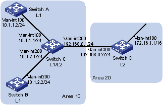
Figure 4-14 Network diagram for IS-IS basic configuration
III. Configuration procedure
1) Configure IP addresses for interfaces (omitted)
2) Configure IS-IS
# Configure Switch A.
<SwitchA> system-view
[SwitchA] isis 1
[SwitchA-isis-1] is-level level-1
[SwitchA-isis-1] network-entity 10.0000.0000.0001.00
[SwitchA-isis-1] quit
[SwitchA] interface vlan-interface 100
[SwitchA-Vlan-interface100] isis enable 1
[SwitchA-Vlan-interface100] quit
# Configure Switch B.
<SwitchB> system-view
[SwitchB] isis 1
[SwitchB-isis-1] is-level level-1
[SwitchB-isis-1] network-entity 10.0000.0000.0002.00
[SwitchB-isis-1] quit
[SwitchB] interface vlan-interface 200
[SwitchB-Vlan-interface200] isis enable 1
[SwitchB-Vlan-interface200] quit
# Configure Switch C.
<SwitchC> system-view
[SwitchC] isis 1
[SwitchC-isis-1] network-entity 10.0000.0000.0003.00
[SwitchC-isis-1] quit
[SwitchC] interface vlan-interface 100
[SwitchC-Vlan-interface100] isis enable 1
[SwitchC-Vlan-interface100] quit
[SwitchC] interface vlan-interface 200
[SwitchC-Vlan-interface200] isis enable 1
[SwitchC-Vlan-interface200] quit
[SwitchC] interface vlan-interface 300
[SwitchC-Vlan-interface300] isis enable 1
[SwitchC-Vlan-interface300] quit
# Configure Switch D.
<SwitchD> system-view
[SwitchD] isis 1
[SwitchD-isis-1] is-level level-2
[SwitchD-isis-1] network-entity 20.0000.0000.0004.00
[SwitchD-isis-1] quit
[SwitchD] interface vlan-interface 100
[SwitchD-Vlan-interface100] isis enable 1
[SwitchD-Vlan-interface100] quit
[SwitchD] interface vlan-interface 300
[SwitchD-Vlan-interface300] isis enable 1
[SwitchD-Vlan-interface300] quit
3) Verify the configuration
# Display the IS-IS LSDB of each switch to check the LSP integrity.
[SwitchA] display isis lsdb
Database information for ISIS(1)
--------------------------------
Level-1 Link State Database
LSPID Seq Num Checksum Holdtime Length ATT/P/OL
--------------------------------------------------------------------------
0000.0000.0001.00-00* 0x00000004 0xdf5e 1096 68 0/0/0
0000.0000.0002.00-00 0x00000004 0xee4d 1102 68 0/0/0
0000.0000.0002.01-00 0x00000001 0xdaaf 1102 55 0/0/0
0000.0000.0003.00-00 0x00000009 0xcaa3 1161 111 1/0/0
0000.0000.0003.01-00 0x00000001 0xadda 1112 55 0/0/0
*-Self LSP, +-Self LSP(Extended), ATT-Attached, P-Partition, OL-Overload
[SwitchB] display isis lsdb
Database information for ISIS(1)
--------------------------------
Level-1 Link State Database
LSPID Seq Num Checksum Holdtime Length ATT/P/OL
--------------------------------------------------------------------------
0000.0000.0001.00-00 0x00000006 0xdb60 988 68 0/0/0
0000.0000.0002.00-00* 0x00000008 0xe651 1189 68 0/0/0
0000.0000.0002.01-00* 0x00000005 0xd2b3 1188 55 0/0/0
0000.0000.0003.00-00 0x00000014 0x194a 1190 111 1/0/0
0000.0000.0003.01-00 0x00000002 0xabdb 995 55 0/0/0
*-Self LSP, +-Self LSP(Extended), ATT-Attached, P-Partition, OL-Overload
[SwitchC] display isis lsdb
Database information for ISIS(1)
--------------------------------
Level-1 Link State Database
LSPID Seq Num Checksum Holdtime Length ATT/P/OL
--------------------------------------------------------------------------
0000.0000.0001.00-00 0x00000006 0xdb60 847 68 0/0/0
0000.0000.0002.00-00 0x00000008 0xe651 1053 68 0/0/0
0000.0000.0002.01-00 0x00000005 0xd2b3 1052 55 0/0/0
0000.0000.0003.00-00* 0x00000014 0x194a 1051 111 1/0/0
0000.0000.0003.01-00* 0x00000002 0xabdb 854 55 0/0/0
*-Self LSP, +-Self LSP(Extended), ATT-Attached, P-Partition, OL-Overload
Level-2 Link State Database
LSPID Seq Num Checksum Holdtime Length ATT/P/OL
--------------------------------------------------------------------------
0000.0000.0003.00-00* 0x00000012 0xc93c 842 100 0/0/0
0000.0000.0004.00-00 0x00000026 0x331 1173 84 0/0/0
0000.0000.0004.01-00 0x00000001 0xee95 668 55 0/0/0
*-Self LSP, +-Self LSP(Extended), ATT-Attached, P-Partition, OL-Overload
[SwitchD] display isis lsdb
Database information for ISIS(1)
--------------------------------
Level-2 Link State Database
LSPID Seq Num Checksum Holdtime Length ATT/P/OL
--------------------------------------------------------------------------
0000.0000.0003.00-00 0x00000013 0xc73d 1003 100 0/0/0
0000.0000.0004.00-00* 0x0000003c 0xd647 1194 84 0/0/0
0000.0000.0004.01-00* 0x00000002 0xec96 1007 55 0/0/0
*-Self LSP, +-Self LSP(Extended), ATT-Attached, P-Partition, OL-Overload
# Display the IS-IS routing information of each switch. Level-1 switches should have a default route with the next hop being the Level-1-2 switch. The Level-2 switch should have both routing information of Level-1 and Level-2.
[SwitchA] display isis route
Route information for ISIS(1)
-----------------------------
ISIS(1) IPv4 Level-1 Forwarding Table
-------------------------------------
IPV4 Destination IntCost ExtCost ExitInterface NextHop Flags
--------------------------------------------------------------------------
10.1.1.0/24 10 NULL Vlan100 Direct D/L/-
10.1.2.0/24 20 NULL Vlan100 10.1.1.1 R/-/-
192.168.0.0/24 20 NULL Vlan100 10.1.1.1 R/-/-
0.0.0.0/0 10 NULL Vlan100 10.1.1.1 R/-/-
Flags: D-Direct, R-Added to RM, L-Advertised in LSPs, U-Up/Down Bit Set
[SwitchC] display isis route
Route information for ISIS(1)
-----------------------------
ISIS(1) IPv4 Level-1 Forwarding Table
-------------------------------------
IPV4 Destination IntCost ExtCost ExitInterface NextHop Flags
--------------------------------------------------------------------------
192.168.0.0/24 10 NULL Vlan300 Direct D/L/-
10.1.1.0/24 10 NULL Vlan100 Direct D/L/-
10.1.2.0/24 10 NULL Vlan200 Direct D/L/-
Flags: D-Direct, R-Added to RM, L-Advertised in LSPs, U-Up/Down Bit Set
ISIS(1) IPv4 Level-2 Forwarding Table
-------------------------------------
IPV4 Destination IntCost ExtCost ExitInterface NextHop Flags
--------------------------------------------------------------------------
192.168.0.0/24 10 NULL Vlan300 Direct D/L/-
10.1.1.0/24 10 NULL Vlan100 Direct D/L/-
10.1.2.0/24 10 NULL Vlan200 Direct D/L/-
172.16.0.0/16 20 NULL Vlan300 192.168.0.2 R/-/-
Flags: D-Direct, R-Added to RM, L-Advertised in LSPs, U-Up/Down Bit Set
[SwitchD] display isis route
Route information for ISIS(1)
-----------------------------
ISIS(1) IPv4 Level-2 Forwarding Table
-------------------------------------
IPV4 Destination IntCost ExtCost ExitInterface NextHop Flags
--------------------------------------------------------------------------
192.168.0.0/24 10 NULL Vlan300 Direct D/L/-
10.1.1.0/24 20 NULL Vlan300 192.168.0.1 R/-/-
10.1.2.0/24 20 NULL Vlan300 192.168.0.1 R/-/-
172.16.0.0/16 10 NULL Vlan100 Direct D/L/-
Flags: D-Direct, R-Added to RM, L-Advertised in LSPs, U-Up/Down Bit Set
4.8.2 DIS Selection Configuration
I. Network requirements
As shown in Figure 4-15, Switch A, B, C and Switch D reside in IS-IS area 10 on a broadcast network (Ethernet). Switch A and Switch B are Level-1-2 switches, Switch C is a Level-1 switch, and Switch D is a Level-2 switch.
Change the DIS priority of Switch A to make it selected as the Level-1-2 DIS router.
II. Network diagram

Figure 4-15 Network diagram for DIS selection
III. Configuration procedure
1) Configure an IP address for each interface (omitted)
2) Enable IS-IS
# Configure Switch A.
<SwitchA> system-view
[SwitchA] isis 1
[SwitchA-isis-1] network-entity 10.0000.0000.0001.00
[SwitchA-isis-1] quit
[SwitchA] interface vlan-interface 100
[SwitchA-Vlan-interface100] isis enable 1
[SwitchA-Vlan-interface100] quit
# Configure Switch B.
<SwitchB> system-view
[SwitchB] isis 1
[SwitchB-isis-1] network-entity 10.0000.0000.0002.00
[SwitchB-isis-1] quit
[SwitchB] interface vlan-interface 100
[SwitchB-Vlan-interface100] isis enable 1
[SwitchB-Vlan-interface100] quit
# Configure Switch C.
<SwitchC> system-view
[SwitchC] isis 1
[SwitchC-isis-1] network-entity 10.0000.0000.0003.00
[SwitchC-isis-1] is-level level-1
[SwitchC-isis-1] quit
[SwitchC] interface vlan-interface 100
[SwitchC-Vlan-interface100] isis enable 1
[SwitchC-Vlan-interface100] quit
# Configure Switch D.
<SwitchD> system-view
[SwitchD] isis 1
[SwitchD-isis-1] network-entity 10.0000.0000.0004.00
[SwitchD-isis-1] is-level level-2
[SwitchD-isis-1] quit
[SwitchD] interface vlan-interface 100
[SwitchD-Vlan-interface100] isis enable 1
[SwitchD-Vlan-interface100] quit
# Display information about IS-IS neighbors of Switch A.
[SwitchA] display isis peer
Peer information for ISIS(1)
----------------------------
System Id: 0000.0000.0002
Interface: Vlan-interface100 Circuit Id: 0000.0000.0003.01
State: Up HoldTime: 21s Type: L1(L1L2) PRI: 64
System Id: 0000.0000.0003
Interface: Vlan-interface100 Circuit Id: 0000.0000.0003.01
State: Up HoldTime: 27s Type: L1 PRI: 64
System Id: 0000.0000.0002
Interface: Vlan-interface100 Circuit Id: 0000.0000.0004.01
State: Up HoldTime: 28s Type: L2(L1L2) PRI: 64
System Id: 0000.0000.0004
Interface: Vlan-interface100 Circuit Id: 0000.0000.0004.01
State: Up HoldTime: 30s Type: L2 PRI: 64
# Display information about IS-IS interfaces of Switch A.
[SwitchA] display isis interface
Interface information for ISIS(1)
---------------------------------
Interface: Vlan-interface100
Id IPV4.State IPV6.State MTU Type DIS
001 Up Down 1497 L1/L2 No/No
# Display information about IS-IS interfaces of Switch C.
[SwitchC] display isis interface
Interface information for ISIS(1)
---------------------------------
Interface: Vlan-interface100
Id IPV4.State IPV6.State MTU Type DIS
001 Up Down 1497 L1/L2 Yes/No
# Display information about IS-IS interfaces of Switch D.
[SwitchD] display isis interface
Interface information for ISIS(1)
---------------------------------
Interface: Vlan-interface100
Id IPV4.State IPV6.State MTU Type DIS
001 Up Down 1497 L1/L2 No/Yes
& Note:
By using the default DIS priority, Switch C is the Level-1 DIS, and Switch D is the Level-2 DIS. The pseudonodes of Level-1 and Level-2 are 0000.0000.0003.01 and 0000.0000.0004.01 respectively.
3) Configure the DIS priority of Switch A.
[SwitchA] interface vlan-interface 100
[SwitchA-Vlan-interface100] isis dis-priority 100
[SwitchA-Vlan-interface100] quit
# Display IS-IS neighbors of Switch A.
[SwitchA] display isis peer
Peer information for ISIS(1)
----------------------------
System Id: 0000.0000.0002
Interface: Vlan-interface100 Circuit Id: 0000.0000.0001.01
State: Up HoldTime: 21s Type: L1(L1L2) PRI: 64
System Id: 0000.0000.0003
Interface: Vlan-interface100 Circuit Id: 0000.0000.0001.01
State: Up HoldTime: 27s Type: L1 PRI: 64
System Id: 0000.0000.0002
Interface: Vlan-interface100 Circuit Id: 0000.0000.0001.01
State: Up HoldTime: 28s Type: L2(L1L2) PRI: 64
System Id: 0000.0000.0004
Interface: Vlan-interface100 Circuit Id: 0000.0000.0001.01
State: Up HoldTime: 30s Type: L2 PRI: 64
# Display information about IS-IS interfaces of Switch A.
[SwitchA] display isis interface
Interface information for ISIS(1)
---------------------------------
Interface: Vlan-interface100
Id IPV4.State IPV6.State MTU Type DIS
001 Up Down 1497 L1/L2 Yes/Yes
& Note:
After the DIS priority configuration, Switch A becomes the Level-1-2 DIS, and the pseudonode is 0000.0000.0001.01.
# Display information about IS-IS neighbors and interfaces of Switch C.
[SwitchC] display isis peer
Peer information for ISIS(1)
----------------------------
System Id: 0000.0000.0002
Interface: Vlan-interface100 Circuit Id: 0000.0000.0001.01
State: Up HoldTime: 25s Type: L1 PRI: 64
System Id: 0000.0000.0001
Interface: Vlan-interface100 Circuit Id: 0000.0000.0001.01
State: Up HoldTime: 7s Type: L1 PRI: 100
[SwitchC] display isis interface
Interface information for ISIS(1)
---------------------------------
Interface: Vlan-interface100
Id IPV4.State IPV6.State MTU Type DIS
001 Up Down 1497 L1/L2 No/No
# Display information about IS-IS neighbors and interfaces of Switch D.
[SwitchD] display isis peer
Peer information for ISIS(1)
----------------------------
System Id: 0000.0000.0001
Interface: Vlan-interface100 Circuit Id: 0000.0000.0001.01
State: Up HoldTime: 9s Type: L2 PRI: 100
System Id: 0000.0000.0002
Interface: Vlan-interface100 Circuit Id: 0000.0000.0001.01
State: Up HoldTime: 28s Type: L2 PRI: 64
[SwitchD] display isis interface
Interface information for ISIS(1)
---------------------------------
Interface: Vlan-interface100
Id IPV4.State IPV6.State MTU Type DIS
001 Up Down 1497 L1/L2 No/No
4.8.3 IS-IS-based Graceful Restart Configuration Example
I. Network requirements
Switch A, Switch B, and Switch C belong to the same IS-IS routing domain, as illustrated in Figure 4-16.
II. Network diagram
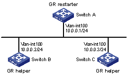
Figure 4-16 Network diagram for IS-IS-based GR configuration
III. Configuration procedure
1) Configure IP addresses of the interfaces on each switch and configure IS-IS.
Follow Figure 4-16 to configure the IP address and subnet mask of each interface. The configuration procedure is omitted.
Configure IS-IS on the switches, ensuring that Switch A, Switch B and Switch C can communicate with each other at layer 3 and dynamic route update can be implemented among them with IS-IS. The configuration procedure is omitted here.
2) Configure IS-IS Graceful Restart.
# Enable IS-IS Graceful Restart on Switch A and configure the Graceful Restart Interval.
<SwitchA> system-view
[SwitchA] isis 1
[SwitchA-isis-1] graceful-restart
[SwitchA-isis-1] graceful-restart interval 150
[SwitchA-isis-1] return
Configurations for Switch B and Switch C are similar and therefore are omitted here.
3) Verify the configuration.
After Router A establishes adjacencies with Router B and Router C, they begin to exchange routing information. Restart IS-IS on Router A, which enters into the restart state and sends connection requests to its neighbors through the Graceful Restart mechanism to synchronize the LSDB. Using the display isis graceful-restart status command can display the IS-IS GR status on Router A.
# Restart Switch A.
<SwitchA> reset isis all 1
Warning : Reset ISIS process? [Y/N]:y
# Check the Graceful Restart status of IS-IS on Switch A.
<SwitchA> display isis graceful-restart status
Restart information for ISIS(1)
-------------------------------
IS-IS(1) Level-1 Restart Status
Restart Interval: 150
SA Bit Supported
Total Number of Interfaces = 1
Restart Status: RESTARTING
T3 Timer Status:
Remaining Time: 65535
T2 Timer Status:
Remaining Time: 59
Interface Vlan1
T1 Timer Status:
Remaining Time: 1
RA Not Received
Complete CSNP Not Received
Number of T1 Pre Expiry: 0
IS-IS(1) Level-2 Restart Status
Restart Interval: 150
SA Bit Supported
Total Number of Interfaces = 1
Restart Status: RESTARTING
T3 Timer Status:
Remaining Time: 65535
T2 Timer Status:
Remaining Time: 59
Interface Vlan1
T1 Timer Status:
Remaining Time: 1
RA Not Received
Complete CSNP Not Received
Number of T1 Pre Expiry: 0
Chapter 5 BGP Configuration
The Border Gateway Protocol (BGP) is a dynamic inter-AS route discovery protocol.
When configuring BGP, go to these sections for information you are interested in:
l Configuring BGP Basic Functions
l Controlling Route Distribution and Reception
l Configuring BGP Route Attributes
l Tuning and Optimizing BGP Networks
l Configuring a Large Scale BGP Network
l Displaying and Maintaining BGP
& Note:
l The term “router” refers to a router in a generic sense or a Layer 3 switch, and BGP refers to BGP-4 in this document.
l The value ranges of the parameters of the commands in this manual use the ranges assuming the switch operate in the default mode. When the switch operates in the IPv4/IPv6 dual-stack or the MCE mode, the value ranges of some parameters may vary. For the operating modes of the switch, refer to the parts discussing IPv6 configuration and MCE
5.1 BGP Overview
Three early versions of BGP are BGP-1 (RFC1105), BGP-2 (RFC1163) and BGP-3 (RFC1267). The current version in use is BGP-4 (RFC1771). BGP-4 is rapidly becoming the defacto Internet exterior routing protocol standard and is commonly used between ISPs.
The characteristics of BGP are as follows:
l Focusing on the control of route propagation and the selection of optimal routes rather than the discovery and calculation of routes, which makes BGP, an exterior routing protocol different from interior routing protocols such as OSPF and RIP
l Using TCP as its transport layer protocol to enhance reliability
l Supporting CIDR
l Substantially reducing bandwidth occupation by advertising updating routes only and applicable to advertising a great amount of routing information on the Internet
l Eliminating route loops completely by adding AS path information to BGP routes
l Providing abundant routing policies to implement flexible route filtering and selection
l Easy to extend, satisfying new network developments
A router advertising BGP messages is called a BGP speaker, which exchanges new routing information with other BGP speakers. When a BGP speaker receives a new route or a route better than the current one from another AS, it will advertise the route to all the other BGP speakers in the local AS.
BGP speakers call each other peers, and several associated peers form a peer group.
BGP runs on a router in one of the following two modes:
l IBGP (Interior BGP)
l EBGP (External BGP)
BGP is called IBGP when it runs within an AS and is called EBGP when it runs between ASs.
5.1.1 Formats of BGP Messages
I. Header
BGP has five types of messages:
l Open
l Update
l Notification
l Keep-alive
l Route-refresh
They have the same header, as shown below:
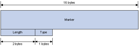
Figure 5-1 BGP message header
l Marker: The 16-byte field is used for BGP authentication. If no authentication information is available, then the Marker must be all ones.
l Length: The 2-byte unsigned integer indicates the total length of the message.
l Type: This 1-byte unsigned integer indicates the type code of the message. The following type codes are defined: 1–Open, 2-Update, 3-Notification, 4–Keepalive, and 5–Route-refresh. The former four are defined in RFC1771, the last one defined in RFC2918.
II. Open
After a TCP connection is established, the first message sent by each side is an Open message for peer relationship establishment. The Open message contains the following fields:
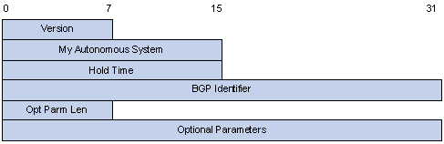
Figure 5-2 BGP open message format
l Version: This 1-byte unsigned integer indicates the protocol version number of the message. The current BGP version is 4.
l My Autonomous System: This 2-byte unsigned integer indicates the Autonomous System number of the sender.
l Hold Time: When establishing peer relationship, two parties negotiate an identical hold time. If no Keepalive or Update is received from a peer after the hold time, the BGP connection is considered down.
l BGP Identifier: In IP address format, identifying the BGP router
l Opt Parm Len (Optional Parameters Length): Length of optional parameters, set to 0 if no optional parameter is available
III. Update
The Update messages are used to exchange routing information between peers. It can advertise a feasible route or remove multiple unfeasible routes. Its format is shown below:
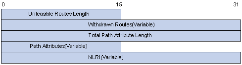
Figure 5-3 BGP Update message format
Each Update message can advertise a group of feasible routes with similar attributes, which are contained in the network layer reachable information (NLRI) field. The Path Attributes field carries attributes of these routes that are used by BGP for routing. Each message can also carry multiple withdrawn routes in the Withdrawn Routes field.
l Unfeasible Routes Length: The total length of the Withdrawn Routes field in bytes. A value of 0 indicates neither any route is being withdrawn from service, nor Withdrawn Routes field is present in this Update message.
l Withdrawn Routes: This is a variable length field that contains a list of IP prefixes of routes that are being withdrawn from service.
l Total Path Attribute Length: Total length of the Path Attributes field in bytes. A value of 0 indicates that no Network Layer Reachability Information field is present in this Update message.
l Path Attributes: List of path attributes related to NLRI. Each path attribute is a triple <attribute type, attribute length, attribute value> of variable length. BGP uses these attributes to avoid routing loops, perform routing and protocol extension.
l NLRI (Network Layer Reachability Information): Reachability information is encoded as one or more 2-tuples of the form <length, prefix>.
IV. Notification
A Notification message is sent when an error is detected. The BGP connection is closed immediately after sending it. Notification message format is shown below:
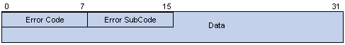
Figure 5-4 BGP Notification message format
l Error Code: Type of Notification.
l Error Subcode: Specific information about the nature of the reported error.
l Data: Used to diagnose the reason for the Notification. The contents of the Data field depend upon the Error Code and Error Subcode. Erroneous part of data is recorded. The Data field length is variable.
V. Keepalive
Keepalive messages are sent between peers to maintain connectivity. Its format contains only the message header.
VI. Route-refresh
A route-refresh message is sent to a peer to request the resending of the specified address family routing information. Its format is shown below:
![]()
Figure 5-5 BGP Route-refresh message format
AFI: Address Family Identifier.
Res: Reserved. Set to 0.
SAFI: Subsequent Address Family Identifier.
5.1.2 BGP Path Attributes
I. Classification of path attributes
Path attributes fall into four categories:
l Well-known mandatory: Must be recognized by all BGP routers and must be included in every update message. Routing information error occurs without this attribute.
l Well-known discretionary: Can be recognized by all BGP routers and optional to be included in every update message as needed.
l Optional transitive: Transitive attribute between ASs. A BGP router not supporting this attribute can still receive routes with this attribute and advertise them to other peers.
l Optional non-transitive: If a BGP router does not support this attribute, it will not advertise routes with this attribute.
The usage of each BGP path attribute is described in the following table.
Table 5-1 Usage of BGP path attributes
|
Name |
Category |
|
ORIGIN |
Well-known mandatory |
|
AS_PATH |
Well-known mandatory |
|
NEXT_HOP |
Well-known mandatory |
|
LOCAL_PREF |
Well-known discretionary |
|
ATOMIC_AGGREGATE |
Well-known discretionary |
|
AGGREGATOR |
Optional transitive |
|
COMMUNITY |
Optional transitive |
|
MULTI_EXIT_DISC (MED) |
Optional non-transitive |
|
ORIGINATOR_ID |
Optional non-transitive |
|
CLUSTER_LIST |
Optional non-transitive |
II. Usage of BGP path attributes
1) ORIGIN
ORIGIN is a well-known mandatory attribute and defines the origin of routing information and how a route becomes a BGP route. It involves three types:
l IGP: Has the highest priority. Routes added to the BGP routing table using the network command have the IGP attribute.
l EGP: Has the second highest priority. Routes obtained via EGP have the EGP attribute.
l incomplete: Has the lowest priority. The source of routes with this attribute is unknown, which does not mean such routes are unreachable. The routes redistributed from other routing protocols have the incomplete attribute.
2) AS_PATH
AS_PATH is a well-known mandatory attribute. This attribute identifies the autonomous systems through which routing information carried in this Update message has passed. When a route is advertised from the local AS to another AS, each passed AS number is added into the AS_PATH attribute, thus the receiver can determine ASs to route the massage back. The number of the AS closest to the receiver’s AS is leftmost, as shown below:
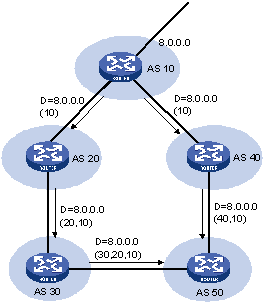
Figure 5-6 AS_PATH attribute
In general, a BGP router does not receive routes containing the local AS number to avoid routing loops.
& Note:
To meet special requirements, use the peer allow-as-loop command to receive routes containing the local AS number.
The AS_PATH attribute can be used for route selection and filtering. BGP gives priority to the route with the shortest AS_PATH length if other factors are the same. As shown in the above figure, the BGP router in AS50 gives priority to the route passing AS40 for sending information to the destination 8.0.0.0.
In some applications, you can apply a routing policy to control BGP route selection by modifying the AS_PATH length.
By configuring an AS path filtering list, you can filter routes based on AS numbers contained in the AS_PATH attribute.
3) NEXT_HOP
Different from IGP, the NEXT_HOP attribute of BGP may not be the IP address of a neighboring router. It involves three types of values, as shown in Figure 5-7.
l When advertising a self-originated route to an EBGP peer, a BGP speaker sets the NEXT_HOP for the route to the address of its sending interface.
l When sending a received route to an EBGP peer, a BGP speaker sets the NEXT_HOP for the route to the address of the sending interface.
l When sending a route received from an EBGP peer to an IBGP peer, a BGP speaker does not modify the NEXT_HOP attribute. If load-balancing is configured, the NEXT_HOP attribute will be modified. For load-balancing information, refer to BGP Route Selection.
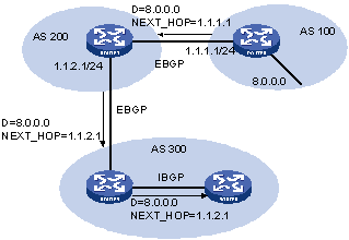
4) MED (MULTI_EXIT_DISC)
The MED attribute is exchanged between two neighboring ASs, each of which does not advertise the attribute to any other AS.
Similar with metrics used by IGP, MED is used to determine the best route for traffic going into an AS. When a BGP router obtains multiple routes to the same destination but with different next hops, it considers the route with the smallest MED value the best route if other conditions are the same. As shown below, traffic from AS10 to AS20 travels through Router B that is selected according to MED.
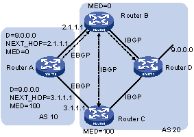
Figure 5-8 MED attribute
In general, BGP compares MEDs of routes to the same AS only.
& Note:
The current implementation supports using the compare-different-as-med command to force BGP to compare MED values of routes to different ASs.
5) LOCAL_PREF
This attribute is exchanged between IBGP peers only, thus not advertised to any other AS. It indicates the priority of a BGP router.
LOCAL_PREF is used to determine the best route for traffic leaving the local AS. When a BGP router obtains from several IBGP peers multiple routes to the same destination but with different next hops, it considers the route with the highest LOCAL_PREF value as the best route. As shown below, traffic from AS20 to AS10 travels through Router C that is selected according to LOCAL_PREF.
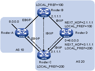
Figure 5-9 LOCAL_PREF attribute
6) COMMUNITY
The COMMUNITY attribute is used to simplify routing policy usage and ease management and maintenance. It is a collection of destination addresses having identical attributes, without physical boundaries in between, and having nothing to do with the local AS. Well known community attributes include:
l Internet: By default, all routes belong to the Internet community. Routes with this attribute can be advertised to all BGP peers.
l No_Export: After received, routes with this attribute cannot be advertised out the local AS or out the local confederation but can be advertised to other sub-ASs in the confederation (for confederation information, refer to Settlements for Problems Caused by Large Scale BGP Networks).
l No_Advertise: After received, routes with this attribute cannot be advertised to other BGP peers.
l No_Export_Subconfed: After received, routes with this attribute cannot be advertised out the local AS or other ASs in the local confederation.
5.1.3 BGP Route Selection
I. Route selection rules
BGP uses the following route selection rules:
l Discard routes with unreachable NEXT_HOP first
l Select the route with the highest Preferred_value
l Select the route with the highest LOCAL_PREF
l Select the route originated by the local router
l Select the route with the shortest AS-PATH
l Select IGP, EGP, Incomplete routes in turn
l Select the route with the lowest MED value
l Select routes learned from EBGP, confederation, IBGP in turn
l Select the route with the smallest next hop cost
l Select the route with the shortest CLUSTER_LIST
l Select the route with the smallest ORIGINATOR_ID
l Select the route advertised by the router with the smallest Router ID
& Note:
l CLUSTER_IDs of route reflectors form a CLUSTER_LIST. If a route reflector receives a route that contains its own CLUSTER ID in the CLUSTER_LIST, the router discards the route to avoid routing loops.
l If load balancing is configured, the system selects available routes to implement load balancing.
II. Route selection with BGP load balancing
The next hop of a BGP route may not be a directly connected neighbor. One of the reasons is next hops in routing information exchanged between IBGPs are not modified. In this case, a router finds the direct route via IGP route entries to reach the next hop. The direct route is called the reliable route. The process of finding a reliable route to reach a next hop is route recursion.
BGP load balancing based on route recursion means that if reliable routes are load balanced (suppose three next hop addresses), BGP generates the same number of next hops to forward packets. Note that BGP load balancing based on route recursion is always enabled by the switch rather than configured using commands.
BGP differs from IGP in the implementation of load balancing in the following:
l IGP routing protocols such as RIP, OSPF compute metrics of routes, and then implement load balancing on routes with the same metric and to the same destination. The route selection criterion is metric.
l BGP has no route computation algorithm, so it cannot implement load balancing according to metrics of routes. However, BGP has abundant route selection rules, through which, it selects available routes for load balancing and adds load balancing to route selection rules.
& Note:
l BGP implements load balancing only on routes that have the same AS_PATH, ORIGIN, LOCAL_PREF and MED.
l BGP load balancing is applicable between EBGPs, between IBGPs and between confederations.
l If multiple routes to the same destination are available, BGP selects routes for load balancing according to the configured maximum number of load balanced routes.
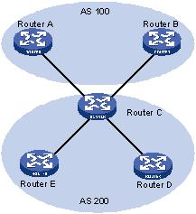
Figure 5-10 Network diagram for BGP load balancing
In the above figure, Router D and Router E are IBGP peers of Router C. Router A and Router B both advertise a route destined for the same destination to Router C. If load balancing is configured and the two routes have the same AS_PATH attribute, ORIGIN attribute, LOCAL_PREF and MED, Router C installs both the two routes to its route table for load balancing. After that, Router C forwards routes to Router D and Router E only once, with AS_PATH unchanged, NEXT_HOP changed to Router C’s address. Other BGP transitive attributes apply according to route selection rules.
III. BGP route advertisement rules
BGP uses the following route advertisement rules:
l When multiple feasible routes exist, a BGP speaker advertises only the best route to its peers.
l A BGP speaker advertises only routes used by itself.
l A BGP speaker advertises routes learned through EBGP to all BGP peers, including both EBGP and IBGP peers.
l A BGP speaker does not advertise IBGP routes to IBGP peers.
l A BGP speaker advertises IBGP routes to EBGP peers. Note that if BGP and IGP synchronization is disabled, IBGP routes are advertised to EBGP peers directly. If the feature is enabled, only IGP advertises the IBGP routes can BGP advertise these routes to EBGP peers.
l A BGP speaker advertises all routes to a newly connected peer.
5.1.4 IBGP and IGP Synchronization
The routing information synchronization between IBGP and IGP is for avoidance of giving wrong directions to routers outside of the local AS.
If a non-BGP router works in an AS, a packet forwarded via the router may be discarded due to an unreachable destination. As shown in Figure 5-11, Router E learned a route of 8.0.0.0/8 from Router D via BGP. Then Router E sends a packet to Router A through Router D, which finds from its routing table that Router B is the next hop (configured using the peer next-hop-local command). Since Router D learned the route to Router B via IGP, it forwards the packet to Router C using route recursion. Router C has no idea about the route 8.0.0.0/8, so it discards the packet.
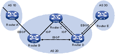
Figure 5-11 IBGP and IGP synchronization
If synchronization is configured in this example, the IBGP router (Router D) checks the learned IBGP route from its IGP routing table first. Only the route is available in the IGP routing table can the IBGP router add the route into its BGP routing table and advertise the route to the EBGP peer.
You can disable the synchronization feature in the following cases:
l The local AS is not a transitive AS (AS20 is a transitive AS in the above figure).
l IBGP routers in the local AS are fully meshed.
5.1.5 Settlements for Problems Caused by Large Scale BGP Networks
I. Route summarization
The size of BGP routing tables on a large network is very large. Using route summarization can reduce the routing table size.
By summarizing multiple routes with one route, a BGP router advertises only the summary route rather than any more specific routes.
Route summarization can be manual or automatic. The latter provides for controlling the attribute of a summary route and deciding whether to advertise the route.
II. Route dampening
BGP route dampening is used to solve the issue of route instability such as route flaps, that is, a route comes up and disappears in the routing table frequently.
When a route flap occurs, the routing protocol sends an update to its neighbor, and then the neighbor needs to recalculate routes and modify the routing table. Therefore, frequent route flaps consume large bandwidth and CPU resources even affect normal operation of the network.
In most cases, BGP is used in complex networks, where route changes are very frequent. To solve the problem caused by route flaps, BGP uses route dampening to suppress unstable routes.
BGP route dampening uses a penalty value to judge the stability of a route. The bigger the value, the less stable the route. Each time a route flap occurs (the state change of a route from active to inactive is a route flap), BGP adds a penalty value (1000, which is a fixed number and cannot be changed) to the route. When the penalty value of the route exceeds the suppress value, the route is suppressed. That is, it is neither added into the routing table, nor advertised to other BGP peers.
The penalty value of the suppressed route will reduce to half of the suppress value after a period of time. This period is called Half-life. When the value decreases to the reusable threshold value, the route is added into the routing table and advertised to other BGP peers in update packets.
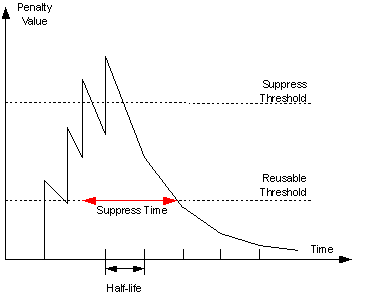
Figure 5-12 BGP route dampening
III. Peer group
A peer group is a collection of peers with the same attributes. When a peer joins the peer group, the peer obtains the same configuration as the peer group. If configuration of the peer group is changed, configuration of group members is also changed.
There are many peers in a large BGP network. Some of these peers may be configured with identical commands. The peer group feature simplifies configuration of this kind.
When a peer is added into a peer group, the peer enjoys the same route update policy as the peer group to improve route distribution efficiency.
![]() Caution:
Caution:
If an option is configured both for a peer and for the peer group, the latest configuration takes effect.
IV. Community
A peer group makes peers in it enjoy the same policy, while a community makes a group of BGP routers in several ASs enjoy the same policy. Community is a path attribute and advertised between BGP peers, without being limited by AS.
A BGP router can modify the community attribute for a route before sending it to other peers.
Besides using the well-known community attribute, you can define the extended community attribute using a community list to help define a routing policy.
V. Route reflector
IBGP peers should be fully meshed to maintain connectivity. If there are n routers in an AS, the number of IBGP connections is n (n-1)/2. Therefore if there are many IBGP peers, most network and CPU resources will be consumed.
Using route reflectors can solve the issue. In an AS, a router acts as a route reflector, and other routers act as clients connecting to the route reflector. The route reflector forwards (reflects) routing information between clients. BGP connections between clients need not be established.
The router neither a route reflector nor a client is a non-client, which has to establish connections to the route reflector and non-clients, as shown below.
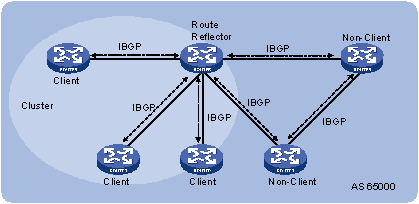
Figure 5-13 Network diagram for route reflector
The route reflector and clients form a cluster. In some cases, you can configure more than one route reflector in a cluster to improve network reliability and prevent the single point failure, as shown in the following figure. The configured route reflectors must have the same Cluster_ID to avoid routing loops.
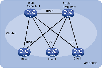
Figure 5-14 Network diagram for route reflectors
When clients of a route reflector are fully meshed, route reflection is unnecessary because it consumes more bandwidth resources. You can use related commands to disable route reflection in this case.
& Note:
After route reflection is disabled between clients, routes between a client and a non-client can still be reflected.
VI. Confederation
Confederation is another method to deal with growing IBGP connections in ASs. It splits an AS into multiple sub-ASs. In each sub-AS, IBGP peers are fully meshed, and EBGP connections are established between sub-ASs, as shown below:
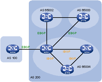
Figure 5-15 Confederation network diagram
From the perspective of a non-confederation speaker, it needs not know sub-ASs in the confederation. The ID of the confederation is the number of the AS. In the above figure, AS200 is the confederation ID.
The deficiency of confederation is: when changing an AS into a confederation, you need to reconfigure your routers, and the topology will be changed.
In large-scale BGP networks, both route reflector and confederation can be used.
5.1.6 BGP GR
& Note:
For GR (Graceful Restart) information, refer to BFD GR Configuration.
1) To establish a BGP session with a peer, a BGP GR Restarter sends an OPEN message with GR capability to the peer.
2) Upon receipt of this message, the peer is aware that the sending router is capable of Graceful Restart, and sends an OPEN message with GR Capability to the GR Restarter to establish a GR session. If neither party has the GR capability, the session established between them will not be GR capable.
3) The GR session between the GR Restarter and its peer goes down when the GR Restarter restarts BGP. The GR capable peer will mark all routes associated with the GR Restarter as stale. However, during the configured GR Time, it still uses these routes for packet forwarding, ensuring that no packet will be lost when routing information from its peer is recollected.
4) After the restart, the GR Restarter will reestablish a GR session with its peer and send a new GR message notifying the completion of restart. Routing information is exchanged between them for the GR Restarter to create a new routing table and forwarding table with stale routing information removed. Thus the BGP routing convergence is complete.
5.1.7 MP-BGP
I. Overview
The legacy BGP-4 supports IPv4, but does not support other network layer protocols like IPv6.
To support more network layer protocols, IETF extended BGP-4 by introducing Multiprotocol Extensions for BGP-4 (MP-BGP), which is defined in RFC2858.
Routers supporting MP-BGP can communicate with routers not supporting MP-BGP.
II. MP-BGP extended attributes
In BGP-4, the three types of attributes for IPv4, namely NLRI, NEXT_HOP and AGGREGATOR (contains the IP address of the speaker generating the summary route) are all carried in updates.
To support multiple network layer protocols, BGP-4 puts information about network layer into NLRI and NEXT_HOP. MP-BGP introduced two path attributes:
l MP_REACH_NLRI: Multiprotocol Reachable NLRI, for advertising feasible routes and next hops
l MP_UNREACH_NLRI: Multiprotocol Unreachable NLRI, for withdrawing unfeasible routes
The above two attributes are both optional non-transitive, so BGP speakers not supporting multi-protocol ignore the two attributes and do not forward them to peers.
III. Address family
MP-BGP employs address family to differentiate network layer protocols. For address family values, refer to RFC 1700 (Assigned Numbers). Currently, the system supports multiple MP-BGP extensions, including VPN extension, IPv6 extension. Different extensions are configured in respective address family view.
& Note:
l For information about the VPN extension application, refer to the part discussing MCE configuration.
l For information about the IPv6 extension application, refer to IPv6 BGP Configuration in IPv6 Routing.
l This chapter gives no detailed commands related to any specific extension application in MP-BGP address family view.
5.1.8 Protocols and Standards
l RFC1771: A Border Gateway Protocol 4 (BGP-4)
l RFC2858: Multiprotocol Extensions for BGP-4
l RFC3392: Capabilities Advertisement with BGP-4
l RFC2918: Route Refresh Capability for BGP-4
l RFC2439: BGP Route Flap Damping
l RFC1997: BGP Communities Attribute
l RFC2796: BGP Route Reflection
l RFC3065: Autonomous System Confederations for BGP
l draft-ietf-idr-restart-08: Graceful Restart Mechanism for BGP
5.2 BGP Configuration Task List
Complete the following tasks to configure BGP:
|
Task |
Remarks |
|
|
Required |
||
|
Optional |
||
|
Optional |
||
|
Optional |
||
|
Optional |
||
|
Optional |
||
|
Optional |
||
|
Optional |
||
|
Required |
||
|
Required |
||
|
Optional |
||
|
Optional |
||
|
Optional |
||
|
Optional |
||
|
Optional |
||
5.3 Configuring BGP Basic Functions
The section describes BGP basic configuration.
& Note:
l This section does not differentiate between BGP and MP-BGP.
l Since BGP employs TCP, you need to specify IP addresses of peers, which may not be neighboring routers.
l Using logical links can also establish BGP peer relationships.
l In general, IP addresses of loopback interfaces are used to improve stability of BGP connections.
5.3.1 Prerequisites
The neighboring nodes are accessible to each other at the network layer.
5.3.2 Configuration Procedure
Follow these steps to configure BGP basic functions:
|
To do… |
Use the command… |
Remarks |
|
|
Enter system view |
system-view |
— |
|
|
Enable BGP and enter BGP view |
bgp as-number |
Required Not enabled by default |
|
|
Specify a Router ID |
router-id ip-address |
Optional If no IP addresses are configured for loopback interface and other interfaces, the task becomes required. |
|
|
Specify the AS number of a peer or a peer group |
peer { group-name | ip-address } as-number as-number |
Required Not specified by default |
|
|
Configure a description for a peer or a peer group |
peer { group-name | ip-address } description description-text |
Optional |
|
|
Enable IPv4 unicast address family for all peers |
default ipv4-unicast |
Optional Enabled by default |
|
|
Enable a peer |
Optional Enabled by default |
||
|
Ignore a peer or peer group |
peer { group-name | ip-address } ignore |
Optional Not ignored by default |
|
|
Enable the logging of peer state changes |
globally |
log-peer-change |
Optional Enabled by default |
|
for a peer or peer group |
peer { group-name | ip-address } log-change |
Optional Enabled by default |
|
|
Specify a preferred value for routes from a peer or peer group |
peer { group-name | ip-address } preferred-value value |
Optional The preferred value defaults to 0. |
|
|
Specify the source interface for establishing TCP connections to a peer or peer group |
peer { group-name | ip-address } connect-interface interface-type interface-number |
Optional By default, BGP uses the outbound interface of the best route to the BGP peer as the source interface for establishing a TCP connection. |
|
|
Allow the establishment of EBGP connection to a non directly connected peer/peer group |
peer { group-name | ip-address } ebgp-max-hop [ hop-count ] |
Optional Not allowed by default. By specifying hop-count, you can specify the max hops for the EBGP connection. |
|
l It is required to specify for a BGP router a router ID, a 32-bit unsigned integer and the unique identifier of the router in the AS.
l You can specify a router ID manually. If not, the system selects an IP address as the router ID. The selection sequence is the highest IP address among loopback interface addresses; if not available, then the highest IP address of interfaces. It is recommended to specify a loopback interface address as the router ID to enhance network reliability. Only when the interface with the selected Router ID or the manual Router ID is deleted will the system select another ID for the router.
l You need to create a peer group before configuring it. Refer to Configuring BGP Peer Groups for creating a peer group.
l To establish multiple BGP connections to a BGP router, you need to specify on the local router the respective source interfaces for establishing TCP connections to the peers on the peering BGP router; otherwise, the local BGP router may fail to establish TCP connections to the peers when using the outbound interfaces of the best routes as the source interfaces.
l In general, direct physical links should be available between EBGP peers. If not, you can use the peer ebgp-max-hop command to establish a TCP connection over multiple hops between two peers. You need not use this command for directly connected EBGP peers, which employ loopback interfaces for peer relationship establishment.
l If you both reference a routing policy and use the peer { group-name | ip-address } preferred-value value command to set a preferred value for routes from a peer, the routing policy sets a non-zero preferred value for routes matching it. Other routes not matching the routing policy uses the value set with the command. If the preferred value in the routing policy is zero, the routes matching it will also use the value set with the command. For information about using a routing policy to set a preferred value, refer to the command peer { group-name | ip-address } route-policy route-policy-name { export | import } in this document, and the command apply preferred-value preferred-value in Routing Policy Commands of the IP Routing Volume.
5.4 Controlling Route Distribution and Reception
5.4.1 Prerequisites
Before configuring this task, you have completed BGP basic configuration.
5.4.2 Configuring BGP Route Redistribution
BGP can advertise the routing information of the local AS to peering ASs, but it redistributes routing information from IGP into BGP rather than self-finding. During route redistribution, BGP can filter routing information from specific routing protocols.
Follow these steps to configure BGP route redistribution:
|
To do… |
Use the command… |
Remarks |
|
Enter system view |
system-view |
— |
|
Enter BGP view |
bgp as-number |
— |
|
Enable BGP to redistribute default route into the BGP routing table |
default-route imported |
Optional Not enabled by default |
|
Redistribute routes from another routing protocol |
import-route protocol [ process-id [ med med-value | route-policy route-policy-name ] * ] |
Required Not redistributed by default |
|
Inject a network to the BGP routing table |
network ip-address [ mask | mask-length ] [ short-cut | route-policy route-policy-name ] |
Optional Not injected by default |
& Note:
l The ORIGIN attribute of routes redistributed using the import-route command is Incomplete.
l The ORIGIN attribute of networks advertised into the BGP routing table with the network command is IGP. These networks must exist in the local IP routing table, and using a routing policy makes routes control more flexible.
5.4.3 Configuring BGP Route Summarization
To reduce the routing table size on medium and large BGP networks, you need to configure route summarization on peers. BGP supports two summarization modes: automatic and manual.
l Automatic summarization: Summarizes redistributed IGP subnets. With the feature configured, BGP advertises only summary natural networks rather than subnets. The default route and routes injected with the network command can not be summarized.
l Manual summarization: Summarizes BGP local routes. The manual summary routes enjoy higher priority than automatic ones.
Follow these steps to configure BGP route summarization:
|
To do… |
Use the command… |
Remarks |
|
|
Enter system view |
system-view |
— |
|
|
Enter BGP view |
bgp as-number |
— |
|
|
Configure BGP route summarization |
Configure automatic route summarization |
summary automatic |
Required No route summarization is configured by default. Choose either as needed; if both are configured, the manual route summarization takes effect. |
|
Configure manual route summarization |
aggregate ip-address { mask | mask-length } [ as-set | attribute-policy route-policy-name | detail-suppressed | origin-policy route-policy-name | suppress-policy route-policy-name ]* |
||
5.4.4 Advertising a Default Route to a Peer or Peer Group
Follow these steps to advertise a default route to a peer or peer group:
|
To do… |
Use the command… |
Remarks |
|
Enter system view |
system-view |
— |
|
Enter BGP view |
bgp as-number |
— |
|
Advertise a default route to a peer or peer group |
peer { group-name | ip-address } default-route-advertise [ route-policy route-policy-name ] |
Required Not advertised by default |
& Note:
With the peer default-route-advertise command executed, the router sends a default route with the next hop being itself to the specified peer/peer group, regardless of whether the default route is available in the routing table.
5.4.5 Configuring BGP Route Distribution Filtering Policies
Follow these steps to configure BGP route distribution filtering policies:
|
To do… |
Use the command… |
Remarks |
|
Enter system view |
system-view |
— |
|
Enter BGP view |
bgp as-number |
— |
|
Configure the filtering of outgoing redistributed routes |
filter-policy { acl-number | ip-prefix ip-prefix-name } export [ direct | isis process-id | ospf process-id | rip process-id | | static ] |
Required to choose any; Not configured by default; You can configure a filtering policy as needed; If several filtering policies are configured, they are applied in the following sequence: l filter-policy export l peer filter-policy export l peer as-path-acl export l peer ip-prefix export l peer route-policy export Only routes pass the first policy, can they go to the next, and only routes passing all the configured policies, can they be advertised. |
|
Reference a routing policy to filter routes to a peer/peer group |
peer { group-name | ip-address } route-policy route-policy-name export |
|
|
Reference an ACL to filer routes to a peer/peer group |
peer { group-name | ip-address } filter-policy acl-number export |
|
|
Reference an AS path ACL to filter routing information to a peer/peer group |
peer { group-name | ip-address } as-path-acl as-path-acl-number export |
|
|
Reference an IP prefix list to filer routing information to a peer/peer group |
peer { group-name | ip-address } ip-prefix ip-prefix-name export |
5.4.6 Configuring BGP Route Reception Filtering Policies
Follow these steps to configure BGP route reception filtering policies:
|
To do… |
Use the command… |
Remarks |
|
Enter system view |
system-view |
— |
|
Enter BGP view |
bgp as-number |
— |
|
Filter incoming routes with an ACL or IP prefix list |
filter-policy { acl-number | ip-prefix ip-prefix-name } import |
Required to choose any; No route reception filtering is configured by default; You can configure a filtering policy as needed; If several filtering policies are configured, they are applied in the following sequence: l filter-policy import l peer filter-policy import l peer as-path-acl import l peer ip-prefix import l peer route-policy import Only routes passing the first policy, can they go to the next, and only routes passing all the configured policies, can they be received. |
|
Reference a routing policy to filter routes from a peer/peer group |
peer { group-name | ip-address } route-policy policy-name import |
|
|
Reference an ACL to filter routing information from a peer/peer group |
peer { group-name | ip-address } filter-policy acl-number import |
|
|
Reference an AS path ACL to filter routing information from a peer/peer group |
peer { group-name | ip-address } as-path-acl as-path-acl-number import |
|
|
Reference an IP prefix list to filter routing information from a peer/peer group |
peer { group-name | ip-address } ip-prefix ip-prefix-name import |
|
|
Specify the maximum number of routes that can be received from a peer/peer group |
peer { group-name | ip-address } route-limit limit [ percentage ] |
The number is unlimited by default. |
& Note:
l Only routes permitted by the specified filtering policies can they be installed into the local BGP routing table.
l Members of a peer group can have different route reception filtering policies from the peer group.
5.4.7 Enabling BGP and IGP Route Synchronization
By default, when a BGP router receives an IBGP route, it only checks the reachability of the route’s next hop before advertisement. With BGP and IGP synchronization configured, the BGP router cannot advertise the route to EBGP peers unless the route is also available in the IGP routing table.
Follow these steps to configure BGP and IGP synchronization:
|
To do… |
Use the command… |
Remarks |
|
Enter system view |
system-view |
— |
|
Enter BGP view |
bgp as-number |
— |
|
Enable synchronization between BGP and IGP |
synchronization |
Required Not enabled by default |
5.4.8 Configuring BGP Route Dampening
By configuring BGP route dampening, you can suppress unstable routes from neither adding them to the local routing table nor advertising them to BGP peers.
Follow these steps to configure BGP route dampening:
|
To do… |
Use the command… |
Remarks |
|
Enter system view |
system-view |
— |
|
Enter BGP view |
bgp as-number |
— |
|
Configure BGP route dampening |
dampening [ half-life-reachable half-life-unreachable reuse suppress ceiling | route-policy route-policy-name ] * |
Optional Not configured by default |
5.5 Configuring BGP Route Attributes
5.5.1 Prerequisites
Before configuring this task, you have configured BGP basic functions.
5.5.2 Configuration Procedure
You can configure BGP route attributes to influence BGP route selection.
Follow these steps to configure BGP route attributes:
|
To do… |
Use the command… |
Remarks |
||
|
Enter system view |
system-view |
— |
||
|
Enter BGP view |
bgp as-number |
— |
||
|
Configure preferences for external, internal, local routes |
preference { external-preference internal-preference local-preference | route-policy route-policy-name } |
Optional The default preferences of external, internal, and local routes are 255, 255, and 130 respectively. |
||
|
Configure the default local preference |
default local-preference value |
Optional 100 by default |
||
|
Configure the MED attribute |
Configure the default MED value |
default med med-value |
Optional 0 by default |
|
|
Enable the comparison of MED of routes from different ASs |
compare-different-as-med |
Optional Not enabled by default |
||
|
Enable the comparison of MED of routes from each AS |
bestroute compare-med |
Optional Not enabled by default |
||
|
Enable the comparison of MED of routes from confederation peers |
bestroute med-confederation |
Optional Not enabled by default |
||
|
Specify the router as the next hop of routes to a peer/peer group |
peer { group-name | ip-address } next-hop-local |
Optional By default, routes to an EBGP peer/peer group take the router as the next hop, while routes to an IBGP peer/peer group do not take the local router as the next hop. |
||
|
Configure the AS_PATH attribute |
Configure repeating times of local AS number in routes from a peer/peer group |
peer { group-name | ip-address } allow-as-loop [ number ] |
Optional The local AS number can not be repeated in routes from the peer/peer group. |
|
|
Disable the router from taking AS_PATH as a factor for best route selection |
bestroute as-path-neglect |
Optional By default, the router takes AS_PATH as a factor for best route selection. |
||
|
Specify a fake AS number for a peer/peer group |
peer { group-name | ip-address } fake-as as-number |
Optional Not specified by default This command is only applicable to an EBGP peer or peer group. |
||
|
Substitute local AS number for the AS number of a peer/peer group in the AS_PATH attribute |
peer { group-name | ip-address } substitute-as |
Optional The substitution is not configured by default. |
||
|
Configure to not keep private AS number in AS_PATH of updates to a peer/peer group |
peer { group-name | ip-address } public-as-only |
Optional By default, BGP updates carry private AS numbers. |
||
& Note:
l Using a routing policy can set preferences for routes matching it. Routes not matching it use the default preferences.
l If other conditions are identical, the route with the smallest MED value is selected as the best external route.
l Using the peer next-hop-local command can specify the router as the next hop for routes to a peer/peer group. If BGP load balancing is configured, the router specify itself as the next hop for routes to a peer/peer group regardless of whether the peer next-hop-local command is configured.
l In a “third party next hop" network, that is , the two EBGP peers reside in a common broadcast subnet, the BGP router does not specify itself as the next hop for routes to the EBGP peer, unless the peer next-hop-local command is configured.
l In general, BGP checks whether the AS_PATH attribute of a route from a peer contains the local AS number. If so, it discards the route to avoid routing loops.
l You can specify a fake AS number to hide the real one as needed. The fake AS number applies to routes to EBGP peers only, that is, EBGP peers in other ASs can only find the fake AS number.
l The peer substitute-as command is used only in specific networking environments. Inappropriate use of the command may cause routing loops.
5.6 Tuning and Optimizing BGP Networks
This task involves the following parts:
1) Configure BGP timers
After establishing a BGP connection, two routers send keepalive messages periodically to each other to keep the connection. If a router receives no keepalive message from the peer after the holdtime elapses, it tears down the connection.
When establishing a BGP connection, the two parties compare their hold time values, taking the shorter one as the common holdtime.
2) Reset BGP connections
After modifying a route selection policy, you have to reset BGP connections to make the new one take effect, causing short time disconnections. The current BGP implementation supports the route-refresh capability. With this capability enabled on all BGP routers in a network, when a policy is modified on a router, the router advertises a route-refresh message to its peers, which then resend their routing information to the router. Therefore, the local router can perform dynamic route update and apply the new policy without tearing down BGP connections.
If a router not supporting route-refresh exists in the network, you must configure the peer keep-all-routes command to save all route updates, and then use the refresh bgp command to soft-reset BGP connections, to refresh the BGP routing table and apply the new policy without tearing down BGP connections.
3) Configure BGP authentication
BGP employs TCP as the transport protocol. To enhance security, you can configure BGP to perform MD5 authentication when establishing a TCP connection. BGP MD5 authentication is not for BGP packets. It is used to set passwords for TCP connections. If the authentication fails, the TCP connection can not be established.
5.6.1 Prerequisites
Before configuring this task, you have configured BGP basic functions
5.6.2 Configuration Procedure
Follow these steps to tune and optimize BGP networks:
|
To do… |
Use the command… |
Remarks |
|
|
Enter system view |
system-view |
— |
|
|
Enter BGP view |
bgp as-number |
— |
|
|
Configure BGP timers |
Configure keepalive interval and holdtime |
timer keepalive keepalive hold holdtime |
Optional The keepalive interval defaults to 60 seconds, holdtime defaults to 180 seconds. |
|
Configure keepalive interval and holdtime for a peer/peer group |
peer { group-name | ip-address } timer keepalive keepalive hold holdtime |
||
|
Configure the interval for sending the same update to a peer/peer group |
peer { group-name | ip-address } route-update-interval seconds |
Optional The intervals for sending the same update to an IBGP peer and an EBGP peer default to 15 seconds and 30 seconds respectively. |
|
|
Configure BGP soft reset |
Disable BGP route-refresh and multi-protocol extensions for a peer/peer group |
peer { group-name | ip-address } capability-advertise conventional |
Optional Enabled by default |
|
Enable BGP route refresh for a peer/peer group |
peer { group-name | ip-address } capability-advertise route-refresh |
Optional Enabled by default |
|
|
Keep all original routes from a peer/peer group regardless of whether they pass the inbound filtering policy |
peer { group-name | ip-address } keep-all-routes |
Optional Not kept by default |
|
|
Return to user view |
return |
— |
|
|
Perform manual soft reset on BGP connections |
refresh bgp { all | ip-address | group group-name | external | internal } { export | import } |
Required |
|
|
Enter system view |
system-view |
— |
|
|
Enter BGP view |
bgp as-number |
— |
|
|
Enable the clearing of the direct EBGP session on any interface that becomes down |
ebgp-interface-sensitive |
Optional Enabled by default |
|
|
Enable MD5 authentication when establishing a TCP connection to the peer/peer group |
peer { group-name | ip-address } password { cipher | simple } password |
Optional Enabled by default |
|
|
Configure the number of BGP load balanced routes |
balance number |
Optional Load balancing is not enabled by default. |
|
& Note:
l The maximum keepalive interval should be one third of the holdtime and no less than 1 second. The holdtime is no less than 3 seconds unless it is set to 0.
l The intervals set with the peer timer command are preferred to those set with the timer command.
l Use of the peer keep-all-routes command saves all routing updates from the peer regardless of whether any filtering policy is configured. The system uses these updates to rebuild the routing table after a soft reset.
l Performing BGP soft reset can refresh the routing table and apply the new policy without tearing down BGP sessions.
l BGP soft reset requires all routers in the network have the route-refresh capability. If not, you need use the peer keep-all-routes command to keep all routing information from a BGP peer to perform soft reset.
5.7 Configuring a Large Scale BGP Network
In a large-scale BGP network, configuration and maintenance become difficult due to large numbers of BGP peers. In this case, configuring peer groups makes management easier and improves route distribution efficiency. Peer group includes IBGP peer group, where peers belong to the same AS, and EBGP peer group, where peers belong to different ASs. If peers in an EBGP group belong to the same external AS, the EBGP peer group is a pure EBGP peer group, and if not, a mixed EBGP peer group.
Configuring BGP community can also help simplify routing policy management, and a community has a much larger management scope than a peer group by controlling routing policies of multiple BGP routers.
To guarantee the connectivity between IBGP peers, you need to make them fully meshed. But it becomes unpractical when there are large numbers of IBGP peers. Configuring route reflectors or confederation can solve it. In a large-scale AS, both of them can be used.
5.7.1 Configuration Prerequisites
Before configuring this task, you have made peering nodes accessible to each other at the network layer.
5.7.2 Configuring BGP Peer Groups
Follow these steps to configure BGP peer groups:
|
To do… |
Use the command… |
Remarks |
|
|
Enter system view |
system-view |
— |
|
|
Enter BGP view |
bgp as-number |
— |
|
|
Configure an IBGP peer group |
Create an IBGP peer group |
group group-name [ internal ] |
Optional You can add multiple peers into the group. The system will create these peers automatically and specify the local AS number as their AS in BGP view. |
|
Add a peer into the IBGP peer group |
peer ip-address group group-name [ as-number as-number ] |
||
|
Configure a pure EBGP peer group |
Create an EBGP peer group |
group group-name external |
Optional You can add multiple peers into the group. The system will create these peers automatically and specify the local AS number as their AS in BGP view. |
|
Specify the AS number for the group |
peer group-name as-number as-number |
||
|
Add a peer into the group |
peer ip-address group group-name [ as-number as-number ] |
||
|
Configure a mixed EBGP peer group |
Create an EBGP peer group |
group group-name external |
Optional You can add multiple peers into the group. |
|
Specify a peer and the AS number for the peer |
peer ip-address as-number as-number |
||
|
Add a peer into the group |
peer ip-address group group-name [ as-number as-number ] |
||
& Note:
l You need not specify the AS number when creating an IBGP peer group.
l If there are peers in a peer group, you can neither change the AS number of the group nor use the undo command to remove the AS number
l You need specify the AS number for each peer in a mixed EBGP peer group respectively.
5.7.3 Configuring BGP Community
Follow these steps to configure BGP community:
|
To do… |
Use the command… |
Remarks |
|
|
Enter system view |
system-view |
— |
|
|
Enter BGP view |
bgp as-number |
— |
|
|
Advertise the community attribute to a peer/peer group |
Advertise the community attribute to a peer/peer group |
peer { group-name | ip-address } advertise-community |
Required Not configured by default |
|
Advertise the extended community attribute to a peer/peer group |
peer { group-name | ip-address } advertise-ext-community |
||
|
Apply a routing policy to routes advertised to a peer/peer group |
peer { group-name | ip-address } route-policy route-policy-name export |
Required Not configured by default |
|
& Note:
l When configuring BGP community, you need to configure a routing policy to define the community attribute, and apply the routing policy to route advertisement.
l For routing policy configuration, refer to Routing Policy Configuration.
5.7.4 Configuring a BGP Route Reflector
Follow these steps to configure a BGP route reflector:
|
To do… |
Use the command… |
Remarks |
|
Enter system view |
system-view |
— |
|
Enter BGP view |
bgp as-number |
— |
|
Configure the router as a route reflector and specify a peer/peer group as its client |
peer { group-name | ip-address } reflect-client |
Required Not configured by default |
|
Enable route reflection between clients |
reflect between-clients |
Optional Enabled by default |
|
Configure the cluster ID of the route reflector |
reflector cluster-id cluster-id |
Optional By default, a route reflector uses its router ID as the cluster ID. |
& Note:
l In general, it is not required to make clients of a route reflector fully meshed. The route reflector forwards routing information between clients. If clients are fully meshed, you can disable route reflection between clients to reduce routing costs.
l In general, a cluster has only one route reflector, and the router ID is used to identify the cluster. You can configure multiple route reflectors to improve network stability. In this case, you need to specify the same cluster ID for these route reflectors to avoid routing loops.
5.7.5 Configuring a BGP Confederation
Follow these steps to configure a BGP confederation:
|
To do… |
Use the command… |
Remarks |
|
|
Enter system view |
system-view |
— |
|
|
Enter BGP view |
bgp as-number |
— |
|
|
Configure a BGP confederation |
Configure a confederation ID |
confederation id as-number |
Required Not configured by default |
|
Specify sub-ASs contained in the confederation |
confederation peer-as as-number-list |
||
|
Enable compatibility with routers not compliant with RFC 3065 in the confederation |
confederation nonstandard |
Optional Not enabled by default |
|
& Note:
l A confederation contains 32 sub-ASs at most. The as-number of a sub-AS takes effect in the confederation only.
l If routers not compliant with RFC 3065 exist in the confederation, you can use the confederation nonstandard command to make the local router compatible with these routers.
5.8 Configuring BGP GR
Perform the following configuration on the GR Restarter and GR Helper respectively.
& Note:
When configured with BGP GR, the switch can only act as a GR Helper.
Follow these steps to configure BGP GR:
|
To do… |
Use the command… |
Remarks |
|
Enter system view |
system-view |
— |
|
Enter BGP view |
bgp as-number |
— |
|
Enable GR Capability for BGP |
graceful-restart |
Required Disabled by default |
|
Configure the maximum time allowed for the peer to reestablish a BGP session |
graceful-restart timer restart timer |
Optional 150 seconds by default |
|
Configure the maximum time to wait for the End-of-RIB marker |
graceful-restart timer wait-for-rib timer |
Optional 180 seconds by default |
& Note:
l In general the maximum time allowed for the peer (the GR restarter) to reestablish a BGP session should be less than the Holdtime carried in the OPEN message.
l The End-Of-RIB (End of Router-Information-Base) indicates the end of route updates.
5.9 Displaying and Maintaining BGP
5.9.1 Displaying BGP
|
To do… |
Use the command… |
Remarks |
|
Display peer group information |
display bgp group [ group-name ] |
Available in any view |
|
Display advertised BGP routing information |
display bgp network |
|
|
Display AS path information |
display bgp paths [ as-regular-expression ] |
|
|
Display BGP peer/peer group information |
display bgp peer [ ip-address { log-info | verbose } | group-name log-info | verbose ] |
|
|
Display BGP routing information |
display bgp routing-table [ ip-address [ { mask | mask-length } [ longer-prefixes ] ] ] |
|
|
Display routing information matching the AS path ACL |
display bgp routing-table as-path-acl as-path-acl-number |
|
|
Display BGP CIDR routing information |
display bgp routing-table cidr |
|
|
Display BGP routing information matching the specified BGP community |
display bgp routing-table community [ aa:nn&<1-13> ] [ no-advertise | no-export | no-export-subconfed ]* [ whole-match ] |
|
|
Display routing information matching a BGP community list |
display bgp routing-table community-list { basic-community-list-number [ whole-match ] | adv-community-list-number }&<1-16> |
|
|
Display BGP dampened routing information |
||
|
Display BGP dampening parameter information |
display bgp routing-table dampening parameter |
|
|
Display BGP routing information originating from different ASs |
display bgp routing-table different-origin-as |
|
|
Display BGP routing flap statistics |
display bgp routing-table flap-info [ regular-expression as-regular-expression | as-path-acl as-path-acl-number | ip-address [ { mask | mask-length } [ longer-match ] ] ] |
|
|
Display routing information to or from a peer |
display bgp routing-table peer ip-address { advertised-routes | received-routes } [ network-address [ mask | mask-length ] | statistic ] |
|
|
Display routing information matching a regular expression |
display bgp routing-table regular-expression as-regular-expression |
|
|
Display BGP routing statistics |
display bgp routing-table statistic |
5.9.2 Resetting BGP Connections
|
To do… |
Use the command… |
Remarks |
|
Reset all BGP connections |
reset bgp all |
Available in user view |
|
Reset the BGP connections to an AS |
reset bgp as-number |
|
|
Reset the BGP connection to a peer |
reset bgp ip-address [ flap-info ] |
|
|
Reset all EBGP connections |
reset bgp external |
|
|
Reset the BGP connections to a peer group |
reset bgp group group-name |
|
|
Reset all IBGP connections |
reset bgp internal |
|
|
Reset all IPv4 unicast BGP connections |
reset bgp ipv4 all |
5.9.3 Clearing BGP Information
|
To do… |
Use the command… |
Remarks |
|
Clear dampened MBGP routing information and release suppressed routes |
reset bgp dampening [ ip-address [ mask | mask-length ] ] |
Available in user view |
|
Clear route flap information |
reset bgp flap-info [ regexp as-path-regexp | as-path-acl as-path-acl-number | ip-address [ mask | mask-length ] ] |
5.10 BGP Configuration Examples
5.10.1 BGP Basic Configuration
I. Network requirements
In the following figure are all BGP switches. Between Switch A and Switch B is an EBGP connection. IBGP speakers Switch B, Switch C and Switch D are fully meshed.
II. Network diagram
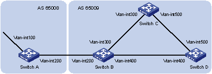
|
Interface |
IP address |
Device |
Interface |
IP address |
|
|
Switch A |
Vlan-int100 |
8.1.1.1/8 |
Switch D |
Vlan-int400 |
9.1.1.2/24 |
|
|
Vlan-int200 |
200.1.1.2/24 |
|
Vlan-int500 |
9.1.2.2/24 |
|
Switch B |
Vlan-int400 |
9.1.1.1/24 |
Switch C |
Vlan-int500 |
9.1.2.1/24 |
|
|
Vlan-int200 |
200.1.1.1/24 |
|
Vlan-int300 |
9.1.3.2/24 |
|
|
Vlan-int300 |
9.1.3.1/24 |
|
|
|
Figure 5-16 Network diagram for BGP basic configuration (on switches)
III. Configuration procedure
1) Configure IP addresses for interfaces (omitted)
2) Configure IBGP connections
# Configure Switch B.
<SwitchB> system-view
[SwitchB] bgp 65009
[SwitchB-bgp] router-id 2.2.2.2
[SwitchB-bgp] peer 9.1.1.2 as-number 65009
[SwitchB-bgp] peer 9.1.3.2 as-number 65009
[SwitchB-bgp] quit
# Configure Switch C.
<SwitchC> system-view
[SwitchC] bgp 65009
[SwitchC-bgp] router-id 3.3.3.3
[SwitchC-bgp] peer 9.1.3.1 as-number 65009
[SwitchC-bgp] peer 9.1.2.2 as-number 65009
[SwitchC-bgp] quit
# Configure Switch D.
<SwitchD> system-view
[SwitchD] bgp 65009
[SwitchD-bgp] router-id 4.4.4.4
[SwitchD-bgp] peer 9.1.1.1 as-number 65009
[SwitchD-bgp] peer 9.1.2.1 as-number 65009
[SwitchD-bgp] quit
3) Configure the EBGP connection
# Configure Switch A.
<SwitchA> system-view
[SwitchA] bgp 65008
[SwitchA-bgp] router-id 1.1.1.1
[SwitchA-bgp] peer 200.1.1.1 as-number 65009
# Inject network 8.0.0.0/8 to the BGP routing table.
[SwitchA-bgp] network 8.0.0.0
[SwitchA-bgp] quit
# Configure Switch B.
[SwitchB] bgp 65009
[SwitchB-bgp] peer 200.1.1.2 as-number 65008
[SwitchB-bgp] quit
# Display BGP peer information on Switch B.
[SwitchB] display bgp peer
BGP local router ID : 2.2.2.2
Local AS number : 65009
Total number of peers : 3 Peers in established state : 3
Peer V AS MsgRcvd MsgSent OutQ PrefRcv Up/Down State
9.1.1.2 4 65009 56 56 0 0 00:40:54 Established
9.1.3.2 4 65009 49 62 0 0 00:44:58 Established
200.1.1.2 4 65008 49 65 0 1 00:44:03 Established
You can find Switch B has established BGP connections to other switches.
# Display BGP routing table information on Switch A.
[SwitchA] display bgp routing-table
Total Number of Routes: 1
BGP Local router ID is 1.1.1.1
Status codes: * - valid, > - best, d - damped,
h - history, i - internal, s - suppressed, S - Stale
Origin : i - IGP, e - EGP, ? - incomplete
Network NextHop MED LocPrf PrefVal Path/Ogn
*> 8.0.0.0 0.0.0.0 0 0 i
# Display BGP routing table information on Switch B.
[SwitchB] display bgp routing-table
Total Number of Routes: 1
BGP Local router ID is 2.2.2.2
Status codes: * - valid, > - best, d - damped,
h - history, i - internal, s - suppressed, S - Stale
Origin : i - IGP, e - EGP, ? - incomplete
Network NextHop MED LocPrf PrefVal Path/Ogn
*> 8.0.0.0 200.1.1.2 0 0 65008i
# Display the BGP routing table on Switch C.
[SwitchC] display bgp routing-table
Total Number of Routes: 1
BGP Local router ID is 3.3.3.3
Status codes: * - valid, > - best, d - damped,
h - history, i - internal, s - suppressed, S - Stale
Origin : i - IGP, e - EGP, ? - incomplete
Network NextHop MED LocPrf PrefVal Path/Ogn
i 8.0.0.0 200.1.1.2 0 100 0 65008i
& Note:
From the above outputs, you can find Switch A has learned no route to AS65009, and Switch C has learned network 8.0.0.0 but the next hop 200.1.1.2 is unreachable, so the route is invalid.
4) Redistribute direct routes
# Configure Switch B.
[SwitchB] bgp 65009
[SwitchB-bgp] import-route direct
# Display BGP routing table information on Switch A.
[SwitchA] display bgp routing-table
Total Number of Routes: 7
BGP Local router ID is 1.1.1.1
Status codes: * - valid, > - best, d - damped,
h - history, i - internal, s - suppressed, S - Stale
Origin : i - IGP, e - EGP, ? - incomplete
Network NextHop MED LocPrf PrefVal Path/Ogn
*> 8.0.0.0 0.0.0.0 0 0 i
*> 9.1.1.0/24 200.1.1.1 0 0 65009?
*> 9.1.3.0/24 200.1.1.1 0 0 65009?
* 200.1.1.0 200.1.1.1 0 0 65009?
# Display BGP routing table information on Switch C.
[SwitchC] display bgp routing-table
Total Number of Routes: 4
BGP Local router ID is 3.3.3.3
Status codes: * - valid, > - best, d - damped,
h - history, i - internal, s - suppressed, S - Stale
Origin : i - IGP, e - EGP, ? - incomplete
Network NextHop MED LocPrf PrefVal Path/Ogn
*>i 8.0.0.0 200.1.1.2 0 100 0 65008i
*>i 9.1.1.0/24 9.1.3.1 0 100 0 ?
* i 9.1.3.0/24 9.1.3.1 0 100 0 ?
*>i 200.1.1.0 9.1.3.1 0 100 0 ?
You can find the route 8.0.0.0 becomes valid with the next hop being Switch A.
# Ping 8.1.1.1 on Switch C.
[SwitchC] ping 8.1.1.1
PING 8.1.1.1: 56 data bytes, press CTRL_C to break
Reply from 8.1.1.1: bytes=56 Sequence=1 ttl=254 time=31 ms
Reply from 8.1.1.1: bytes=56 Sequence=2 ttl=254 time=47 ms
Reply from 8.1.1.1: bytes=56 Sequence=3 ttl=254 time=31 ms
Reply from 8.1.1.1: bytes=56 Sequence=4 ttl=254 time=16 ms
Reply from 8.1.1.1: bytes=56 Sequence=5 ttl=254 time=31 ms
--- 8.1.1.1 ping statistics ---
5 packet(s) transmitted
5 packet(s) received
0.00% packet loss
round-trip min/avg/max = 16/31/47 ms
5.10.2 BGP and IGP Synchronization Configuration
I. Network requirements
As shown below, OSPF is used as the IGP protocol in AS65009, where Switch C is a non-BGP switch. Between Switch A and Switch B is an EBGP connection.
II. Network diagram
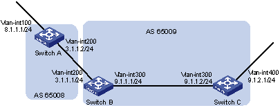
Figure 5-17 Network diagram for BGP and IGP synchronization
III. Configuration procedure
1) Configure IP addresses for interfaces (omitted)
2) Configure OSPF (omitted)
3) Configure the EBGP connection
# Configure Switch A.
<SwitchA> system-view
[SwitchA] bgp 65008
[SwitchA-bgp] router-id 1.1.1.1
[SwitchA-bgp] peer 3.1.1.1 as-number 65009
# Inject network 8.1.1.0/24 to the BGP routing table.
[SwitchA-bgp] network 8.1.1.0 24
[SwitchA-bgp] quit
# Configure Switch B.
<SwitchB> system-view
[SwitchB] bgp 65009
[SwitchB-bgp] peer 3.1.1.2 as-number 65008
[SwitchB-bgp] quit
4) Configure BGP and IGP synchronization
# Configure BGP to redistribute routes from OSPF on Switch B.
[SwitchB] bgp 65009
[SwitchB-bgp] import-route ospf 1
[SwitchB-bgp] quit
# Display routing table information on Switch A.
[SwitchA] display bgp routing-table
Total Number of Routes: 3
BGP Local router ID is 1.1.1.1
Status codes: * - valid, > - best, d - damped,
h - history, i - internal, s - suppressed, S - Stale
Origin : i - IGP, e - EGP, ? - incomplete
Network NextHop MED LocPrf PrefVal Path/Ogn
*> 8.1.1.0/24 0.0.0.0 0 0 i
*> 9.1.1.0/24 3.1.1.1 0 0 65009?
*> 9.1.2.0/24 3.1.1.1 2 0 65009?
# Configure OSPF to redistribute routes from BGP on Switch B.
[SwitchB] ospf
[SwitchB-ospf-1] import-route bgp
[SwitchB-ospf-1] quit
# Display routing table information on Switch C.
<SwitchC> display ip routing-table
Routing Tables: Public
Destinations : 7 Routes : 7
Destination/Mask Proto Pre Cost NextHop Interface
8.1.1.0/24 O_ASE 150 1 9.1.1.1 Vlan300
9.1.1.0/24 Direct 0 0 9.1.1.2 Vlan300
9.1.1.2/32 Direct 0 0 127.0.0.1 InLoop0
9.1.2.0/24 Direct 0 0 9.1.2.1 Vlan400
9.1.2.1/32 Direct 0 0 127.0.0.1 InLoop0
127.0.0.0/8 Direct 0 0 127.0.0.1 InLoop0
127.0.0.1/32 Direct 0 0 127.0.0.1 InLoop0
5) Configure route automatic summarization
# Configure route automatic summarization on Switch B.
[SwitchB] bgp 65009
[SwitchB-bgp] summary automatic
# Display BGP routing table information on Switch A.
[SwitchA] display bgp routing-table
Total Number of Routes: 2
BGP Local router ID is 1.1.1.1
Status codes: * - valid, > - best, d - damped,
h - history, i - internal, s - suppressed, S - Stale
Origin : i - IGP, e - EGP, ? - incomplete
Network NextHop MED LocPrf PrefVal Path/Ogn
*> 8.1.1.0/24 0.0.0.0 0 0 i
*> 9.0.0.0 3.1.1.1 0 65009?
# Use ping for verification.
[SwitchA] ping -a 8.1.1.1 9.1.2.1
PING 9.1.2.1: 56 data bytes, press CTRL_C to break
Reply from 9.1.2.1: bytes=56 Sequence=1 ttl=254 time=15 ms
Reply from 9.1.2.1: bytes=56 Sequence=2 ttl=254 time=31 ms
Reply from 9.1.2.1: bytes=56 Sequence=3 ttl=254 time=47 ms
Reply from 9.1.2.1: bytes=56 Sequence=4 ttl=254 time=46 ms
Reply from 9.1.2.1: bytes=56 Sequence=5 ttl=254 time=47 ms
--- 9.1.2.1 ping statistics ---
5 packet(s) transmitted
5 packet(s) received
0.00% packet loss
round-trip min/avg/max = 15/37/47 ms
5.10.3 BGP Load Balancing and MED Attribute Configuration
I. Network requirements
l Configure BGP on all switches; Switch A is in AS65008, and Switch B and C in AS65009.
l Between Switch A and B, and between Switch A and C are EBGP connections, and an IBGP connection is between Switch B and C.
II. Network diagram
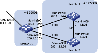
Figure 5-18 Network diagram for BGP load balancing configuration
III. Configuration procedure
1) Configure IP addresses for interfaces (omitted)
2) Configure BGP connections
# Configure Switch A.
<SwitchA> system-view
[SwitchA] bgp 65008
[SwitchA-bgp] router-id 1.1.1.1
[SwitchA-bgp] peer 200.1.1.1 as-number 65009
[SwitchA-bgp] peer 200.1.2.1 as-number 65009
# Inject route 8.0.0.0/8 to BGP routing table.
[SwitchA-bgp] network 8.0.0.0 255.0.0.0
[SwitchA-bgp] quit
# Configure Switch B.
<SwitchB> system-view
[SwitchB] bgp 65009
[SwitchB-bgp] router-id 2.2.2.2
[SwitchB-bgp] peer 200.1.1.2 as-number 65008
[SwitchB-bgp] peer 9.1.1.2 as-number 65009
[SwitchB-bgp] network 9.1.1.0 255.255.255.0
[SwitchB-bgp] quit
# Configure Switch C.
<SwitchC> system-view
[SwitchC] bgp 65009
[SwitchC-bgp] router-id 3.3.3.3
[SwitchC-bgp] peer 200.1.2.2 as-number 65008
[SwitchC-bgp] peer 9.1.1.1 as-number 65009
[SwitchC-bgp] network 9.1.1.0 255.255.255.0
[SwitchC-bgp] quit
# Display the routing table on Switch A.
[SwitchA] display bgp routing-table
Total Number of Routes: 3
BGP Local router ID is 1.1.1.1
Status codes: * - valid, > - best, d - damped,
h - history, i - internal, s - suppressed, S - Stale
Origin : i - IGP, e - EGP, ? - incomplete
Network NextHop MED LocPrf PrefVal Path/Ogn
*> 8.0.0.0 0.0.0.0 0 0 i
*> 9.1.1.0/24 200.1.1.1 0 0 65009i
* 200.1.2.1 0 0 65009i
Two routes to 9.1.1.0/24 are available, and the one with the next hop being 200.1.1.1 is the optimal because the ID of Switch B is smaller.
3) Configure loading balancing
# Configure Switch A.
[SwitchA] bgp 65008
[SwitchA-bgp] balance 2
[SwitchA-bgp] quit
# Display the routing table on Switch A.
[SwitchA] display bgp routing-table
Total Number of Routes: 3
BGP Local router ID is 1.1.1.1
Status codes: * - valid, > - best, d - damped,
h - history, i - internal, s - suppressed, S - Stale
Origin : i - IGP, e - EGP, ? - incomplete
Network NextHop MED LocPrf PrefVal Path/Ogn
*> 8.0.0.0 0.0.0.0 0 0 i
*> 9.1.1.0/24 200.1.1.1 0 0 65009i
*> 200.1.2.1 0 0 65009i
The route 9.1.1.0/24 has two next hops 200.1.1.1 and 200.1.2.1, and both are the optimal.
4) Configure MED
# Configure the default MED of Switch B.
[SwitchB] bgp 65009
[SwitchB-bgp] default med 100
# Display the routing table on Switch A.
[SwitchA] display bgp routing-table
Total Number of Routes: 3
BGP Local router ID is 1.1.1.1
Status codes: * - valid, > - best, d - damped,
h - history, i - internal, s - suppressed, S - Stale
Origin : i - IGP, e - EGP, ? - incomplete
Network NextHop MED LocPrf PrefVal Path/Ogn
*> 8.0.0.0 0.0.0.0 0 0 i
*> 9.1.1.0/24 200.1.2.1 0 0 65009i
* 200.1.1.1 100 0 65009i
From the above information, you can find the route with the next hop 200.1.2.1 is the best route, because its MED (0) is smaller than the MED (100) of the other route with the next hop 200.1.1.1 (Switch B).
5.10.4 BGP Community Configuration
I. Network requirements
Switch B establishes EBGP connections with Switch A and C. Configure No_Export community attribute on Switch A to make routes from AS 10 not advertised by AS 20 to any other AS.
II. Network diagram
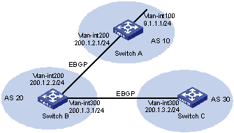
Figure 5-19 Network diagram for BGP community configuration
III. Configuration procedure
1) Configure IP addresses for interfaces (omitted)
2) Configure EBGP
# Configure Switch A.
<SwitchA> system-view
[SwitchA] bgp 10
[SwitchA-bgp] router-id 1.1.1.1
[SwitchA-bgp] peer 200.1.2.2 as-number 20
[SwitchA-bgp] network 9.1.1.0 255.255.255.0
[SwitchA-bgp] quit
# Configure Switch B.
<SwitchB> system-view
[SwitchB] bgp 20
[SwitchB-bgp] router-id 2.2.2.2
[SwitchB-bgp] peer 200.1.2.1 as-number 10
[SwitchB-bgp] peer 200.1.3.2 as-number 30
[SwitchB-bgp] quit
# Configure Switch C.
<SwitchC> system-view
[SwitchC] bgp 30
[SwitchC-bgp] router-id 3.3.3.3
[SwitchC-bgp] peer 200.1.3.1 as-number 20
[SwitchC-bgp] quit
# Display the BGP routing table on Switch B.
[SwitchB] display bgp routing-table 9.1.1.0
BGP local router ID : 2.2.2.2
Local AS number : 20
Paths: 1 available, 1 best
BGP routing table entry information of 9.1.1.0/24:
From : 200.1.2.1 (1.1.1.1)
Original nexthop: 200.1.2.1
AS-path : 10
Origin : igp
Attribute value : MED 0, pref-val 0, pre 255
State : valid, external, best,
Advertised to such 1 peers:
200.1.3.2
Switch B advertised routes to Switch C in AS30.
# Display the routing table on Switch C.
[SwitchC] display bgp routing-table
Total Number of Routes: 1
BGP Local router ID is 3.3.3.3
Status codes: * - valid, > - best, d - damped,
h - history, i - internal, s - suppressed, S - Stale
Origin : i - IGP, e - EGP, ? - incomplete
Network NextHop MED LocPrf PrefVal Path/Ogn
*> 9.1.1.0/24 200.1.3.1 0 20 10i
Switch C learned route 9.1.1.0/24 from Switch B.
3) Configure BGP community
# Configure a routing policy.
[SwitchA] route-policy comm_policy permit node 0
[SwitchA-route-policy] apply community no-export
[SwitchA-route-policy] quit
# Apply the routing policy.
[SwitchA] bgp 10
[SwitchA-bgp] peer 200.1.2.2 route-policy comm_policy export
[SwitchA-bgp] peer 200.1.2.2 advertise-community
# Display the routing table on Switch B.
[SwitchB] display bgp routing-table 9.1.1.0
BGP local router ID : 2.2.2.2
Local AS number : 20
Paths: 1 available, 1 best
BGP routing table entry information of 9.1.1.0/24:
From : 200.1.2.1 (1.1.1.1)
Original nexthop: 200.1.2.1
Community : No-Export
AS-path : 10
Origin : igp
Attribute value : MED 0, pref-val 0, pre 255
State : valid, external, best,
Not advertised to any peers yet
The route 9.1.1.0/24 is not available in the routing table of Switch C.
5.10.5 BGP Route Reflector Configuration
I. Network requirements
In the following figure, all switches run BGP.
l Between Switch A and Switch B is an EBGP connection, between Switch C and Switch B, and between Switch C and Switch D are IBGP connections.
l Switch C is a route reflector with clients Switch B and D.
l Switch D can learn route 1.0.0.0/8 from Switch C.
II. Network diagram
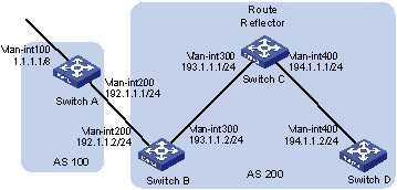
Figure 5-20 Network diagram for BGP route reflector configuration
III. Configuration procedure
1) Configure IP addresses for interfaces (omitted)
2) Configure BGP connections
# Configure Switch A.
<SwitchA> system-view
[SwitchA] bgp 100
[SwitchA-bgp] router-id 1.1.1.1
[SwitchA-bgp] peer 192.1.1.2 as-number 200
# Inject network 1.0.0.0/8 to the BGP routing table.
[SwitchA-bgp] network 1.0.0.0
[SwitchA-bgp] quit
# Configure Switch B.
<SwitchB> system-view
[SwitchB] bgp 200
[SwitchB-bgp] router-id 2.2.2.2
[SwitchB-bgp] peer 192.1.1.1 as-number 100
[SwitchB-bgp] peer 193.1.1.1 as-number 200
[SwitchB-bgp] peer 193.1.1.1 next-hop-local
[SwitchB-bgp] quit
# Configure Switch C.
<SwitchC> system-view
[SwitchC] bgp 200
[SwitchC-bgp] router-id 3.3.3.3
[SwitchC-bgp] peer 193.1.1.2 as-number 200
[SwitchC-bgp] peer 194.1.1.2 as-number 200
[SwitchC-bgp] quit
# Configure Switch D.
<SwitchD> system-view
[SwitchD] bgp 200
[SwitchD-bgp] router-id 4.4.4.4
[SwitchD-bgp] peer 194.1.1.1 as-number 200
[SwitchD-bgp] quit
3) Configure the route reflector
# Configure Switch C.
[SwitchC] bgp 200
[SwitchC-bgp] peer 193.1.1.2 reflect-client
[SwitchC-bgp] peer 194.1.1.2 reflect-client
[SwitchC-bgp] quit
4) Verify the above configuration
# Display the BGP routing table on Switch B.
[SwitchB] display bgp routing-table
Total Number of Routes: 1
BGP Local router ID is 2.2.2.2
Status codes: * - valid, > - best, d - damped,
h - history, i - internal, s - suppressed, S - Stale
Origin : i - IGP, e - EGP, ? - incomplete
Network NextHop MED LocPrf PrefVal Path/Ogn
*> 1.0.0.0 192.1.1.1 0 0 100i
# Display the BGP routing table on Switch D.
[SwitchD] display bgp routing-table
Total Number of Routes: 1
BGP Local router ID is 4.4.4.4
Status codes: * - valid, > - best, d - damped,
h - history, i - internal, s - suppressed, S - Stale
Origin : i - IGP, e - EGP, ? - incomplete
Network NextHop MED LocPrf PrefVal Path/Ogn
i 1.0.0.0 193.1.1.2 0 100 0 100i
Switch D learned route 1.0.0.0/8 from Switch C.
5.10.6 BGP Confederation Configuration
I. Network requirements
To reduce IBGP connections in AS 200, split it into three sub-ASs, AS65001, AS65002 and AS65003. Switches in AS65001 are fully meshed.
II. Network diagram
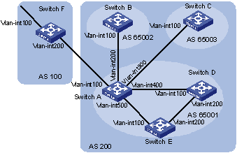
|
Device |
Interface |
IP address |
Device |
Interface |
IP address |
|
Switch A |
Vlan-int100 |
200.1.1.1/24 |
Switch D |
Vlan-int100 |
10.1.3.2/24 |
|
|
Vlan-int200 |
10.1.1.1/24 |
|
Vlan-int200 |
10.1.5.1/24 |
|
|
Vlan-int300 |
10.1.2.1/24 |
Switch E |
Vlan-int100 |
10.1.4.2/24 |
|
|
Vlan-int400 |
10.1.3.1/24 |
|
Vlan-int200 |
10.1.5.2/24 |
|
|
Vlan-int500 |
10.1.4.1/24 |
Switch F |
Vlan-int100 |
9.1.1.1/24 |
|
Switch B |
Vlan-int100 |
10.1.1.2/24 |
|
Vlan-int200 |
200.1.1.2/24 |
|
Switch C |
Vlan-int100 |
10.1.2.2/24 |
|
|
|
Figure 5-21 Network diagram for BGP confederation configuration (on switches)
III. Configuration procedure
1) Configure IP addresses for interfaces (omitted)
2) Configure BGP confederation
# Configure Switch A.
<SwitchA> system-view
[SwitchA] bgp 65001
[SwitchA-bgp] router-id 1.1.1.1
[SwitchA-bgp] confederation id 200
[SwitchA-bgp] confederation peer-as 65002 65003
[SwitchA-bgp] peer 10.1.1.2 as-number 65002
[SwitchA-bgp] peer 10.1.1.2 next-hop-local
[SwitchA-bgp] peer 10.1.2.2 as-number 65003
[SwitchA-bgp] peer 10.1.2.2 next-hop-local
[SwitchA-bgp] quit
# Configure Switch B.
<SwitchB> system-view
[SwitchB] bgp 65002
[SwitchB-bgp] router-id 2.2.2.2
[SwitchB-bgp] confederation id 200
[SwitchB-bgp] confederation peer-as 65001 65003
[SwitchB-bgp] peer 10.1.1.1 as-number 65001
[SwitchB-bgp] quit
# Configure Switch C.
<SwitchC> system-view
[SwitchC] bgp 65003
[SwitchC-bgp] router-id 3.3.3.3
[SwitchC-bgp] confederation id 200
[SwitchC-bgp] confederation peer-as 65001 65002
[SwitchC-bgp] peer 10.1.2.1 as-number 65001
[SwitchC-bgp] quit
3) Configure IBGP connections in AS65001.
# Configure Switch A.
[SwitchA] bgp 65001
[SwitchA-bgp] peer 10.1.3.2 as-number 65001
[SwitchA-bgp] peer 10.1.3.2 next-hop-local
[SwitchA-bgp] peer 10.1.4.2 as-number 65001
[SwitchA-bgp] peer 10.1.4.2 next-hop-local
[SwitchA-bgp] quit
# Configure Switch D.
<SwitchD> system-view
[SwitchD] bgp 65001
[SwitchD-bgp] router-id 4.4.4.4
[SwitchD-bgp] confederation id 200
[SwitchD-bgp] peer 10.1.3.1 as-number 65001
[SwitchD-bgp] peer 10.1.5.2 as-number 65001
[SwitchD-bgp] quit
# Configure Switch E.
<SwitchE> system-view
[SwitchE] bgp 65001
[SwitchE-bgp] router-id 5.5.5.5
[SwitchE-bgp] confederation id 200
[SwitchE-bgp] peer 10.1.4.1 as-number 65001
[SwitchE-bgp] peer 10.1.5.1 as-number 65001
[SwitchE-bgp] quit
4) Configure the EBGP connection between AS100 and AS200.
# Configure Switch A.
[SwitchA] bgp 65001
[SwitchA-bgp] peer 200.1.1.2 as-number 100
[SwitchA-bgp] quit
# Configure Switch F.
<SwitchF> system-view
[SwitchF] bgp 100
[SwitchF-bgp] router-id 6.6.6.6
[SwitchF-bgp] peer 200.1.1.1 as-number 200
[SwitchF-bgp] network 9.1.1.0 255.255.255.0
[SwitchF-bgp] quit
5) Verify above configuration
# Display the routing table on Switch B.
[SwitchB] display bgp routing-table
Total Number of Routes: 1
BGP Local router ID is 2.2.2.2
Status codes: * - valid, > - best, d - damped,
h - history, i - internal, s - suppressed, S - Stale
Origin : i - IGP, e - EGP, ? - incomplete
Network NextHop MED LocPrf PrefVal Path/Ogn
*>i 9.1.1.0/24 10.1.1.1 0 100 0 (65001) 100i
[SwitchB] display bgp routing-table 9.1.1.0
BGP local router ID : 2.2.2.2
Local AS number : 65002
Paths: 1 available, 1 best
BGP routing table entry information of 9.1.1.0/24:
From : 10.1.1.1 (1.1.1.1)
Relay Nexthop : 0.0.0.0
Original nexthop: 10.1.1.1
AS-path : (65001) 100
Origin : igp
Attribute value : MED 0, localpref 100, pref-val 0, pre 255
State : valid, external-confed, best,
Not advertised to any peers yet
# Display the BGP routing table on Switch D.
[SwitchD] display bgp routing-table
Total Number of Routes: 1
BGP Local router ID is 4.4.4.4
Status codes: * - valid, > - best, d - damped,
h - history, i - internal, s - suppressed, S - Stale
Origin : i - IGP, e - EGP, ? - incomplete
Network NextHop MED LocPrf PrefVal Path/Ogn
*>i 9.1.1.0/24 10.1.3.1 0 100 0 100i
[SwitchD] display bgp routing-table 9.1.1.0
BGP local router ID : 4.4.4.4
Local AS number : 65001
Paths: 1 available, 1 best
BGP routing table entry information of 9.1.1.0/24:
From : 10.1.3.1 (1.1.1.1)
Relay Nexthop : 0.0.0.0
Original nexthop: 10.1.3.1
AS-path : 100
Origin : igp
Attribute value : MED 0, localpref 100, pref-val 0, pre 255
State : valid, internal, best,
Not advertised to any peers yet
5.10.7 BGP Path Selection Configuration
I. Network requirements
l In the figure below, all switches run BGP. Between Switch A and Switch B, and between Switch A and Switch C are EBGP connections. Between Switch B and Switch D, and between Switch D and Switch C are IBGP connections.
l OSPF is the IGP protocol in AS 200.
l Configure routing policies, making Switch D use the route 1.0.0.0/8 from Switch C as the optimal.
II. Network diagram
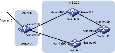
|
Device |
Interface |
IP address |
Device |
Interface |
IP address |
|
Switch A |
Vlan-int101 |
1.0.0.1/8 |
Switch D |
Vlan-int400 |
195.1.1.1/24 |
|
|
Vlan-int100 |
192.1.1.1/24 |
|
Vlan-int300 |
194.1.1.1/24 |
|
|
Vlan-int200 |
193.1.1.1/24 |
Switch C |
Vlan-int400 |
195.1.1.2/24 |
|
Switch B |
Vlan-int100 |
192.1.1.2/24 |
|
Vlan-int200 |
193.1.1.2/24 |
|
|
Vlan-int300 |
194.1.1.2/24 |
|
|
|
Figure 5-22 Network diagram for BGP path selection configuration
III. Configuration procedure
1) Configure IP addresses for interfaces (omitted).
2) Configure OSPF on Switch B, C, and D.
# Configure Switch B.
<SwitchB> system-view
[SwitchB] ospf
[SwitchB-ospf] area 0
[SwitchB-ospf-1-area-0.0.0.0] network 192.1.1.0 0.0.0.255
[SwitchB-ospf-1-area-0.0.0.0] network 194.1.1.0 0.0.0.255
[SwitchB-ospf-1-area-0.0.0.0] quit
[SwitchB-ospf-1] quit
# Configure Switch C.
<SwitchC> system-view
[SwitchC] ospf
[SwitchC-ospf] area 0
[SwitchC-ospf-1-area-0.0.0.0] network 193.1.1.0 0.0.0.255
[SwitchC-ospf-1-area-0.0.0.0] network 195.1.1.0 0.0.0.255
[SwitchC-ospf-1-area-0.0.0.0] quit
[SwitchC-ospf-1] quit
# Configure Switch D.
<SwitchD> system-view
[SwitchD] ospf
[SwitchD-ospf] area 0
[SwitchD-ospf-1-area-0.0.0.0] network 194.1.1.0 0.0.0.255
[SwitchD-ospf-1-area-0.0.0.0] network 195.1.1.0 0.0.0.255
[SwitchD-ospf-1-area-0.0.0.0] quit
[SwitchD-ospf-1] quit
3) Configure BGP connections
# Configure Switch A.
<SwitchA> system-view
[SwitchA] bgp 100
[SwitchA-bgp] peer 192.1.1.2 as-number 200
[SwitchA-bgp] peer 193.1.1.2 as-number 200
# Inject network 1.0.0.0/8 to the BGP routing table on Switch A.
[SwitchA-bgp] network 1.0.0.0 8
[SwitchA-bgp] quit
# Configure Switch B.
[SwitchB] bgp 200
[SwitchB-bgp] peer 192.1.1.1 as-number 100
[SwitchB-bgp] peer 194.1.1.1 as-number 200
[SwitchB-bgp] quit
# Configure Switch C.
[SwitchC] bgp 200
[SwitchC-bgp] peer 193.1.1.1 as-number 100
[SwitchC-bgp] peer 195.1.1.1 as-number 200
[SwitchC-bgp] quit
# Configure Switch D.
[SwitchD] bgp 200
[SwitchD-bgp] peer 194.1.1.2 as-number 200
[SwitchD-bgp] peer 195.1.1.2 as-number 200
[SwitchD-bgp] quit
4) Configure attributes for route 1.0.0.0/8, making Switch D give priority to the route learned from Switch C.
l Configure a higher MED value for the route 1.0.0.0/8 advertised from Switch A to peer 192.1.1.2.
# Define an ACL numbered 2000 to permit route 1.0.0.0/8.
[SwitchA] acl number 2000
[SwitchA-acl-basic-2000] rule permit source 1.0.0.0 0.255.255.255
[SwitchA-acl-basic-2000] quit
# Define two routing policies, apply_med_50, which sets the MED for route 1.0.0.0/8 to 50, and apply_med_100, which sets the MED for route 1.0.0.0/8 to 100.
[SwitchA] route-policy apply_med_50 permit node 10
[SwitchA-route-policy] if-match acl 2000
[SwitchA-route-policy] apply cost 50
[SwitchA-route-policy] quit
[SwitchA] route-policy apply_med_100 permit node 10
[SwitchA-route-policy] if-match acl 2000
[SwitchA-route-policy] apply cost 100
[SwitchA-route-policy] quit
# Apply routing policy apply_med_50 to the route advertised to peer 193.1.1.2 (Switch C), and apply_med_100 to the route advertised to peer 192.1.1.2 (Switch B).
[SwitchA] bgp 100
[SwitchA-bgp] peer 193.1.1.2 route-policy apply_med_50 export
[SwitchA-bgp] peer 192.1.1.2 route-policy apply_med_100 export
[SwitchA-bgp] quit
# Display the BGP routing table on Switch D.
[SwitchD] display bgp routing-table
Total Number of Routes: 2
BGP Local router ID is 194.1.1.1
Status codes: * - valid, > - best, d - damped,
h - history, i - internal, s - suppressed, S - Stale
Origin : i - IGP, e - EGP, ? - incomplete
Network NextHop MED LocPrf PrefVal Path/Ogn
*>i 1.0.0.0 193.1.1.1 50 100 0 100i
* i 192.1.1.1 100 100 0 100i
You can find route 1.0.0.0/8 is the optimal.
l Configure different local preferences on Switch B and C for route 1.0.0.0/8, making Switch D give priority to the route from Switch C.
# Define an ACL numbered 2000 on Router C, permitting route 1.0.0.0/8.
[SwitchC] acl number 2000
[SwitchC-acl-basic-2000] rule permit source 1.0.0.0 0.255.255.255
[SwitchC-acl-basic-2000] quit
# Configure a routing policy named localpref on Switch C, setting the local preference of route 1.0.0.0/8 to 200 (the default is 100).
[SwitchC] route-policy localpref permit node 10
[SwitchC-route-policy] if-match acl 2000
[SwitchC-route-policy] apply local-preference 200
[SwitchC-route-policy] quit
# Apply routing policy localpref to routes from peer 193.1.1.1.
[SwitchC] bgp 200
[SwitchC-bgp] peer 193.1.1.1 route-policy localpref import
[SwitchC-bgp] quit
# Display the routing table on Switch D.
[SwitchD] display bgp routing-table
Total Number of Routes: 2
BGP Local router ID is 194.1.1.1
Status codes: * - valid, > - best, d - damped,
h - history, i - internal, s - suppressed, S - Stale
Origin : i - IGP, e - EGP, ? - incomplete
Network NextHop MED LocPrf PrefVal Path/Ogn
*>i 1.0.0.0 193.1.1.1 0 200 0 100i
* i 192.1.1.1 0 100 0 100i
You can find route 1.0.0.0/8 from Switch D to Switch C is the optimal.
5.11 Troubleshooting BGP
5.11.1 No BGP Peer Relationship Established
I. Symptom
Display BGP peer information using the display bgp peer command. The state of the connection to a peer cannot become established.
II. Analysis
To become BGP peers, any two routers need to establish a TCP session using port 179 and exchange open messages successfully.
III. Solution
1) Use the display current-configuration command to verify the peer’s AS number.
2) Use the display bgp peer command to verify the peer’s IP address.
3) If the loopback interface is used, check whether the peer connect-interface command is configured.
4) If the peer is a non-direct EBGP peer, check whether the peer ebgp-max-hop command is configured.
5) Check whether a route to the peer is available in the routing table.
6) Use the ping command to check connectivity.
7) Use the display tcp status command to check the TCP connection.
8) Check whether an ACL disabling TCP port 179 is configured.
Chapter 6 Routing Policy Configuration
A routing policy is used on a router for route inspection, filtering, attributes modification when routes are received, advertised, or redistributed.
When configuring routing policy, go to these sections for information you are interested in:
l Introduction to Routing Policy
l Routing Policy Configuration Task List
l Configuring a Routing Policy
l Displaying and Maintaining the Routing Policy
l Routing Policy Configuration Example
l Troubleshooting Routing Policy Configuration
Routing policy described in this chapter includes both IPv4 routing policy and IPv6 routing policy. Configurations of the two are similar, and differences are described in related sections.
6.1 Introduction to Routing Policy
6.1.1 Routing Policy and Policy Routing
A routing policy is used on the router for route inspection, filtering, attributes modifying when routes are received, advertised, or redistributed.
Policy routing is a routing mechanism based on the user-defined policies.
This chapter describes only routing policy configuration and usage, refer to IP Unicast Policy Routing Configuration in the IP Services Volume for policy routing information.
When distributing or receiving routing information, a router can use a routing policy to filter routing information. For example, a router receives or advertises only routing information that matches the criteria of a routing policy; a routing protocol redistributes routes from another protocol only routes matching the criteria of a routing policy and modifies some attributes of these routes to satisfy its needs using the routing policy.
To implement a routing policy, you need to define a set of match criteria according to attributes in routing information, such as destination address, advertising router’s address and so on. The match criteria can be set beforehand and then apply them to a routing policy for route distribution, reception and redistribution.
6.1.2 Filters
Routing protocols can use six filters: ACL, IP prefix list, AS path ACL, community list, extended community list and routing policy.
I. ACL
ACL involves IPv4 ACL and IPv6 ACL. When defining an ACL, you can specify IP addresses and prefixes to match destinations or next hops of routing information.
For ACL configuration, refer to ACL configuration in the Security Volume.
II. IP prefix list
IP prefix list plays a role similar to ACL, but it is more flexible than ACL and easier to understand. When an IP prefix list is applied to filtering routing information, its matching object is the destination address of routing information. Moreover, you can specify the gateway option to indicate that only routing information advertised by certain routers will be received.
An IP prefix list is identified by name. Each IP prefix list can comprise multiple items, and each item, which is identified by an index number, can specify a matching range in the network prefix format. The index number indicates the matching sequence of items in the IP prefix list.
During matching, the router compares the packet with the items in the ascending order. If one item is matched, the IP prefix list filter is passed, and the packet will not go to the next item.
III. AS-path
AS path is only applicable to BGP. There is an AS-path field in the BGP packet. An AS path list specifies matching conditions according to the AS-path field.
IV. Community list
Community list only applies to BGP. The BGP packet contains a community attribute field to identify a community. A community list specifies matching conditions based on the community attribute.
V. Extended community list
Extended community list (extcommunity-list) applies to BGP only. It involves two attributes: Route-Target extcommunity for VPN, Source of Origin extcommunity. An extcommunity-list specifies matching conditions according to the two attributes.
VI. Routing policy
A routing policy is used to match against some attributes in given routing information and modify the attributes of the information if match conditions are satisfied. It can reference the above mentioned filters to define its own match criteria.
A routing policy can comprise multiple nodes, which are in logic OR relationship. Each node is a match unit, and the system compares each node to a packet in the order of node sequence number. Once a node is matched, the routing policy is passed and the packet will not go through the next node.
Each node comprises a set of if-match and apply clauses. The if-match clauses define the match criteria. The matching objects are some attributes of routing information. The different if-match clauses on a node is in logical AND relationship. Only when the matching conditions specified by all the if-match clauses on the node are satisfied, can routing information pass the node. The apply clauses specify the actions to be performed after the node is passed, concerning the attribute settings for routing information.
6.1.3 Routing Policy Application
A routing policy is applied in two ways:
l When redistributing routes from other routing protocols, a routing protocol accepts only routes passing the routing policy.
l When receiving or advertising routing information, a routing protocol uses the routing policy to filter routing information.
6.2 Routing Policy Configuration Task List
Complete the following tasks to configure a routing policy:
|
Task |
|
6.3 Defining Filtering Lists
6.3.1 Prerequisites
Before configuring this task, you need to decide on:
l IP-prefix list name
l Matching address range
l Extcommunity list sequence number
6.3.2 Defining an IPv4 Prefix List
Identified by name, each IPv4 prefix list can comprise multiple items. Each item specifies a matching address range in the form of network prefix identified by index number.
During matching, the system compares the route to each item identified by index number in the ascending order. If one item matches, the route passes the IP-prefix list, without needing to match against the next item.
Follow these steps to define an IPv4 prefix list:
|
To do… |
Use the command… |
Remarks |
|
Enter system view |
system-view |
— |
|
Define an IPv4 prefix list |
ip ip-prefix ip-prefix-name [ index index-number ] { permit | deny } ip-address mask-length [ greater-equal min-mask-length ] [ less-equal max-mask-length ] |
Required Not defined by default |
& Note:
If all items are set to the deny mode, no routes can pass the IPv4 prefix list. Therefore, you need to define the permit 0.0.0.0 0 less-equal 32 item following multiple deny mode items to allow other IPv4 routing information to pass.
For example, the following configuration filters routes 10.1.0.0/16, 10.2.0.0/16 and 10.3.0.0/16, but allows other routes to pass.
<Sysname> system-view
[Sysname] ip ip-prefix abc index 10 deny 10.1.0.0 16
[Sysname] ip ip-prefix abc index 20 deny 10.2.0.0 16
[Sysname] ip ip-prefix abc index 30 deny 10.3.0.0 16
[Sysname] ip ip-prefix abc index 40 permit 0.0.0.0 0 less-equal 32
6.3.3 Defining an AS Path List
You can define multiple items for an AS path ACL that is identified by number. During matching, the relation between items is logical OR, that is, if the route matches one of these items, it passes the AS path ACL.
Follow these steps to define an AS path ACL:
|
To do… |
Use the command… |
Remarks |
|
Enter system view |
system-view |
— |
|
Define an AS path ACL |
ip as-path as-path-number { deny | permit } regular-expression |
Required Not defined by default |
6.3.4 Defining a Community List
You can define multiple items for a community list that is identified by number. During matching, the relation between items is logic OR, that is, if routing information matches one of these items, it passes the community list.
Follow these steps to define a community list:
|
To do… |
Use the command… |
Remarks |
|
|
Enter system view |
system-view |
— |
|
|
Define a community list |
Define a basic community list |
ip community-list basic-comm-list-num { deny | permit } [ community-number-list ] [ internet | no-advertise | no-export | no-export-subconfed ] * |
Required to define either; Not defined by default |
|
Define an advanced community list |
ip community-list adv-comm-list-num { deny | permit } regular-expression |
||
6.3.5 Defining an Extended Community List
You can define multiple items for an extended community list that is identified by number. During matching, the relation between items is logic OR, that is, if routing information matches one of these items, it passes the extended community list.
Follow these steps to define an extended community list:
|
To do… |
Use the command… |
Remarks |
|
Enter system view |
system-view |
— |
|
Define an extended community list |
ip extcommunity-list ext-comm-list-number { deny | permit } { rt route-target }&<1-16> |
Required Not defined by default |
6.4 Configuring a Routing Policy
A routing policy is used to filter routing information according to some attributes, and modify some attributes of the routing information that matches the routing policy. Match criteria can be configured using filters above mentioned.
A routing policy can comprise multiple nodes, each node contains:
l if-match clauses: Define the match criteria that routing information must satisfy. The matching objects are some attributes of routing information.
l apply clauses: Specify the actions performed after specified match criteria are satisfied, concerning attribute settings for passed routing information.
6.4.1 Prerequisites
Before configuring this task, you have completed:
l Filtering list configuration
l Routing protocol configuration
You also need to decide on:
l Name of the routing policy, node sequence numbers
l Match criteria
l Attributes to be modified
6.4.2 Creating a Routing Policy
Follow these steps to create a routing policy:
|
To do… |
Use the command… |
Remarks |
|
Enter system view |
system-view |
— |
|
Create a routing policy and enter its view |
route-policy route-policy-name { permit | deny } node node-number |
Required |
& Note:
l If a node has the permit keyword specified, routing information meeting the node’s conditions will be handled using the apply clauses of this node, without needing to match against the next node. If routing information does not meet the node’s conditions, it will go to the next node for a match.
l If a node is specified as deny, the apply clauses of the node will not be executed. When routing information matches all if-match clauses of the node, it can neither pass the node, nor go to the next node. If route information cannot match any if-match clause of the node, it will go to the next node for a match.
l When a routing policy is defined with more than one node, at least one node should be configured with the permit keyword. If the routing policy is used to filter routing information, routing information that does not meet any node’s conditions cannot pass the routing policy. If all nodes of the routing policy are set using the deny keyword, no routing information can pass it.
6.4.3 Defining if-match Clauses for the Routing Policy
Follow these steps to define if-match clauses for a route-policy:
|
To do… |
Use the command… |
Remarks |
|
|
Enter system view |
system-view |
— |
|
|
Enter routing policy view |
route-policy route-policy-name { permit | deny } node node-number |
— |
|
|
Define match criteria for IPv4 routes |
Match IPv4 routes having destinations specified in the ACL |
if-match acl acl-number |
Optional Not configured by default |
|
Match IPv4 routes having destinations specified in the IP prefix list |
if-match ip-prefix ip-prefix-name |
||
|
Match IPv4 routes having next hops or sources specified in the ACL or IP prefix list |
if-match ip { next-hop | route-source } { acl acl-number | ip-prefix ip-prefix-name } |
Optional Not configured by default |
|
|
Match routes having AS path attributes specified in the AS path list (s) |
if-match as-path as-path-number&<1-16> |
Optional Not configured by default |
|
|
Match routes having community attributes in the specified community list(s) |
if-match community { basic-community-list-number [ whole-match ] | adv-community-list-number }&<1-16> |
Optional Not configured by default |
|
|
Match routes having the specified cost |
if-match cost value |
Optional Not configured by default |
|
|
Match BGP routes having extended attributes contained in the extended community list(s) |
if-match extcommunity ext-comm-list-number&<1-16> |
Optional Not configured by default |
|
|
Match routes having specified outbound interface(s) |
if-match interface { interface-type interface-number }&<1-16> |
Optional Not configured by default |
|
|
Match routes having the specified route type |
if-match route-type { internal | external-type1 | external-type2 | external-type1or2 | is-is-level-1 | is-is-level-2 | nssa-external-type1 | nssa-external-type2 | nssa-external-type1or2 } * |
Optional Not configured by default |
|
|
Match RIP, OSPF, or IS-IS routes having the specified tag value |
if-match tag value |
Optional Not configured by default |
|
& Note:
l The if-match clauses of a route-policy are in logic AND relationship, namely, routing information has to satisfy all if-match clauses before being executed with apply clauses.
l You can specify no or multiple if-match clauses for a routing policy. If no if-match clause is specified, and the routing policy is in permit mode, all routing information can pass the node; if in deny mode, no routing information can pass.
l A routing policy should use a non VPN ACL for filtering.
6.4.4 Defining apply Clauses for the Routing Policy
Follow these steps to define apply clauses for a route-policy:
|
To do… |
Use the command… |
Remarks |
|
Enter system view |
system-view |
— |
|
Create a routing policy and enter its view |
route-policy route-policy-name { permit | deny } node node-number |
Required Not created by default |
|
Set AS_Path attribute for BGP routes |
Optional Not set by default |
|
|
Specify a community list according to which to delete community attributes of BGP routing information |
apply comm-list comm-list-number delete |
Optional Not configured by default |
|
Set community attribute for BGP routes |
apply community { none | additive | { community-number&<1-16> | aa:nn&<1-16> | internet | no-export-subconfed | no-export | no-advertise } * [ additive ] } |
Optional Not set by default |
|
Set a cost for routes |
apply cost [ + | - ] value |
Optional Not set by default |
|
Set a cost type for routes |
apply cost-type [ external | internal | type-1 | type-2 ] |
Optional Not set by default |
|
Set the extended community attribute for BGP routes |
apply extcommunity { rt { as-number:nn | ip-address:nn } }&<1-16> [ additive ] |
Optional Not set by default |
|
Set a next hop for IPv4 routes |
apply ip-address next-hop ip-address |
Optional Not configured by default |
|
Redistribute routes to a specified ISIS level |
apply isis { level-1 | level-1-2 | level-2 } |
Optional Not configured by default |
|
Set a local preference for BGP routes |
apply local-preference preference |
Optional Not set by default |
|
Set an origin attribute for BGP routes |
apply origin { igp | egp as-number | incomplete } |
Optional Not set by default |
|
Set a preference for the matched routing protocol |
apply preference preference |
Optional Not set by default |
|
Set a preferred value for BGP routes |
apply preferred-value preferred-value |
Optional Not set by default |
|
Set a tag value for RIP, OSPF or IS-IS routes |
apply tag value |
Optional Not set by default |
& Note:
The apply ip-address next-hop command does not apply to redistributed IPv4 routes.
6.5 Displaying and Maintaining the Routing Policy
|
To do… |
Use the command… |
Remarks |
|
Display BGP AS path ACL information |
display ip as-path [ as-path-number ] |
Available in any view |
|
Display BGP community list information |
display ip community-list [ basic-community-list-number | adv-community-list-number ] |
|
|
Display BGP extended community list information |
display ip extcommunity-list [ ext-comm-list-number ] |
|
|
Display IPv4 prefix list statistics |
display ip ip-prefix [ ip-prefix-name ] |
|
|
Display routing policy information |
display route-policy [ route-policy-name ] |
|
|
Clear IPv4 prefix list statistics |
reset ip ip-prefix [ ip-prefix-name ] |
Available in user view |
6.6 Routing Policy Configuration Example
6.6.1 Applying Routing Policy When Redistributing IPv4 Routes
I. Network Requirements
l Switch B exchanges routing information with Switch A via OSPF, with Switch C via IS-IS.
l On Switch B, configure route redistribution from IS-IS to OSPF and apply a routing policy to set attributes of redistributed routes, setting the cost of route 172.17.1.0/24 to 100, tag of route 172.17.2.0/24 to 20.
II. Network diagram
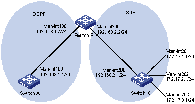
Figure 6-1 Network diagram for routing policy application to route redistribution
III. Configuration procedure
1) Specify IP addresses for interfaces (omitted).
2) Configure IS-IS
# Configure Switch C.
<SwitchC> system-view
[SwitchC] isis
[SwitchC-isis-1] is-level level-2
[SwitchC-isis-1] network-entity 10.0000.0000.0001.00
[SwitchC-isis-1] quit
[SwitchC] interface vlan-interface 200
[SwitchC-Vlan-interface200] isis enable
[SwitchC-Vlan-interface200] quit
[SwitchC] interface vlan-interface 201
[SwitchC-Vlan-interface201] isis enable
[SwitchC-Vlan-interface201] quit
[SwitchC] interface vlan-interface 202
[SwitchC-Vlan-interface202] isis enable
[SwitchC-Vlan-interface202] quit
[SwitchC] interface vlan-interface 203
[SwitchC-Vlan-interface203] isis enable
[SwitchC-Vlan-interface203] quit
# Configure Switch B.
<SwitchB> system-view
[SwitchB] isis
[SwitchB-isis-1] is-level level-2
[SwitchB-isis-1] network-entity 10.0000.0000.0002.00
[SwitchB-isis-1] quit
[SwitchB] interface vlan-interface 200
[SwitchB-Vlan-interface200] isis enable
[SwitchB-Vlan-interface200] quit
3) Configure OSPF and route redistribution
# Configure Switch A: enable OSPF.
<SwitchA> system-view
[SwitchA] ospf
[SwitchA-ospf-1] area 0
[SwitchA-ospf-1-area-0.0.0.0] network 192.168.1.0 0.0.0.255
[SwitchA-ospf-1-area-0.0.0.0] quit
[SwitchA-ospf-1] quit
# Configure Switch B: enable OSPF and redistribute routes from IS-IS.
[SwitchB] ospf
[SwitchB-ospf-1] area 0
[SwitchB-ospf-1-area-0.0.0.0] network 192.168.1.0 0.0.0.255
[SwitchB-ospf-1-area-0.0.0.0] quit
[SwitchB-ospf-1] import-route isis 1
[SwitchB-ospf-1] quit
# Display OSPF routing table on Switch A to view redistributed routes.
[SwitchA] display ospf routing
OSPF Process 1 with Router ID 192.168.1.1
Routing Tables
Routing for Network
Destination Cost Type NextHop AdvRouter Area
192.168.1.0/24 1562 Stub 192.168.1.1 192.168.1.1 0.0.0.0
Routing for ASEs
Destination Cost Type Tag NextHop AdvRouter
172.17.1.0/24 1 Type2 1 192.168.1.2 192.168.2.2
172.17.2.0/24 1 Type2 1 192.168.1.2 192.168.2.2
172.17.3.0/24 1 Type2 1 192.168.1.2 192.168.2.2
192.168.2.0/24 1 Type2 1 192.168.1.2 192.168.2.2
Total Nets: 5
Intra Area: 1 Inter Area: 0 ASE: 4 NSSA: 0
4) Configure filtering lists
# Configure an ACL with the number of 2002, letting pass route 172.17.2.0/24.
[SwitchB] acl number 2002
[SwitchB-acl-basic-2002] rule permit source 172.17.2.0 0.0.0.255
[SwitchB-acl-basic-2002] quit
# Configure an IP prefix list named prefix-a, letting pass route 172.17.1.0/24.
[SwitchB] ip ip-prefix prefix-a index 10 permit 172.17.1.0 24
5) Configure a routing policy.
[SwitchB] route-policy isis2ospf permit node 10
[SwitchB-route-policy] if-match ip-prefix prefix-a
[SwitchB-route-policy] apply cost 100
[SwitchB-route-policy] quit
[SwitchB] route-policy isis2ospf permit node 20
[SwitchB-route-policy] if-match acl 2002
[SwitchB-route-policy] apply tag 20
[SwitchB-route-policy] quit
[SwitchB] route-policy isis2ospf permit node 30
[SwitchB-route-policy] quit
6) Apply the routing policy to route redistribution.
# Configure Switch B: apply the routing policy when redistributing routes.
[SwitchB] ospf
[SwitchB-ospf-1] import-route isis 1 route-policy isis2ospf
[SwitchB-ospf-1] quit
# Display the OSPF routing table on Switch A. You can find the cost of route 172.17.1.0/24 is 100, tag of route 172.17.1.0/24 is 20, and other external routes have no change.
[SwitchA] display ospf routing
OSPF Process 1 with Router ID 192.168.1.1
Routing Tables
Routing for Network
Destination Cost Type NextHop AdvRouter Area
192.168.1.0/24 1 Transit 192.168.1.1 192.168.1.1 0.0.0.0
Routing for ASEs
Destination Cost Type Tag NextHop AdvRouter
172.17.1.0/24 100 Type2 1 192.168.1.2 192.168.2.2
172.17.2.0/24 1 Type2 20 192.168.1.2 192.168.2.2
172.17.3.0/24 1 Type2 1 192.168.1.2 192.168.2.2
192.168.2.0/24 1 Type2 1 192.168.1.2 192.168.2.2
Total Nets: 5
Intra Area: 1 Inter Area: 0 ASE: 4 NSSA: 0
6.7 Troubleshooting Routing Policy Configuration
6.7.1 IPv4 Routing Information Filtering Failure
I. Symptom
Filtering routing information failed, while routing protocol runs normally.
II. Analysis
At least one item of the IP prefix list should be configured as permit mode, and at least one node in the Route-policy should be configured as permit mode.
III. Processing procedure
1) Use the display ip ip-prefix command to display IP prefix list information.
2) Use the display route-policy command to display routing policy information.