- Table of Contents
-
- H3C Campus Switches M-LAG Configuration Guide-6W101
- 00-M-LAG network planning for campus networks
- 01-M-LAG and VRRP Configuration Example (Campus)
- 02-M-LAG + Spanning Tree Configuration Example (Campus)
- 03-Dual-Active VLAN Gateway Configuration Example (Campus)
- 04-M-LAG and Loop Detection Configuration Example (Campus)
- 05-Multi-Tier M-LAG and VRRP Configuration Example (Campus)
- 06-M-LAG + VXLAN Distributed Gateway Network Configuration Example (Ethernet Aggregate Link as Peer Link) (Campus)
- 07-M-LAG + EVPN VXLAN Centralized Gateway Network Configuration Example (Ethernet Aggregate Link as Peer Link) (Campus)
- 08-M-LAG and MPLS L3VPN Configuraion Example (Campus)
- 09-M-LAG and Mirroring Configuration Example (Campus)
- Related Documents
-
| Title | Size | Download |
|---|---|---|
| 09-M-LAG and Mirroring Configuration Example (Campus) | 404.26 KB |
M-LAG and Mirroring Configuration Example (Campus)
Configuring the interconnect links between the M-LAG member devices and Layer 2 switch
Configuring the Layer 3 link connecting the M-LAG member devices
Configuring the M-LAG dual-active gateways
Configuring the interconnect links between the M-LAG system and the uplink device Device C
Configuring uplink device Device C
Configuring the interconnect links between the uplink device Device C and the M-LAG member devices
Configuring the interconnect link between the uplink device Device C and the network
Configuring the interconnect link between the uplink device Device C and the mirroring server
Configuring downlink device L2-LSW
Configuring the interconnect links between the downlink device L2-LSW and the M-LAG member devices
Configuring the interconnect link between the downlink device Device D and the host
Configure local port mirroring
Configure local flow mirroring to mirroring traffic to an interface
Configure local flow mirroring to mirror traffic on all interfaces in a VLAN
Configure global flow mirroring to mirror traffic on all interfaces on the device
Configure port mirroring ERSPAN (applicable product matrix 1)
Configure port mirroring ERSPAN (applicable product matrix 2)
Configure flow mirroring ERSPAN
Testing network convergence upon single points of failure
Testing network convergence upon single points of failure in a local port mirroring scenario
Testing network convergence upon single points of failure in a remote port mirroring scenario
Verifying the traffic interruption time during the upgrade
Verifying the traffic interruption time
Verifying the expansion result
Replacing a switching fabric module
M-LAG and Mirroring Configuration Example (Campus)
Network configuration
As shown in Figure 1:
· Device A and Device B form an M-LAG system. L2-LSW accesses the M-LAG system through M-LAG interfaces.
· Device A and Device B act as dual-active gateways for Host A through M-LAG.
· Device A and Device B are connected to uplink device Device C through equal-cost routes.
Configure the network as follows to meet the server access requirements of users:
· Host A and the network can communicate through both IPv4 and IPv6.
· Traffic between Host A and the network is mirrored to Server A, Server B, and Server C.
· When a link between the two M-LAG member devices fails, the servers can still communicate.
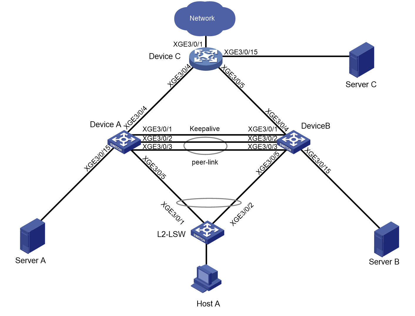
Table 1 Interfaces and IP address assignment
|
Device |
Interface |
IP address |
Remarks or peer interfaces |
|
Device A |
LoopBack 0 |
3.3.3.3/32 2000::3:3:3:3/128 |
Loopback interface address Router ID |
|
XGE 3/0/5 |
N/A |
L2-LSW: XGE3/0/1 M-LAG interface |
|
|
XGE 3/0/15 |
N/A |
Server A |
|
|
XGE 3/0/4 |
32.1.1.1/24 32::1/64 |
Device C: XGE 3/0/4 |
|
|
XGE 3/0/1 |
21.1.1.1/24 |
Device B XGE 3/0/1 Keepalive link |
|
|
XGE 3/0/2 |
N/A |
Device B XGE 3/0/2 Peer-link interface |
|
|
XGE 3/0/3 |
N/A |
Device B XGE 3/0/3 Peer-link interface |
|
|
VLAN 100 |
100.1.1.1/24 100::1/64 |
Dual-active gateways |
|
|
VLAN 101 |
101.1.1.1/24 101::1/64 |
Layer 3 link connecting the two M-LAG member devices, which is used for forwarding east-west traffic or used as the failover link for north-south traffic or Layer 3 remote mirrored traffic. |
|
|
Device B |
LoopBack 0 |
4.4.4.4/32 2000::4:4:4:4/128 |
Loopback interface address Router ID. |
|
XGE 3/0/5 |
N/A |
L2-LSW: XGE3/0/2 M-LAG interface |
|
|
XGE 3/0/4 |
33.1.1.1/24 33::1/64 |
Device C: XGE 3/0/5 |
|
|
XGE 3/0/15 |
N/A |
Server B |
|
|
XGE 3/0/1 |
21.1.1.2/24 |
Device A: XGE 3/0/1 Keepalive link |
|
|
XGE 3/0/2 |
N/A |
Device A: XGE 3/0/2 Peer-link interface |
|
|
XGE 3/0/3 |
N/A |
Device A: XGE 3/0/3 Peer-link interface |
|
|
VLAN 100 |
100.1.1.1/24 100::1/64 |
Dual-active gateways |
|
|
VLAN 101 |
101.1.1.2/24 101::2/64 |
Interface of the Layer 3 link connecting the two M-LAG member devices, which is used for forwarding east-west traffic or allowing north-south traffic or Layer 3 remote mirrored traffic to escape. |
|
|
Device C |
LoopBack 0 |
5.5.5.5/32 2000::5:5:5:5/128 |
Loopback interface address Router ID. |
|
XGE 3/0/1 |
22.1.1.1/24 22::1/64 |
Network 1 |
|
|
XGE 3/0/4 |
32.1.1.2/24 32::2/64 |
Device A: XGE 3/0/4 |
|
|
XGE 3/0/5 |
33.1.1.2/24 33::2/64 |
Device B XGE 3/0/4 |
|
|
XGE 3/0/15 |
2.1.1.1/24 |
Server C |
|
|
L2-LSW |
XGE 3/0/1 |
N/A |
Device A: XGE 3/0/5 M-LAG interface |
|
XGE 3/0/2 |
N/A |
Device B XGE 3/0/5 M-LAG interface |
|
|
XGE 3/0/3 |
N/A |
Host A |
|
|
Host A |
N/A |
100.1.1.100/24 100::100/64 |
L2-LSW: XGE 3/0/3 |
|
Network 1 |
N/A |
22.1.1.100/24 22::100/64 |
Device C: XGE 3/0/1 |
|
Server C |
N/A |
2.1.1.2/24 |
Device C: XGE 3/0/15 |
Applicable product matrixes
|
|
NOTE: In addition to running an applicable software version, you must also install the most recent patch, if any. |
Table 2 Applicable product matrix 1
|
Device |
Software version |
|
S10500, S10500X, S7600, S7600-X, S7600E-X, S7500X, S7500E |
R7625 and later |
|
S12500G-AF (type T cards) |
R7625 and later |
Table 3 Applicable product matrix 2
|
Device |
Software version |
|
S12500G-AF (type S cards) |
R8054P04 and later |
|
S10500X-G, S7500X-G |
R7754P04 and later |
|
S5590XP-HI-G |
R7754P04 and later |
Analysis
· Device A and Device B act as dual-active gateways for Host A through M-LAG.
· Host A connects to the network through two uplinks. Configure the IP address of VLAN 100 as the gateway address.
· Server A, Server B, and Server C act as mirroring servers.
· Device A and Device B are connected to uplink device Device C through equal-cost routes.
· Configure an OSPF/OSPFv3 neighbor between Device A and Device B, which is used as the failover link for Layer 3 remote mirrored traffic and normal traffic.
· The network is configured with both IPv4 and IPv6 settings.
Restrictions and guidelines
All the devices were started with the factory default configuration. When you are working on a live network, make sure the existing configuration does not conflict with the following configuration.
VLAN flow mirroring and global flow mirroring support only inbound mirroring.
A peer-link interface cannot act as the monitor port.
Configure M-LAG devices
Procedure summary
· Configuring the interconnect links between the M-LAG member devices and Layer 2 switch
· Configuring the Layer 3 link connecting the M-LAG member devices
· Configuring the M-LAG dual-active gateways
· Configuring the interconnect links between the M-LAG system and the uplink device Device C
Configuring M-LAG
|
Device A |
Device B |
Description |
Remarks |
|
m-lag system-mac 2-2-2 |
m-lag system-mac 2-2-2 |
Configure the M-LAG system MAC address. |
You must assign the same system MAC address to all member devices in an M-LAG system. |
|
m-lag system-mac 1 |
m-lag system-mac 2 |
Set the M-LAG system number. |
You must assign different M-LAG system numbers to the member devices in an M-LAG system. |
|
m-lag system-mac 123 |
m-lag system-mac 123 |
Set the M-LAG system priority. |
You must set the same LAG system priority on all member devices in an M-LAG system. |
|
m-lag standalone enable |
m-lag standalone enable |
(Optional.) Enable M-LAG standalone mode. |
M-LAG standalone mode helps avoid traffic forwarding issues in this multi-active situation by allowing only the member ports in the M-LAG interfaces on one member device to forward traffic. |
|
m-lag restore-delay 300 |
m-lag restore-delay 300 |
Set the maximum amount of time for the secondary M-LAG member device to synchronize data with the primary M-LAG member device during M-LAG system setup, such as MAC address entries. |
N/A |
|
m-lag keepalive ip destination 21.1.1.2 source 21.1.1.1 |
m-lag keepalive ip destination 21.1.1.1 source 21.1.1.2 |
Configure the source and destination IPv4 addresses of keepalive packets. |
N/A |
|
interface Ten-gigabitethernetE3/0/1 |
interface Ten-gigabitethernetE3/0/1 |
Enter the interface view for the keepalive link. |
N/A |
|
port link-mode route |
port link-mode route |
Configure the interface for the keepalive link to operate in route mode as a Layer 3 interface. |
N/A |
|
ip address 21.1.1.1 24 |
ip address 21.1.1.2 24 |
Configure the source IPv4 address of keepalive packets. |
N/A |
|
quit |
quit |
Return to system view. |
N/A |
|
m-lag mad exclude interface Ten-gigabitethernetE3/0/1 |
m-lag mad exclude interface Ten-gigabitethernetE3/0/1 |
Exclude the interface for the keepalive link from the shutdown action by M-LAG MAD. |
N/A |
|
interface bridge-aggregation 1 |
interface bridge-aggregation 1 |
Create an aggregate interface. |
The interface is used as the peer-ink interface. |
|
link-aggregation mode dynamic |
link-aggregation mode dynamic |
Configure the aggregate interface to operate in dynamic mode. |
N/A |
|
quit |
quit |
Return to system view. |
N/A |
|
interface range Ten-gigabitethernetE 3/0/2 Ten-gigabitethernetE 3/0/3 |
interface range Ten-gigabitethernetE 3/0/2 Ten-gigabitethernetE 3/0/3 |
Enter interface range view. |
N/A |
|
port link-aggregation group 1 |
port link-aggregation group 1 |
Assign the physical interfaces on the peer link to the M-LAG aggregation group. |
N/A |
|
quit |
quit |
Return to system view. |
N/A |
|
interface bridge-aggregation 1 |
interface bridge-aggregation 1 |
Enter aggregate interface view. |
N/A |
|
port m-lag peer-link 1 |
port m-lag peer-link 1 |
Specify the aggregate interface as the peer-link interface. |
N/A |
|
undo mac-address static source-check enable |
undo mac-address static source-check enable |
Disable source MAC check to ensure correct Layer 3 unicast forwarding. |
N/A |
|
quit |
quit |
Return to system view. |
N/A |
|
lldp global enable |
lldp global enable |
Enable LLDP globally. |
N/A |
Configuring the interconnect links between the M-LAG member devices and Layer 2 switch
|
Device A |
Device B |
Description |
|
interface bridge-aggregation 2 |
interface bridge-aggregation 2 |
Create the Ethernet aggregate interface connecting to L2-LSW. |
|
link-aggregation mode dynamic |
link-aggregation mode dynamic |
Configure the aggregate interface connecting to L2-LSW to operate in dynamic mode. |
|
port m-lag group 1 |
port m-lag group 1 |
Assign the aggregate interface (Bridge-Aggregation 2) to M-LAG group 1. |
|
port lacp system-priority 100 |
port lacp system-priority 101 |
Set the LACP system priority, so that only member ports with higher priority are selected upon brain split. |
|
quit |
quit |
Return to system view. |
|
interface Ten-gigabitethernetE 3/0/5 |
interface Ten-gigabitethernetE 3/0/5 |
Enter the view of the physical interface connecting the M-LAG system to L2-LSW. |
|
port link-aggregation group 2 |
port link-aggregation group 2 |
Assign the interface to an aggregation group. |
|
quit |
quit |
Return to system view. |
Configuring the Layer 3 link connecting the M-LAG member devices
|
Device A |
Device B |
Description |
Remarks |
|
router id 3.3.3.3 |
router id 4.4.4.4 |
Configure a router ID. |
N/A |
|
ospf 1 |
ospf 1 |
Enable OSPF. |
N/A |
|
import-route direct |
import-route direct |
Redistribute direct routes. |
N/A |
|
area 0 |
area 0 |
Configure area 0. |
N/A |
|
quit |
quit |
Return to OSPF view. |
N/A |
|
quit |
quit |
Return to system view. |
N/A |
|
ospfv3 1 |
ospfv3 1 |
Enable OSPFv3 |
N/A |
|
router-id 3.3.3.3 |
router-id 4.4.4.4 |
Configure a router ID. |
N/A |
|
import-route direct |
import-route direct |
Redistribute direct routes. |
N/A |
|
area 0 |
area 0 |
Configure area 0. |
N/A |
|
quit |
quit |
Return to OSPFv3 view. |
N/A |
|
quit |
quit |
Return to system view. |
N/A |
|
interface Loopback 0 |
interface Loopback 0 |
Configure a loopback interface. |
N/A |
|
ip address 3.3.3.3 255,255,255,255 |
ip address 4.4.4.4 255,255,255,255 |
Configure an IPv4 address for the loopback interface. |
N/A |
|
ospf 1 area 0 |
ospf 1 area 0 |
Enable OSPF on the loopback interface. |
N/A |
|
ipv6 address 2000::3:3:3:3/128 |
ipv6 address 2000::4:4:4:4/128 |
Configure an IPv6 address for the loopback interface. |
N/A |
|
ospfv3 1 area 0 |
ospfv3 1 area 0 |
Enable OSPFv3 on the loopback interface. |
N/A |
|
quit |
quit |
Return to system view. |
N/A |
|
vlan 101 |
vlan 101 |
Create VLAN 101. |
N/A |
|
quit |
quit |
Return to system view. |
N/A |
|
interface vlan-interface 101 |
interface vlan-interface 101 |
Create VLAN-interface 101. |
Layer 3 link connecting the two M-LAG member devices, which is used for forwarding east-west traffic or used as the failover link for north-south traffic or Layer 3 remote mirrored traffic. |
|
ip address 101.1.1.1 255.255.255.0 |
ip address 101.1.1.2 255.255.255.0 |
Assign an IPv4 address to VLAN interface 101. |
N/A |
|
ospf 1 area 0 |
ospf 1 area 0 |
Enable OSPF on the VLAN interface |
N/A |
|
ospf network-type p2p |
ospf network-type p2p |
Configure the OSPF network type for the interface as P2P. |
|
|
ipv6 address 101::1 64 |
ipv6 address 101::2 64 |
Assign an IPv6 address to VLAN interface 101. |
N/A |
|
ospfv3 1 area 0 |
ospfv3 1 area 0 |
Enable OSPFv3 on the VLAN interface. |
N/A |
|
ospfv3 network-type p2p |
ospfv3 network-type p2p |
Configure the OSPF network type for the VLAN interface as P2P. |
|
|
quit |
quit |
Return to system view. |
N/A |
|
m-lag mad exclude interface Vlan-interface 101 |
m-lag mad exclude interface Vlan-interface 101 |
Exclude the VLAN interface from the shutdown action by M-LAG MAD. |
N/A |
Configuring the M-LAG dual-active gateways
|
Device A |
Device B |
Description |
Remarks |
|
vlan 100 |
vlan 100 |
Create VLAN 100. |
N/A |
|
quit |
quit |
Return to system view. |
N/A |
|
interface bridge-aggregation 2 |
interface bridge-aggregation 2 |
Enter Ethernet aggregate interface view. |
N/A |
|
port link-type trunk |
port link-type trunk |
Set the link type of the Layer 2 aggregate interface (Bridge-Aggregation 2) to trunk. |
N/A |
|
port trunk permit vlan 1 100 |
port trunk permit vlan 1 100 |
Assign the aggregate interface to VLAN 100. |
N/A |
|
undo port trunk permit vlan 1 |
undo port trunk permit vlan 1 |
Remove the aggregate interface from VLAN 1. |
N/A |
|
quit |
quit |
Return to system view. |
N/A |
|
interface vlan-interface 100 |
interface vlan-interface 100 |
Create VLAN interface 100. |
N/A |
|
ip address 100.1.1.1 24 |
ip address 100.1.1.1 24 |
Assign an IPv4 address to VLAN interface 100. |
The address acts as the IPv4 dual-active gateway. |
|
ipv6 address 100::1 64 |
ipv6 address 100::1 64 |
Assign an IPv6 address to VLAN interface 100. |
The address acts as the IPv6 dual-active gateway. |
|
mac-address 0002-2222-2222 |
mac-address 0002-2222-2222 |
Assign a MAC address to VLAN interface 100. |
N/A |
|
quit |
quit |
Return to system view. |
N/A |
|
m-lag mad exclude interface Vlan-interface100 |
m-lag mad exclude interface Vlan-interface100 |
Exclude VLAN interface 100 from the shutdown action by M-LAG MAD. |
For M-LAG member devices to synchronize ARP/ND entries, you must exclude the VLAN interfaces of the VLANs to which the M-LAG interfaces belong from the shutdown action. |
Configuring the interconnect links between the M-LAG system and the uplink device Device C
|
Device A |
Device B |
Description |
|
interface Ten-gigabitethernetE 3/0/4 |
interface Ten-gigabitethernetE 3/0/4 |
Enter Ethernet interface view. |
|
port link-mode route |
port link-mode route |
Configure the interface as a Layer 3 interface. |
|
ip address 32.1.1.1 24 |
ip address 33.1.1.1 24 |
Configure an IPv4 address. |
|
ospf 1 area 0 |
ospf 1 area 0 |
Enable OSPF on the interface. |
|
ospf network-type p2p |
ospf network-type p2p |
Configure the OSPF network type for the interface as P2P. |
|
ipv6 address 32::1 64 |
ipv6 address 33::1 64 |
Configure an IPv6 address. |
|
ospfv3 1 area 0 |
ospfv3 1 area 0 |
Enable OSPFv3 on the interface. |
|
ospfv3 network-type p2p |
ospfv3 network-type p2p |
Configure the OSPFv3 network type for the interface as P2P. |
|
quit |
quit |
Return to system view. |
Configuring uplink device Device C
Procedure summary
· Configuring the interconnect links between the uplink device Device C and the M-LAG member devices
· Configuring the interconnect link between the uplink device Device C and the network
· Configuring the interconnect link between the uplink device Device C and the mirroring server
Configuring the interconnect links between the uplink device Device C and the M-LAG member devices
|
Device C |
Description |
|
router id 5.5.5.5 |
Configure a router ID. |
|
ospf 1 |
Enable OSPF. |
|
import-route direct |
Redistribute direct routes. |
|
area 0 |
Configure area 0. |
|
quit |
Return to OSPF view. |
|
quit |
Return to system view. |
|
ospfv3 1 |
Enable OSPFv3. |
|
router-id 5.5.5.5 |
Configure a router ID. |
|
import-route direct |
Redistribute direct routes. |
|
area 0 |
Configure area 0. |
|
quit |
Return to OSPFv3 view. |
|
quit |
Return to system view. |
|
interface Loopback 0 |
Configure a loopback interface. |
|
ip address 5.5.5.5 255,255,255,255 |
Configure an IPv4 address for the interface. |
|
ospf 1 area 0.0.0.0 |
Enable OSPF on the loopback interface. |
|
ipv6 address 2000::5:5:5:5/128 |
Configure an IPv6 address for the interface. |
|
ospfv3 1 area 0.0.0.0 |
Enable OSPFv3 on the interface. |
|
quit |
Return to system view. |
|
interface Ten-gigabitethernetE 3/0/4 |
Enter Ethernet interface view. |
|
port link-mode route |
Configure the interface as a Layer 3 interface. |
|
ip address 32.1.1.1 24 |
Configure an IPv4 address. |
|
ospf 1 area 0 |
Enable OSPF on the interface. |
|
ospf network-type p2p |
Configure the OSPF network type for the interface as P2P. |
|
ipv6 address 32::1 64 |
Configure an IPv6 address. |
|
ospfv3 1 area 0 |
Enable OSPFv3 on the interface. |
|
ospfv3 network-type p2p |
Configure the OSPFv3 network type for the interface as P2P. |
|
quit |
Return to system view. |
|
interface Ten-gigabitethernetE 3/0/5 |
Enter Ethernet interface view. |
|
port link-mode route |
Configure the interface as a Layer 3 interface. |
|
ip address 33.1.1.1 24 |
Configure IPv4 an address. |
|
ospf 1 area 0 |
Enable OSPF on the interface. |
|
ipv6 address 33::1 64 |
Configure an IPv6 address. |
|
ospfv3 1 area 0 |
Enable OSPFv3 on the interface. |
|
quit |
Return to system view. |
|
lldp global enable |
Enable LLDP globally. |
Configuring the interconnect link between the uplink device Device C and the network
|
Device C |
Description |
|
interface Ten-gigabitethernetE 3/0/1 |
Enter Ethernet interface view. |
|
port link-mode route |
Configuring the interface as a Layer 3 interface. |
|
ip address 22.1.1.1 255.255.255.0 |
Assign an IPv4 address to the interface. |
|
ipv6 address 22::1/64 |
Assign an IPv6 address to the interface. |
|
quit |
Return to system view. |
Configuring the interconnect link between the uplink device Device C and the mirroring server
|
Device C |
Description |
|
vlan 2 |
Create a VLAN. |
|
quit |
Return to system view. |
|
interface Ten-gigabitethernetE 3/0/15 |
Enter Ethernet interface view. |
|
port access vlan 2 |
Assign the interface to VLAN 2 as an access port. |
|
quit |
Return to system view. |
|
interface Vlan-interface2 |
Create VLAN interface 2, which is used to connect with the mirroring server. |
|
ip address 2.1.1.1 255.255.255.0 |
Configure an IPv4 address. |
|
quit |
Return to system view. |
Configuring downlink device L2-LSW
Procedure summary
· Configuring the interconnect links between the downlink device L2-LSW and the M-LAG member devices
· Configuring the interconnect link between the downlink device Device D and the host
Configuring the interconnect links between the downlink device L2-LSW and the M-LAG member devices
|
L2-LSW |
Description |
|
vlan 100 |
Create a VLAN. |
|
quit |
Return to system view. |
|
interface bridge-aggregation 2 |
Create the Ethernet aggregate interface connecting to M-LAG member devices. |
|
link-aggregation mode dynamic |
Configure the aggregate interface to operate in dynamic mode. |
|
quit |
Return to system view. |
|
interface Range Ten-gigabitethernetE 3/0/1 to Ten-gigabitethernetE 3/0/2 |
Enter the view of the physical interfaces connecting the L2-LSW to M-LAG member devices. |
|
port link-aggregation group 2 |
Assign the interfaces to an aggregation group. |
|
quit |
Return to system view. |
|
interface bridge-aggregation 2 |
Enter Ethernet aggregate interface view. |
|
port access vlan 100 |
Assign the interfaces to VLAN 100. |
|
quit |
Return to system view. |
|
lldp global enable |
Enable LLDP globally. |
Configuring the interconnect link between the downlink device Device D and the host
|
L2-LSW |
Description |
Remarks |
|
interface Ten-gigabitethernetE 3/0/3 |
Enter Ethernet interface view. |
N/A |
|
port access vlan 100 |
Assign the interface (which connects L2-LSW to the host) to VLAN 100 as an access port. |
N/A |
|
quit |
Return to system view. |
N/A |
Configure traffic mirroring
Procedure summary
· Configure local port mirroring
· Configure local flow mirroring to mirroring traffic to an interface
· Configure local flow mirroring to mirror traffic on all interfaces in a VLAN
· Configure global flow mirroring to mirror traffic on all interfaces on the device
· Configure port mirroring ERSPAN (applicable product matrix 1)
· Configure port mirroring ERSPAN (applicable product matrix 2)
· Configure flow mirroring ERSPAN
Configure local port mirroring
|
Device A |
Device B |
Description |
|
mirroring-group 1 local |
mirroring-group 1 local |
Configuring a local port mirroring group. |
|
mirroring-group 1 mirroring-port Ten-GigabitEthernet 3/0/5 both |
mirroring-group 1 mirroring-port Ten-GigabitEthernet 3/0/5 both |
Configure the source ports for local mirroring. |
|
mirroring-group 1 mirror-port Ten-GigabitEthernet 3/0/15 |
mirroring-group 1 mirror-port Ten-GigabitEthernet 3/0/15 |
Configure the mirroring destination port. |
Configure local flow mirroring to mirroring traffic to an interface
|
Device A |
Device B |
Description |
|
acl number 3000 |
acl number 3000 |
Create ACL 3000. |
|
rule permit tcp source 100.1.1.100 0.0.0.0 |
rule permit tcp source 100.1.1.100 0.0.0.0 |
Configure an ACL rule for inbound traffic. |
|
quit |
quit |
Return to system view. |
|
acl number 3001 |
acl number 3001 |
Create ACL 3001. |
|
rule permit tcp destination 100.1.1.100 0.0.0.0 |
rule permit tcp destination 100.1.1.100 0.0.0.0 |
Configure an ACL rule for outbound traffic. |
|
quit |
quit |
N/A |
|
acl ipv6 number 3000 |
acl ipv6 number 3000 |
Create IPv6 ACL 3001. |
|
rule permit tcp source 100::100 128 |
rule permit tcp source 100::100 128 |
Configure an IPv6 ACL rule for inbound traffic. |
|
quit |
quit |
Return to system view. |
|
acl ipv6 number 3001 |
acl ipv6 number 3001 |
Create IPv6 ACL 3001. |
|
rule permit tcp destination 100::100 128 |
rule permit tcp destination 100::100 128 |
Configure an IPv6 ACL rule for outbound traffic. |
|
quit |
quit |
Return to system view |
|
traffic classifier test-ipv4-in |
traffic classifier test-ipv4-in |
Create a traffic class for inbound IPv4 traffic. |
|
if-match acl 3000 |
if-match acl 3000 |
Use ACL 3000 as the match criterion. |
|
quit |
quit |
Return to system view |
|
traffic classifier test-ipv4-out |
traffic classifier test-ipv4-out |
Create a traffic class for outbound IPv4 traffic. |
|
if-match acl 3001 |
if-match acl 3001 |
Use ACL 3001 as the match criterion. |
|
quit |
quit |
Return to system view |
|
traffic classifier test-ipv6-in |
traffic classifier test-ipv6-in |
Create a traffic class for inbound IPv6 traffic. |
|
if-match acl ipv6 3000 |
if-match acl ipv6 3000 |
Use ACL 3000 as the match criterion. |
|
quit |
quit |
Return to system view |
|
traffic classifier test-ipv6-out |
traffic classifier test-ipv6-out |
Create a traffic class for outbound IPv6 traffic. |
|
if-match acl ipv6 3001 |
if-match acl ipv6 3001 |
Use ACL 3001 as the match criterion. |
|
quit |
quit |
Return to system view. |
|
traffic behavior mir |
traffic behavior mir |
Configure traffic mirroring behavior |
|
mirror-to interface Ten-gigabitethernet 3/0/15 |
mirror-to interface Ten-gigabitethernet 3/0/15 |
Configure an action of mirroring traffic to the mirroring server. |
|
quit |
quit |
Return to system view. |
|
qos policy test-in |
qos policy test-in |
Create a QoS policy for inbound traffic. |
|
classifier test-ipv4-in behavior mir |
classifier test-ipv4-in behavior mir |
Associate the traffic class with the traffic behavior for IPv4 traffic. |
|
classifier test-ipv6-in behavior mir |
classifier test-ipv6-in behavior mir |
Associate the traffic class with the traffic behavior for IPv6 traffic. |
|
quit |
quit |
Return to system view |
|
qos policy test-out |
qos policy test-out |
Create a QoS policy for outbound traffic. |
|
classifier test-ipv4-out behavior mir |
classifier test-ipv4-out behavior mir |
Associate the traffic class with the traffic behavior for IPv4 traffic. |
|
classifier test-ipv6-out behavior mir |
classifier test-ipv6-out behavior mir |
Associate the traffic class with the traffic behavior for IPv6 traffic. |
|
quit |
quit |
Return to system view |
|
interface Ten-gigabitethernet 3/0/5 |
interface Ten-gigabitethernet 3/0/5 |
Enter the view of the source port. |
|
qos apply policy test-in inbound |
qos apply policy test-in inbound |
Apply the QoS policy to the inbound direction of the interface. |
|
qos apply policy test-out outbound |
qos apply policy test-out outbound |
Apply the QoS policy to the outbound direction of the interface. |
|
quit |
quit |
Return to system view |
Configure local flow mirroring to mirror traffic on all interfaces in a VLAN
|
Device A |
Device B |
Description |
|
acl number 3000 |
acl number 3000 |
Create ACL 3000. |
|
rule permit tcp source 100.1.1.100 0.0.0.0 |
rule permit tcp source 100.1.1.100 0.0.0.0 |
Configure an ACL rule for inbound traffic. |
|
quit |
quit |
Return to system view |
|
acl ipv6 number 3000 |
acl ipv6 number 3000 |
Create IPv6 ACL 3001. |
|
rule permit tcp source 100::100 128 |
rule permit tcp source 100::100 128 |
Configure an IPv6 ACL rule for inbound traffic. |
|
quit |
quit |
Return to system view |
|
traffic classifier test-ipv4-in |
traffic classifier test-ipv4-in |
Create a QoS traffic class for inbound IPv4 traffic. |
|
if-match acl 3000 |
if-match acl 3000 |
Use ACL 3000 as the match criterion. |
|
quit |
quit |
Return to system view |
|
traffic classifier test-ipv6-in |
traffic classifier test-ipv6-in |
Create a traffic class for inbound IPv6 traffic. |
|
if-match acl ipv6 3000 |
if-match acl ipv6 3000 |
Use ACL 3000 as the match criterion. |
|
quit |
quit |
Return to system view |
|
traffic behavior mir |
traffic behavior mir |
Create a traffic behavior. |
|
mirror-to interface Ten-gigabitethernet 3/0/15 |
mirror-to interface Ten-gigabitethernet 3/0/15 |
Configure an action of mirroring traffic to the mirroring server. |
|
quit |
quit |
Return to system view |
|
qos policy test-in |
qos policy test-in |
Create a QoS policy. |
|
classifier test-ipv4-in behavior mir |
classifier test-ipv4-in behavior mir |
Associate the traffic class with the traffic behavior for IPv4 traffic. |
|
classifier test-ipv6-in behavior mir |
classifier test-ipv6-in behavior mir |
Associate the traffic class with the traffic behavior for IPv6 traffic. |
|
quit |
quit |
Return to system view |
|
qos vlan-policy test-in vlan 100 inbound |
qos vlan-policy test-in vlan 100 inbound |
Apply the QoS policy to the inbound direction of the VLAN. |
Configure global flow mirroring to mirror traffic on all interfaces on the device
|
Device A |
Device B |
Description |
|
acl number 3000 |
acl number 3000 |
Create ACL 3000. |
|
rule permit tcp source 100.1.1.100 0.0.0.0 |
rule permit tcp source 100.1.1.100 0.0.0.0 |
Configure an ACL rule for inbound traffic. |
|
quit |
quit |
Return to system view |
|
acl ipv6 number 3000 |
acl ipv6 number 3000 |
Create IPv6 ACL 3001. |
|
rule permit tcp source 100::100 128 |
rule permit tcp source 100::100 128 |
Configure an IPv6 ACL rule for inbound traffic. |
|
quit |
quit |
Return to system view |
|
traffic classifier test-ipv4-in |
traffic classifier test-ipv4-in |
Create a QoS traffic class for inbound IPv4 traffic. |
|
if-match acl 3000 |
if-match acl 3000 |
Use ACL 3000 as the match criterion. |
|
quit |
quit |
Return to system view |
|
traffic classifier test-ipv6-in |
traffic classifier test-ipv6-in |
Create a traffic class for inbound IPv6 traffic. |
|
if-match acl ipv6 3000 |
if-match acl ipv6 3000 |
Use ACL 3000 as the match criterion. |
|
quit |
quit |
Return to system view |
|
traffic behavior mir |
traffic behavior mir |
Configure a traffic behavior. |
|
mirror-to interface Ten-gigabitethernet 3/0/15 |
mirror-to interface Ten-gigabitethernet 3/0/15 |
Configure an action of mirroring traffic to the mirroring server. |
|
qos policy test-in |
qos policy test-in |
Create a QoS policy. |
|
classifier test-ipv4-in behavior mir |
classifier test-ipv4-in behavior mir |
Associate the traffic class with the traffic behavior for IPv4 traffic. |
|
classifier test-ipv6-in behavior mir |
classifier test-ipv6-in behavior mir |
Associate the traffic class with the traffic behavior for IPv6 traffic. |
|
quit |
quit |
Return to system view |
|
qos apply policy test-in global inbound |
qos apply policy test-in global inbound |
Apply the QoS policy to the inbound direction globally. |
Configure port mirroring ERSPAN (applicable product matrix 1)
|
Device A |
Device B |
Description |
|
service-loopback group 1 type tunnel |
service-loopback group 1 type tunnel |
Create service loopback group 1, and specify the tunnel service for the group. |
|
interface Ten-gigabitethernet 3/0/8 |
interface Ten-gigabitethernet 3/0/8 |
Enter interface view. The interface can be any interface that has not been used. |
|
port service-loopback group 1 |
port service-loopback group 1 |
Assign Ten-GigabitEthernet 3/0/8 to service loopback group 1. |
|
quit |
quit |
Return to system view |
|
interface tunnel 1 mode gre |
interface tunnel 1 mode gre |
Create tunnel interface Tunnel 1 that operates in GRE mode. |
|
ip address 50.1.1.1 24 |
ip address 50.2.1.1 24 |
Configure an IP address. |
|
source LoopBack0 |
source LoopBack0 |
Configure a source IP address for Tunnel 1. |
|
destination 5.5.5.5 |
destination 5.5.5.5 |
Configure a destination IP address for Tunnel 1. |
|
quit |
quit |
Return to system view |
|
mirroring-group 1 local |
mirroring-group 1 local |
Create a local mirroring group. |
|
mirroring-group 1 mirroring-port Ten-GigabitEthernet 3/0/5 both |
mirroring-group 1 mirroring-port Ten-GigabitEthernet 3/0/5 both |
Configure Ten-GigabitEthernet 3/0/5 as a source port of local mirroring group 1. |
|
mirroring-group 1 monitor-port tunnel 1 |
mirroring-group 1 monitor-port tunnel 1 |
Configure Tunnel 1 as the monitor port of local mirroring group 1. |
|
Device C |
Description |
|
service-loopback group 1 type tunnel |
Create service loopback group 1, and specify the tunnel service for the group. |
|
interface Ten-gigabitethernet 3/0/8 |
Enter the view of Ten-GigabitEthernet 3/0/8. The interface can be any interface that has not been used. |
|
port service-loopback group 1 |
Assign Ten-GigabitEthernet 3/0/8 to service loopback group 1. |
|
quit |
Return to system view |
|
interface tunnel 1 mode gre |
Create GRE tunnel interface 1. |
|
ip address 50.1.1.2 24 |
Configure an IP address. |
|
source LoopBack0 |
Configure a source IP address for Tunnel 1. |
|
destination 3.3.3.3 |
Configure a destination IP address for Tunnel 1. |
|
quit |
Return to system view |
|
interface tunnel 2 mode gre |
Create tunnel interface Tunnel 2 that operates in GRE mode. |
|
ip address 50.2.1.2 24 |
Configure an IP address. |
|
source LoopBack0 |
Configure a source IP address for Tunnel 2. |
|
destination 4.4.4.4 |
Configure a destination IP address for Tunnel 2. |
|
quit |
Return to system view |
|
mirroring-group 1 local |
Create a local mirroring group. |
|
mirroring-group 1 mirroring-port Ten-GigabitEthernet 3/0/4 Ten-GigabitEthernet 3/0/5 inbound |
Configure Ten-GigabitEthernet 3/0/4 and Ten-GigabitEthernet 3/0/5 as source ports of local mirroring group 1. |
|
mirroring-group 1 monitor-port Ten-GigabitEthernet 3/0/15 |
Configure Ten-GigabitEthernet 3/0/15 as the monitor port of local mirroring group 1. |
|
acl number 3000 |
To prevent GRE mirrored packets from being used for other purposes, use ACLs to filter them. |
|
rule deny gre source 3.3.3.3 0 destination 5.5.5.5 0 |
Configure a rule to match GRE mirrored packets. |
|
rule deny gre source 4.4.4.4 0 destination 5.5.5.5 0 |
Configure a rule to match GRE mirrored packets. |
|
quit |
Return to system view. |
|
interface range Ten-gigabitethernet 3/0/4 to Ten-gigabitethernet 3/0/5 |
Enter the view of the source ports. |
|
packet-filter 3000 inbound |
Apply ACL 3000 to the inbound direction of the interfaces. |
|
quit |
Return to system view |
Configure port mirroring ERSPAN (applicable product matrix 2)
|
Device A |
Device B |
Description |
|
mirroring-group 1 local |
mirroring-group 1 local |
Configure a local mirroring group. |
|
mirroring-group 1 mirroring-port Ten-GigabitEthernet 3/0/5 both |
mirroring-group 1 mirroring-port Ten-GigabitEthernet 3/0/5 both |
Configure a source port for the mirroring group. |
|
mirroring-group 1 monitor-port Ten-GigabitEthernet 3/0/4 destination-ip 2.1.1.2 source-ip 32.1.1.1 |
mirroring-group 1 monitor-port Ten-GigabitEthernet 3/0/4 destination-ip 2.1.1.2 source-ip 33.1.1.1 |
Configure the monitor port for the mirroring group. |
Configure flow mirroring ERSPAN
|
Device A |
Device B |
Description |
|
acl number 3000 |
acl number 3000 |
Create ACL 3000. |
|
rule permit tcp source 100.1.1.100 0.0.0.0 |
rule permit tcp source 100.1.1.100 0.0.0.0 |
Configure an ACL rule for inbound traffic. |
|
quit |
quit |
Return to system view |
|
acl number 3001 |
acl number 3001 |
Create ACL 3001. |
|
rule permit tcp destination 100.1.1.100 0.0.0.0 |
rule permit tcp destination 100.1.1.100 0.0.0.0 |
Configure an ACL rule for outbound traffic. |
|
quit |
quit |
Return to system view |
|
acl ipv6 number 3000 |
acl ipv6 number 3000 |
Create IPv6 ACL 3001. |
|
rule permit tcp source 100::100 128 |
rule permit tcp source 100::100 128 |
Configure an IPv6 ACL rule for inbound traffic. |
|
quit |
quit |
Return to system view |
|
acl ipv6 number 3001 |
acl ipv6 number 3001 |
Create IPv6 ACL 3001. |
|
rule permit tcp destination 100::100 128 |
rule permit tcp destination 100::100 128 |
Configure an IPv6 ACL rule for outbound traffic. |
|
quit |
quit |
Return to system view |
|
traffic classifier test-ipv4-in |
traffic classifier test-ipv4-in |
Create a QoS traffic class for inbound traffic. |
|
if-match acl 3000 |
if-match acl 3000 |
Use ACL 3000 as the match criterion. |
|
quit |
quit |
Return to system view |
|
traffic classifier test-ipv4-out |
traffic classifier test-ipv4-out |
Configure a traffic class for outbound IPv4 traffic. |
|
if-match acl 3001 |
if-match acl 3001 |
Use ACL 3001 as the match criterion. |
|
quit |
quit |
Return to system view |
|
traffic classifier test-ipv6-in |
traffic classifier test-ipv6-in |
Create a traffic class for inbound IPv6 traffic. |
|
if-match acl ipv6 3000 |
if-match acl ipv6 3000 |
Use ACL 3000 as the match criterion. |
|
quit |
quit |
Return to system view |
|
traffic classifier test-ipv6-out |
traffic classifier test-ipv6-out |
Create a traffic class for outbound IPv6 traffic. |
|
if-match acl ipv6 3001 |
if-match acl ipv6 3001 |
Use ACL 3001 as the match criterion. |
|
quit |
quit |
Return to system view |
|
traffic behavior mir |
traffic behavior mir |
Create a traffic behavior. |
|
mirror-to interface destination-ip 2.1.1.2 source-ip 3.3.3.3 |
mirror-to interface destination-ip 2.1.1.2 source-ip 4.4.4.4 |
Mirror traffic to mirroring servers. |
|
quit |
quit |
Return to system view |
|
qos policy test-in |
qos policy test-in |
Create a QoS policy. |
|
classifier test-ipv4-in behavior mir |
classifier test-ipv4-in behavior mir |
Associate the traffic class with the traffic behavior for IPv4 traffic. |
|
classifier test-ipv6-in behavior mir |
classifier test-ipv6-in behavior mir |
Associate the traffic class with the traffic behavior for IPv6 traffic. |
|
quit |
quit |
Return to system view |
|
qos policy test-out |
qos policy test-out |
Create a QoS policy for outbound traffic. |
|
classifier test-ipv4-out behavior mir |
classifier test-ipv4-out behavior mir |
Associate the traffic class with the traffic behavior for IPv4 traffic. |
|
classifier test-ipv6-out behavior mir |
classifier test-ipv6-out behavior mir |
Associate the traffic class with the traffic behavior for IPv6 traffic. |
|
Quit |
quit |
Return to system view |
|
interface Ten-gigabitethernet 3/0/5 |
interface Ten-gigabitethernet 3/0/5 |
Enter the view of the source port. |
|
qos apply policy test-in inbound |
qos apply policy test-in inbound |
Apply the QoS policy to the inbound direction of the interface. |
|
qos apply policy test-out outbound |
qos apply policy test-out outbound |
Apply the QoS policy to the outbound direction of the interface. |
|
quit |
quit |
Return to system view |
Traffic forwarding models
About the traffic model
The traffic model contains the following information:
· ID—Traffic ID, in O-X-XXX format. The first segment (O) represents overlay traffic. The second segment (X) represents the IP version (4 for IPv4 and 6 for Ipv6). The third segment (XXX) represents a unique number for the traffic.
· Type—Traffic type, such as known unicast/IPv4 and unicast/L2.
· Direction—Traffic direction, such as inter-leaf east-west traffic and north-west traffic.
· Forwarding path—Nodes that underlay traffic traverses.
· Simulation method—Traffic simulation method. Testers are used to simulate the patterns of traffic on the network set up in this example.
· Simulation traffic load—The network can be tested under light load (fewer than 1000 simulation traffic flows) or heavy load (more than 1000 simulation traffic flows).
Traffic
|
No. |
Type |
Direction |
Forwarding path |
Traffic simulation |
Load |
Traffic direction to firewalls/LB |
Remarks |
|
O-4-001 |
Known unicast/IPv4 |
N/A |
HostA-DeviceA/B-Device C-Network |
Tester |
Light |
N/A |
When the uplink interface fails, remote mirroring traffic and normal traffic can be forwarded through the Layer 3 link between M-LAG member devices. |
|
O-4-002 |
Known unicast/IPv4 |
N/A |
Network-Device C-Device A/B-HostA |
Tester |
Light |
N/A |
|
|
O-6-001 |
Known unicast/IPv6 |
N/A |
HostA-DeviceA/B-Device C-Network |
Tester |
Light |
N/A |
|
|
O-6-002 |
Known unicast/IPv6 |
N/A |
Network-Device c-Device A/B-HostA |
Tester |
Light |
N/A |
Testing network convergence upon single points of failure
Testing network convergence upon single points of failure in a local port mirroring scenario
The mirroring function is not affected by single points of failure. The mirroring server cannot receive packets when traffic is not present on the service ports.
Table 4 Network convergence upon single points of failure
|
Device |
Failure type |
Local port mirroring |
Local flow mirroring configuration applied to an interface |
Local flow mirroring configuration applied to VLANs |
Local flow mirroring configuration applied globally |
|
Device A |
Single member link failure in an M-LAG interface |
No impact |
No impact |
No impact |
No impact |
|
Single point of failure restored on M-LAG member links |
No impact |
No impact |
No impact |
No impact |
|
|
Single uplink failure |
No impact |
No impact |
No impact |
No impact |
|
|
Recovery from a single uplink failure |
No impact |
No impact |
No impact |
No impact |
|
|
Peer link failure |
No impact |
No impact |
No impact |
No impact |
|
|
Recovery from a peer link failure |
No impact |
No impact |
No impact |
No impact |
|
|
Keepalive link failure |
No impact |
No impact |
No impact |
No impact |
|
|
Keepalive link failure restored |
No impact |
No impact |
No impact |
No impact |
|
|
Recovery from a keepalive link and peer link failure |
No impact |
No impact |
No impact |
No impact |
|
|
Recovery from a keepalive link failure and a peer link failure |
No impact |
No impact |
No impact |
No impact |
|
|
M-LAG member device restart |
No impact |
No impact |
No impact |
No impact |
|
|
Recovery from M-LAG member device restart |
No impact |
No impact |
No impact |
No impact |
|
|
Switching fabric module failure. |
No impact |
No impact |
No impact |
No impact |
|
|
Recovery from a switching fabric module failure |
No impact |
No impact |
No impact |
No impact |
Testing network convergence upon single points of failure in a remote port mirroring scenario
The mirroring function is not affected by single points of failure. The mirroring server cannot receive packets when traffic is not present on the service ports.
Table 5 Network convergence upon single points of failure
|
Device |
Failure type |
Layer 3 remote port mirroring (ERSPAN) |
Flow mirroring ERSPAN |
|
Device A |
Single member link failure in an M-LAG interface |
No impact |
No impact |
|
Single point of failure restored on M-LAG member links |
No impact |
No impact |
|
|
Single uplink failure |
No impact |
No impact |
|
|
Recovery from a single uplink failure |
No impact |
No impact |
|
|
Peer link failure |
No impact |
No impact |
|
|
Recovery from a peer link failure |
No impact |
No impact |
|
|
Keepalive link failure |
No impact |
No impact |
|
|
Keepalive link failure restored |
No impact |
No impact |
|
|
Keepalive link failure and peer link failure |
No impact |
No impact |
|
|
Recovery from a keepalive link failure and a peer link failure |
No impact |
No impact |
|
|
M-LAG member device restart |
No impact |
No impact |
|
|
Recovery from M-LAG member device restart |
No impact |
No impact |
|
|
Switching fabric module failure. |
No impact |
No impact |
|
|
Recovery from a switching fabric module failure |
No impact |
No impact |
Verifying the configuration
Verification commands
Table 6 Verification commands
|
Device A |
Device B |
Description |
|
display m-lag summary |
display m-lag summary |
Display summary information about the peer-link interface and M-LAG interfaces. |
|
display m-lag keepalive |
display m-lag keepalive |
Display M-LAG keepalive packet statistics. |
|
display m-lag role |
display m-lag role |
Display M-LAG role information. |
|
display m-lag verbose |
display m-lag verbose |
Display detailed information about the peer-link interface and M-LAG interfaces. |
|
display mirroring-group |
display mirroring-group |
Display mirroring group information. |
|
display qos policy interface inbound/outbound |
display qos policy interface inbound/outbound |
Display the flow mirroring information for interfaces. |
|
display qos vlan-policy vlan vlan-id inbound |
display qos vlan-policy vlan vlan-id inbound |
Display the flow mirroring information for VLANs. |
|
display qos policy global inbound |
display qos policy global inbound |
Display global flow mirroring information. |
Procedure
Verifying the M-LAG system state
# Display summary information about the peer-link interface and M-LAG interfaces. The peer-link interface is in up state.
<Device A>display m-lag summary
Flags: A -- Aggregate interface down, B -- No peer M-LAG interface configured
C -- Configuration consistency check failed
Peer-link interface: BAGG1
Peer-link interface state (cause): UP
Keepalive link state (cause): UP
M-LAG interface information
M-LAG IF M-LAG group Local state (cause) Peer state Remaining down time(s)
BAGG2 1 UP UP -
<Device B>display m-lag summary
Flags: A -- Aggregate interface down, B -- No peer M-LAG interface configured
C -- Configuration consistency check failed
Peer-link interface: BAGG1
Peer-link interface state (cause): UP
Keepalive link state (cause): UP
M-LAG interface information
M-LAG IF M-LAG group Local state (cause) Peer state Remaining down time(s)
BAGG2 1 UP UP -
# Display M-LAG keepalive packet statistics. The keepalive packet sending and receiving states are both successful.
<Device A>display m-lag keepalive
Neighbor keepalive link status (cause): Up
Neighbor is alive for: 590 s 830 ms
Keepalive packet transmission status:
Sent: Successful
Received: Successful
Last received keepalive packet information:
Source IP address: 21.1.1.2
Time: 2022/08/01 15:53:17
Action: Accept
M-LAG keepalive parameters:
Destination IP address: 21.1.1.2
Source IP address: 21.1.1.1
Keepalive UDP port : 6400
Keepalive VPN name : N/A
Keepalive interval : 1000 ms
Keepalive timeout : 5 sec
Keepalive hold time: 3 sec
<Device A>
<Device B>disp m-lag keepalive
Neighbor keepalive link status (cause): Up
Neighbor is alive for: 650 s 238 ms
Keepalive packet transmission status:
Sent: Successful
Received: Successful
Last received keepalive packet information:
Source IP address: 21.1.1.1
Time: 2022/08/01 15:59:11
Action: Accept
M-LAG keepalive parameters:
Destination IP address: 21.1.1.1
Source IP address: 21.1.1.2
Keepalive UDP port : 6400
Keepalive VPN name : N/A
Keepalive interval : 1000 ms
Keepalive timeout : 5 sec
Keepalive hold time: 3 sec
# Display M-LAG role information. Device A is the secondary device, and Device B is the primary device.
<Device A>display m-lag role
Effective role information
Factors Local Peer
Effective role Secondary Primary
Initial role None Primary
MAD DOWN state Yes No
Health level 3 0
Role priority 32768 32768
Bridge MAC 0cda-41c5-aab0 0000-fc00-c7fb
Effective role trigger: Peer link calculation
Effective role reason: Single None role
Configured role information
Factors Local Peer
Configured role Secondary Primary
Role priority 32768 32768
Bridge MAC 0cda-41c5-aab0 0000-fc00-c7fb
<Device B>disp m-lag role
Effective role information
Factors Local Peer
Effective role Primary Secondary
Initial role Primary None
MAD DOWN state No Yes
Health level 0 3
Role priority 32768 32768
Bridge MAC 0000-fc00-c7fb 0cda-41c5-aab0
Effective role trigger: Peer link calculation
Effective role reason: Single None role
Configured role information
Factors Local Peer
Configured role Primary Secondary
Role priority 32768 32768
Bridge MAC 0000-fc00-c7fb 0cda-41c5-aab0
# Display detailed information about the peer-link interface and M-LAG interfaces.
<Device A>display m-lag verbose
Flags: A -- Home_Gateway, B -- Neighbor_Gateway, C -- Other_Gateway,
D -- PeerLink_Activity, E -- DRCP_Timeout, F -- Gateway_Sync,
G -- Port_Sync, H -- Expired
Peer-link interface/Peer-link interface ID: BAGG1/1
State: UP
Cause: -
Local DRCP flags/Peer DRCP flags: ABDFG/ABDFG
Local Selected ports (index): XGE3/0/2 (292), XGE3/0/3 (293)
Peer Selected ports indexes: 207, 208
M-LAG interface/M-LAG group ID: BAGG2/1
Local M-LAG interface state: UP
Peer M-LAG interface state: UP
M-LAG group state: UP
Local M-LAG interface down cause: -
Remaining M-LAG DOWN time: -
Local M-LAG interface LACP MAC: Config=N/A, Effective=0002-0002-0002
Peer M-LAG interface LACP MAC: Config=N/A, Effective=0002-0002-0002
Local M-LAG interface LACP priority: Config=32768, Effective=123
Peer M-LAG interface LACP priority: Config=32768, Effective=123
Local DRCP flags/Peer DRCP flags: ABDFG/ABDFG
Local Selected ports (index): XGE3/0/5 (295)
Peer Selected ports indexes: 210
<Device A>
<Device B>disp m-lag verbose
Flags: A -- Home_Gateway, B -- Neighbor_Gateway, C -- Other_Gateway,
D -- PeerLink_Activity, E -- DRCP_Timeout, F -- Gateway_Sync,
G -- Port_Sync, H -- Expired
Peer-link interface/Peer-link interface ID: BAGG1/1
State: UP
Cause: -
Local DRCP flags/Peer DRCP flags: ABDFG/ABDFG
Local Selected ports (index): XGE3/0/2 (207), XGE3/0/3 (208)
Peer Selected ports indexes: 292, 293
M-LAG interface/M-LAG group ID: BAGG2/1
Local M-LAG interface state: UP
Peer M-LAG interface state: UP
M-LAG group state: UP
Local M-LAG interface down cause: -
Remaining M-LAG DOWN time: -
Local M-LAG interface LACP MAC: Config=N/A, Effective=0002-0002-0002
Peer M-LAG interface LACP MAC: Config=N/A, Effective=0002-0002-0002
Local M-LAG interface LACP priority: Config=32768, Effective=123
Peer M-LAG interface LACP priority: Config=32768, Effective=123
Local DRCP flags/Peer DRCP flags: ABDFG/ABDFG
Local Selected ports (index): XGE3/0/5 (210)
Peer Selected ports indexes: 295
Verifying the local port mirroring configuration
# Verify the local port mirroring configuration for interfaces on a device, for example, on Device A.
[Device A]display mirroring-group 1
Mirroring group 1:
Type: Local
Status: Active
Mirroring port:
Ten-GigabitEthernet3/0/5 Both
Monitor port: Ten-GigabitEthernet3/0/15
Verifying the local flow mirroring configuration for interfaces
# Verify the flow mirroring SPAN configuration for interfaces on a device, for example, on Device A.
[Device A]display qos policy interface te 3/0/5
Interface: Ten-GigabitEthernet3/0/5
Direction: Inbound
Policy: test-in
Classifier: test-ipv4-in
Operator: AND
Rule(s) :
If-match acl 3000
Behavior: mir
Mirroring:
Mirror to the interface: Ten-GigabitEthernet3/0/15
Classifier: test-ipv6-in
Operator: AND
Rule(s) :
If-match acl ipv6 3000
Behavior: mir
Mirroring:
Mirror to the interface: Ten-GigabitEthernet3/0/15
Interface: Ten-GigabitEthernet3/0/5
Direction: Outbound
Policy: test-out
Classifier: test-ipv4-out
Operator: AND
Rule(s) :
If-match acl 3001
Behavior: mir
Mirroring:
Mirror to the interface: Ten-GigabitEthernet3/0/15
Classifier: test-ipv6-out
Operator: AND
Rule(s) :
If-match acl ipv6 3001
Behavior: mir
Mirroring:
Mirror to the interface: Ten-GigabitEthernet3/0/15
Verifying the local flow mirroring configuration for VLANs
# Verify the flow mirroring SPAN configuration for VLANs on a device, for example, on Device A.
[Device A]display qos vlan-policy vlan 100 inbound
Vlan 100
Direction: Inbound
Policy: test-in
Classifier: test-ipv4-in
Operator: AND
Rule(s) :
If-match acl 3000
Behavior: mir
Mirroring:
Mirror to the interface: Ten-GigabitEthernet3/0/15
Classifier: test-ipv6-in
Operator: AND
Rule(s) :
If-match acl ipv6 3000
Behavior: mir
Mirroring:
Mirror to the interface: Ten-GigabitEthernet3/0/15
Verifying the global local flow mirroring configuration
# Verify the global flow mirroring SPAN configuration on a device, for example, on Device A.
[Device A]display qos policy global inbound
Direction: Inbound
Policy: test-in
Classifier: test-ipv4-in
Operator: AND
Rule(s) :
If-match acl 3000
Behavior: mir
Mirroring:
Mirror to the interface: Ten-GigabitEthernet3/0/15
Classifier: test-ipv6-in
Operator: AND
Rule(s) :
If-match acl ipv6 3000
Behavior: mir
Mirroring:
Mirror to the interface: Ten-GigabitEthernet3/0/15
Verifying the Layer 3 remote port mirroring (ERSPAN) configuration (applicable product matrix 1)
# Verify the Layer 3 remote port mirroring (ERSPAN) configuration on Device A.
[Device A]display mirroring-group 1
Mirroring group 1:
Type: Local
Status: Active
Mirroring port:
Ten-GigabitEthernet3/0/5 Both
Monitor port: Tunnel1
[Device A]display interface Tunnel 1
Tunnel1
Current state: UP
Line protocol state: UP
Description: Tunnel1 Interface
Bandwidth: 64 kbps
Maximum transmission unit: 1476
Internet address: 50.1.1.1/24 (Primary)
Tunnel source 3.3.3.3 (LoopBack0), destination 5.5.5.5
Tunnel keepalive disabled
Tunnel TTL 255
Tunnel protocol/transport GRE/IP
GRE key disabled
Checksumming of GRE packets disabled
Last clearing of counters: Never
Last 5 seconds input rate: 0 bytes/sec, 0 bits/sec, 0 packets/sec
Last 5 seconds output rate: 0 bytes/sec, 0 bits/sec, 0 packets/sec
Input: 0 packets, 0 bytes, 0 drops
Output: 0 packets, 0 bytes, 0 drops
# Verify the Layer 3 remote port mirroring (ERSPAN) configuration on Device C.
[Device C]display mirroring-group 1
Mirroring group 1:
Type: Local
Status: Active
Mirroring port:
Ten-GigabitEthernet3/0/4 Inbound
Ten-GigabitEthernet3/0/5 Inbound
Monitor port: Ten-GigabitEthernet3/0/15
[Device C]display interface Tunnel 1
Tunnel1
Current state: UP
Line protocol state: UP
Description: Tunnel1 Interface
Bandwidth: 64 kbps
Maximum transmission unit: 1476
Internet address: 50.1.1.2/24 (primary)
Tunnel source 5.5.5.5 (LoopBack0), destination 3.3.3.3
Tunnel keepalive disabled
Tunnel TTL 255
Tunnel protocol/transport GRE/IP
GRE key disabled
Checksumming of GRE packets disabled
Last clearing of counters: Never
Last 300 seconds input rate: 0 bytes/sec, 0 bits/sec, 0 packets/sec
Last 300 seconds output rate: 0 bytes/sec, 0 bits/sec, 0 packets/sec
Input: 128712 packets, 16243280 bytes, 2 drops
Output: 0 packets, 0 bytes, 0 drops
Verifying the Layer 3 remote port mirroring (ERSPAN) configuration (applicable product matrix 2)
# Verify the Layer 3 remote port mirroring (ERSPAN) configuration on Device A.
[DeviceA] display mirroring-group all
Mirroring group 1:
Type: Local
Status: Active
Mirroring port:
Ten-GigabitEthernet3/0/5 Both
Monitor port: Ten-GigabitEthernet3/0/4
Encapsulation: Destination IP address 32.1.1.1
Source IP address 2.1.1.2
Destination MAC address 00e0-fc00-5128
Verifying the flow mirroring ERSPAN configuration
# Verify the flow mirroring ERSPAN configuration on a device, for example, on Device A.
[Device A]display qos policy interface Ten-GigabitEthernet 3/0/5
Interface: Ten-GigabitEthernet3/0/5
Direction: Inbound
Policy: test-in
Classifier: test-ipv4-in
Operator: AND
Rule(s) :
If-match acl 3000
Behavior: mir
Mirroring:
Mirror to the interface: Ten-GigabitEthernet3/0/4(dynamic)
Encapsulation: Destination IP address 2.1.1.2
Source IP address 3.3.3.3
Destination-MAC 00e0-fc00-5128
Classifier: test-ipv6-in
Operator: AND
Rule(s) :
If-match acl ipv6 3000
Behavior: mir
Mirroring:
Mirror to the interface: Ten-GigabitEthernet3/0/4(dynamic)
Encapsulation: Destination IP address 2.1.1.2
Source IP address 3.3.3.3
Destination-MAC 00e0-fc00-5128
Interface: Ten-GigabitEthernet3/0/5
Direction: Outbound
Policy: test-out
Classifier: test-ipv4-out
Operator: AND
Rule(s) :
If-match acl 3001
Behavior: mir
Mirroring:
Mirror to the interface: Ten-GigabitEthernet3/0/4(dynamic)
Encapsulation: Destination IP address 2.1.1.2
Source IP address 3.3.3.3
Destination-MAC 00e0-fc00-5128
Classifier: test-ipv6-out
Operator: AND
Rule(s) :
If-match acl ipv6 3001
Behavior: mir
Mirroring:
Mirror to the interface: Ten-GigabitEthernet3/0/4(dynamic)
Encapsulation: Destination IP address 2.1.1.2
Source IP address 3.3.3.3
Destination-MAC 00e0-fc00-5128
Upgrading the devices
Checking the environment
Execute the commands in "Verifying the configuration" and the following commands to verify that the device is available for an upgrade.
Table 7 Command check summary before upgrade
|
Device A |
Device B |
Description |
|
display device |
display device |
Display device information. |
|
display boot-loader |
display boot-loader |
Display current software images and startup software images. |
|
display version |
display version |
Display system version information. |
Upgrade procedure
Before you upgrade the device software, perform the following tasks:
1. Use the display version command to verify the current BootWare image version and startup software version.
2. Use the release notes for the upgrade software version to evaluate the upgrade impact on your network and verify the following items:
¡ Software and hardware compatibility.
¡ Version and size of the upgrade software.
¡ Compatibility of the upgrade software with the current BootWare image and startup software image.
3. Use the release notes to identify whether the software images require a license. If licenses are required, register and activate licenses for each license-based software image. If no license exists on the device, first install a license. If you do not install a license, the software package will fail to be installed.
4. Use the dir command to verify that the device has sufficient storage space for the upgrade images. If the storage space is not sufficient, delete unused files by using the delete command. Verify that each MPU in the system has sufficient storage space.
5. After Device E and Device F form an M-LAG system, perform the following tasks:
a. Check the LLDP neighbors of Device A to obtain the LLDP state information of all interfaces on Device A.
b. Manually shut down all interfaces connecting to the other devices (except M-LAG peer-link interface and keepalive interfaces) on Device A.
c. Switch all incoming and outgoing traffic of Device A to Device B.
6. Save the configuration on Device A, and use FTP or TFTP to transfer the upgrade image file to the root directory of a file system. Upgrade Device A and reboot it.
7. When Device A is being rebooted, manually shut down the interconnect interfaces connecting Device B to Device A, typically the peer-link interface and keepalive interfaces.
8. After Device A is rebooted, bring up the interfaces that have been shut down on Device B. Wait for M-LAG to restore between Device A and Device B.
9. After Device A and Device B form a new M-LAG system again, bring up the interfaces connecting to the other devices. Wait for the traffic to restore.
For the detailed upgrade guide, see H3C Switches M-LAG System Upgrade Guide.
Select an upgrade method according to the live network conditions.
Verifying the traffic interruption time during the upgrade
See "Testing network convergence upon single points of failure." The upgrade downtime of each device contains the traffic downtime for restart of one M-LAG member device and recovery from M-LAG member device restart.
Verifying the upgrade result
Execute the commands in "Verifying the configuration" and the following commands to verify that the device is upgraded successfully.
Table 8 Command check summary after upgrade
|
Device A |
Device B |
Description |
|
display device |
display device |
Display device information. |
|
display boot-loader |
display boot-loader |
Display current software images and startup software images. |
|
display version |
display version |
Display system version information. |
Expanding the network
Checking the environment
Execute the commands in "Verifying the configuration" and the following commands to verify that the device is available for an expansion.
Table 9 Command check summary before expansion
|
Device A |
Device B |
Description |
|
display device |
display device |
Display device information. |
|
display boot-loader |
display boot-loader |
Display current software images and startup software images. |
|
display version |
display version |
Display system version information. |
Expanding the network
1. Disconnect the device from network management systems.
2. Upgrade the software of the device as needed.
3. Configure the device.
4. Connect the device to the management network.
Verifying the traffic interruption time
N/A
Verifying the expansion result
Execute the following commands to verify that the device is added successfully.
Table 10 Post-expansion verification commands
|
Device A |
Device B |
Description |
|
display device |
display device |
Display device information. |
|
display boot-loader |
display boot-loader |
Display current software images and startup software images. |
|
display version |
display version |
Display system version information. |
Replacing hardware
Replacing a service module
Checking the environment
Execute the commands in "Verifying the configuration" and the following commands to verify that the target device is available for a replacement.
Table 11 Command check summary before replacement
|
Device A |
Device B |
Description |
|
display device |
display device |
Display device information. |
|
display boot-loader |
display boot-loader |
Display current software images and startup software images. |
|
display version |
display version |
Display system version information. |
Replacing hardware
Switch service and management traffic on the target service module to other service modules.
Power off the device and replace the service module, or replace the service module when the device is running. For more information, see the installation guides for the service module.
Verifying the traffic interruption time
See "Testing network convergence upon single points of failure." The replacement downtime of each interface module contains the traffic downtime for single member link failure in an M-LAG interface, single uplink failure, recovery from a single member link failure in an M-LAG interface, and recovery from a single uplink failure.
Verifying the replacement result
Execute the commands in "Checking the environment."
Replacing a switching fabric module
Pre-replacement verification commands
Execute the commands in "Verification commands" and the following commands to verify that the target device is available for a replacement.
Table 12 Command check summary before replacement
|
Device A |
Device B |
Description |
|
display device |
display device |
Display device information. |
|
display boot-loader |
display boot-loader |
Display current software images and startup software images. |
|
display version |
display version |
Display system version information. |
Replacing hardware
Power off the device and replace the switching fabric module, or replace the switching fabric module when the device is running. For more information, see the installation guides for the switching fabric module.
Verifying the traffic interruption time
See "Testing network convergence upon single points of failure." The replacement downtime of each switching fabric module contains the traffic downtime for switching fabric module failure and recovery from a switching fabric module failure.
Post-replacement verification commands
Execute the commands in "Checking the environment."
