- Table of Contents
-
- H3C Campus Switches M-LAG Configuration Guide-6W101
- 00-M-LAG network planning for campus networks
- 01-M-LAG and VRRP Configuration Example (Campus)
- 02-M-LAG + Spanning Tree Configuration Example (Campus)
- 03-Dual-Active VLAN Gateway Configuration Example (Campus)
- 04-M-LAG and Loop Detection Configuration Example (Campus)
- 05-Multi-Tier M-LAG and VRRP Configuration Example (Campus)
- 06-M-LAG + VXLAN Distributed Gateway Network Configuration Example (Ethernet Aggregate Link as Peer Link) (Campus)
- 07-M-LAG + EVPN VXLAN Centralized Gateway Network Configuration Example (Ethernet Aggregate Link as Peer Link) (Campus)
- 08-M-LAG and MPLS L3VPN Configuraion Example (Campus)
- 09-M-LAG and Mirroring Configuration Example (Campus)
- Related Documents
-
| Title | Size | Download |
|---|---|---|
| 08-M-LAG and MPLS L3VPN Configuraion Example (Campus) | 419.05 KB |
Example: Configuring an M-LAG + MPLS L3VPN network (campus)
Configuring IP addresses and unicast routing protocols
Configuring the M-LAG member devices
Configuring the interconnect links between the M-LAG member devices and users
Configuring uplink device Device C
Configuring the downlinks towards users
Configuring access device CE-1
Configuring the interconnect links between the CE and M-LAG system
Configuring the interconnect link between the CE and endpoints
Testing network convergence upon single points of failure
Pre-upgrade verification commands
Pre-expansion verification commands
Verifying the expansion result
Replacing a switching fabric module
Example: Configuring an M-LAG + MPLS L3VPN network (campus)
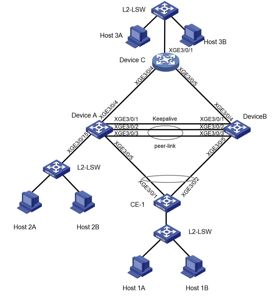
Network configuration
As shown in Figure 1:
· Device A and Device B form an M-LAG system.
· CE 1 is connected to the M-LAG system through the M-LAG interface.
· Device A and Device B are connected to uplink device Device C through equal-cost routes.
Customer challenges:
· Host-1A, Host-2A, and Host-3A belong to L3VPN instance VPNA and have dual-stack connectivity with each other.
· Host-1B, Host-2B, and Host-3B belong to L3VPN instance VPNB and have dual-stack connectivity with each other.
· When link failures occur on the M-LAG member devices, communications among Host-1A, Host-2A, and Host-3A and among Host-1B, Host-2B, and Host-3B are not affected.
|
Interface |
IP address |
Remarks |
|
|
Device A |
Loopback0 |
3.3.3.3/32 |
Loopback interface address. Router ID |
|
XGE 3/0/4 |
32.1.1.1/24 |
Device C: XGE 3/0/4 |
|
|
XGE 3/0/5 |
N/A |
CE-1: XGE3/0/1 M-LAG member interface. |
|
|
XGE 3/0/15 |
N/A |
Host-2A, Host-2B |
|
|
XGE 3/0/1 |
21.1.1.1/24 |
Device B: XGE 3/0/1 Keepalive interface. |
|
|
XGE 3/0/2 |
N/A |
Device B: XGE 3/0/2 M-LAG peer-link interface. |
|
|
XGE 3/0/3 |
N/A |
Device B: XGE 3/0/3 M-LAG peer-link interface. |
|
|
Vlan 101 |
101.1.1.1/24 |
Interface of the Layer 3 link connecting the two M-LAG member devices, which is used for forwarding east-west traffic or allowing north-south traffic to escape. |
|
|
Vlan-interface 1001 |
10.0.1.1/24 2000::10:0:1:1/112 |
VLAN interface the M-LAG interface of VPNA |
|
|
Vlan-interface 1002 |
10.1.1.1/24 2000::10:0:2:1/112 |
VLAN interface the single-homed interface of VPNA |
|
|
Vlan-interface 2001 |
20.0.1.1/24 2000::20:0:2:1/112 |
VLAN interface the M-LAG interface of VPNB |
|
|
Vlan-interface 2002 |
20.1.1.1/24 2000::20:0:2:1/112 |
VLAN interface the single-homed interface of VPNB |
|
|
Device B |
Loopback0 |
4.4.4.4/32 |
Loopback interface address. Router ID. |
|
XGE 3/0/4 |
33.1.1.1/24 |
Device C: XGE 3/0/5 |
|
|
XGE 3/0/5 |
N/A |
CE-1: XGE3/0/2 M-LAG member interface. |
|
|
XGE 3/0/1 |
21.1.1.2/24 |
Device A: XGE 3/0/1 Keepalive interface. |
|
|
XGE 3/0/2 |
N/A |
Device A: XGE 3/0/2 M-LAG peer-link interface. |
|
|
XGE 3/0/3 |
N/A |
Device A: XGE 3/0/3 M-LAG peer-link interface. |
|
|
Vlan 101 |
101.1.1.2/24 |
Interface of the Layer 3 link connecting the two M-LAG member devices, which is used for forwarding east-west traffic or allowing north-south traffic to escape. |
|
|
Vlan-interface 1001 |
10.0.1.1/24 2000::10:0:1:1/112 |
VLAN interface the M-LAG interface of VPNA |
|
|
Vlan-interface 2001 |
20.0.1.1/24 2000::20:0:1:1/112 |
VLAN interface the M-LAG interface of VPNB |
|
|
Device C |
Loopback0 |
5.5.5.5/32 |
Loopback interface address. Router ID. |
|
XGE 3/0/4 |
32.1.1.2/30 |
Device A: XGE3/0/4 |
|
|
XGE 3/0/5 |
33.1.1.2/30 |
Device B XGE3/0/4 |
|
|
XGE 3/0/1 |
N/A |
Host-3A, Host-3B |
|
|
Vlan-interface 1001 |
10.3.1.1/24 2000::10:3:1:1/112 |
VLAN interface for VPNA. |
|
|
Vlan-interface 2001 |
20.3.1.1/24 2000::20:3:1:1/112 |
VLAN interface for VPNB. |
|
|
CE-1 |
XGE 3/0/1 |
N/A |
Device A: XGE 3/0/5 |
|
XGE 3/0/2 |
N/A |
Device B XGE 3/0/5 |
|
|
XGE 3/0/15 |
N/A |
L2-LSW (connecting Host-1A and Host-1B) |
Applicable product matrix
In addition to running an applicable software version, you must also install the most recent patch, if any.
|
Device |
Software version |
|
S10500, S10500X, S7600, S7600-X, S7600E-X, S7500X, S7500E |
R7625 and later |
|
S12500G-AF (type T cards) |
R7625 and later |
|
S12500G-AF (type S cards) |
R8054P04 and later |
|
S10500X-G, S7500X-G |
R7754P04 and later |
|
S5590XP-HI-G, S6520X-EI-G, S6520XP-EI-G |
R7754P04 and later |
Analysis
· Device A and Device B form an M-LAG system.
· Device A and Device B are connected to uplink device Device C through equal-cost routes.
· Device A and Device B act as Layer 3 gateways for CE-side users. The gateway devices support dual-active and VRRP networking modes. This example uses the dual-active mode. For information about the VRRP mode, see the example for configuring an M-LAG + VRRP network (campus).
· The L3VPN network is configured with both IPv4 and IPv6 settings.
· Configure critical VLAN interfaces on the peer-link between Device A and Device B to implement Layer 3 connectivity. Then, packets sent from the local single-homed or M-LAG interface can be routed to the other M-LAG member device when the link between Device A or Device B and uplink device Device C fails.
Restrictions and guidelines
All devices in this example were started with the factory default configuration. When you are working on a live network, make sure you understand the potential impact of every command on your network.
Configuring IP addresses and unicast routing protocols
# On Host-1A, specify the gateway address as 10.0.1.1/2000::10:0:1:1. On Host-2A, specify the gateway address as 10.1.1.1/2000::10:1:1:1. On Host-3A, specify the gateway address as 10.3.1.1/2000::10:3:1:1.
# On Host-1B, specify the gateway address as 20.0.1.1/2000::20:0:1:1. On Host-2B, specify the gateway address 20.1.1.1/2000::20:1:1:1. On Host-3A, specify the gateway address as 20.3.1.1/2000::20:3:1:1.
# Configure OSPF on the IP core network to advertise routes for subnets attached to the interfaces (including Loopback interfaces) on each node. Make sure the switches have connectivity to each other.
Configuring the M-LAG member devices
Procedure summary
· Configuring the interconnect links between the M-LAG member devices and users
Configuring M-LAG
|
Device A |
Device B |
Description |
Remarks |
|
m-lag system-mac 2-2-2 |
m-lag system-mac 2-2-2 |
Set the MAC address of the M-LAG system. |
You must assign the same M-LAG system MAC address to the member devices in an M-LAG system. |
|
m-lag system-number 1 |
m-lag system-number 2 |
Set the M-LAG system number. |
You must assign different M-LAG system numbers to the member devices in an M-LAG system. |
|
m-lag system-priority 123 |
m-lag system-priority 123 |
Set the M-LAG system priority. |
You must set the same M-LAG system priority on the member devices in an M-LAG system. |
|
m-lag standalone enable |
m-lag standalone enable |
(Optional.) Enable standalone mode for the M-LAG devices. |
To avoid that two member devices both act the primary device after the M-LAG system splits, you can enable standalone mode before the M-LAG system splits. |
|
m-lag restore-delay 300 |
m-lag restore-delay 300 |
Configure the M-LAG latency. |
Set the maximum amount of time for the secondary M-LAG member device to synchronize data (such as MAC address entries) with the primary M-LAG member device during M-LAG system setup. |
|
m-lag keepalive ip destination 21.1.1.2 source 21.1.1.1 |
m-lag keepalive ip destination 21.1.1.1 source 21.1.1.2 |
Configure the source and destination IPv4 addresses of keepalive packets. |
N/A |
|
interface Ten-gigabitethernetE3/0/1 |
interface Ten-gigabitethernetE3/0/1 |
Enter the interface view for the keepalive link. |
N/A |
|
port link-mode route |
port link-mode route |
Configure the interface for the keepalive link to operate in route mode as a Layer 3 interface. |
N/A |
|
ip address 21.1.1.1 24 |
ip address 21.1.1.2 24 |
Configure the source IPv4 address of keepalive packets. |
N/A |
|
quit |
quit |
Return to system view. |
N/A |
|
m-lag mad exclude interface Ten-gigabitethernetE3/0/1 |
m-lag mad exclude interface Ten-gigabitethernetE3/0/1 |
Exclude the interface for the keepalive link from the shutdown action by M-LAG MAD. |
N/A |
|
interface bridge-aggregation 1 |
interface bridge-aggregation 1 |
Create an Ethernet aggregate interface. |
The interface is used as the peer link interface. |
|
link-aggregation mode dynamic |
link-aggregation mode dynamic |
Configure the aggregate interface to operate in dynamic mode. |
N/A |
|
quit |
quit |
Return to system view. |
N/A |
|
interface range Ten-gigabitethernetE 3/0/2 Ten-gigabitethernetE 3/0/3 |
interface range Ten-gigabitethernetE 3/0/2 Ten-gigabitethernetE 3/0/3 |
Enter physical interface range view. |
N/A |
|
port link-aggregation group 1 |
port link-aggregation group 1 |
Assign the physical interface for the peer link to the peer link aggregation group. |
N/A |
|
quit |
quit |
Return to system view. |
N/A |
|
interface bridge-aggregation 1 |
interface bridge-aggregation 1 |
Enter Ethernet aggregate interface view. |
N/A |
|
port m-lag peer-link 1 |
port m-lag peer-link 1 |
Specify the aggregate interface (Bridge-Aggregation 1) as the peer link interface. |
N/A |
|
undo mac-address static source-check enable |
undo mac-address static source-check enable |
Disable the static source check feature on the interface to avoid cross peer-link forwarding failure for traffic. |
N/A |
|
quit |
quit |
Return to system view. |
N/A |
|
lldp global enable |
lldp global enable |
Enable LLDP globally. |
N/A |
Configure IGP
|
Device A |
Device B |
Description |
Remarks |
|
router id 3.3.3.3 |
router id 4.4.4.4 |
Configure a router ID. |
N/A |
|
ospf 1 |
ospf 1 |
Enable OSPF |
N/A |
|
mpls ldp sync |
mpls ldp sync |
Configure LDP-OSPF synchronization. |
LDP establishes LSPs based on the IGP optimal routes. MPLS traffic forwarding might be interrupted if the actions of LDP and IGP are not synchronized. After LDP-IGP synchronization is enabled, IGP advertises the actual cost of a link only when LDP convergence on the link is completed. Before LDP convergence is completed, IGP advertises the maximum cost of the link. In this way, the link is visible on the IGP topology, but IGP does not select this link as the optimal route when other links are available. In this way, the device can avoid discarding MPLS packets when no LDP LSP is established on the optimal route. |
|
import-route direct |
import-route direct |
Redistribute direct routes in the OSPF process. |
N/A |
|
area 0 |
area 0 |
Create OSPF area 0. |
N/A |
|
quit |
quit |
Return to OSPF view. |
N/A |
|
Interface loopback 0 |
Interface loopback 0 |
Configure interface Loopback 0. |
N/A |
|
ip address 3.3.3.3 32 |
ip address 4.4.4.4 32 |
Configure the Loopback interface address. |
N/A |
|
ospf 1 area 0 |
ospf 1 area 0 |
Enable OSPF on the Loopback interface. |
N/A |
|
quit |
quit |
Return to system view. |
N/A |
|
interface Ten-gigabitethernetE 3/0/4 |
interface Ten-gigabitethernetE 3/0/4 |
Enter Ethernet interface view. |
N/A |
|
port link-mode route |
port link-mode route |
Configure the interface to operate in Layer 3 mode. |
N/A |
|
ip address 32.1.1.1 24 |
ip address 33.1.1.1 24 |
Configure an IPv4 address for the interface. |
N/A |
|
ospf 1 area 0 |
ospf 1 area 0 |
Enable OSPF on an interface. |
N/A |
|
ospf network-type p2p |
ospf network-type p2p |
Set the OSPF network type of the interface to P2P. |
N/A |
|
quit |
quit |
Return to system view. |
N/A |
|
vlan 101 |
vlan 101 |
Create VLAN 101. |
N/A |
|
quit |
quit |
Return to system view. |
N/A |
|
interface vlan-interface 101 |
interface vlan-interface 101 |
Create VLAN-interface 101. |
Interface of the Layer 3 link connecting the two M-LAG member devices, which is used for forwarding east-west traffic or allowing north-south traffic or Layer 3 remote mirroring traffic to escape. |
|
ip address 101.1.1.1 255.255.255.0 |
ip address 101.1.1.2 255.255.255.0 |
Assign an IPv4 address to VLAN-interface 101. |
N/A |
|
ospf 1 area 0 |
ospf 1 area 0 |
Enable OSPF on the interface. |
N/A |
|
ospf network-type p2p |
ospf network-type p2p |
Set the OSPF network type of the interface to P2P. |
N/A |
|
quit |
quit |
Return to system view. |
N/A |
|
m-lag mad exclude interface loopback 0 |
m-lag mad exclude interface loopback 0 |
Exclude all interfaces used by MPLS from the shutdown action by M-LAG MAD. |
N/A |
|
m-lag mad exclude interface Vlan-interface 101 |
m-lag mad exclude interface Vlan-interface 101 |
Exclude the VLAN interface from the shutdown action by M-LAG MAD. |
N/A |
Configuring MPLS L3VPN
|
Device A |
Device B |
Description |
Remarks |
|
mpls lsr-id 3.3.3.3 |
mpls lsr-id 4.4.4.4 |
Configure an MPLS LSR ID. |
N/A |
|
mpls ldp |
mpls ldp |
Enable LDP. |
N/A |
|
session protection |
session protection |
Configure session protection. |
If two LDP peers have both a direct link and an indirect link in between, you can configure this feature to protect their LDP session when the direct link fails. |
|
quit |
quit |
Return to system view. |
N/A |
|
Interface Ten-gigabitethernet 3/0/4 |
Interface Ten-gigabitethernet 3/0/4 |
Configure the interface interconnecting devices. |
N/A |
|
mpls enable |
mpls enable |
Enable MPLS on the interconnect interface. |
N/A |
|
mpls ldp enable |
mpls ldp enable |
Enable MPLS LDP on the interconnect interface. |
N/A |
|
quit |
quit |
Return to system view. |
N/A |
|
interface vlan-interface 101 |
interface vlan-interface 101 |
Enter the view of the critical VLAN interface for the M-LAG member interfaces. |
N/A |
|
mpls enable |
mpls enable |
Enable MPLS on the interconnect interface. |
N/A |
|
mpls ldp enable |
mpls ldp enable |
Enable MPLS LDP on the interconnect interface. |
N/A |
|
quit |
quit |
Return to system view. |
N/A |
|
ip vpn VPNA |
ip vpn VPNA |
Configure VPNA |
N/A |
|
route-distinguisher 100:1 |
route-distinguisher 100:1 |
Configure the RD. |
N/A |
|
vpn-target 100:1 |
vpn-target 100:1 |
Configure RTs. |
N/A |
|
quit |
quit |
Return to system view. |
N/A |
|
ip vpn VPNB |
ip vpn VPNB |
Configure VPNB. |
N/A |
|
route-distinguisher 100:2 |
route-distinguisher 100:2 |
Configure the RD. |
N/A |
|
vpn-target 100:2 |
vpn-target 100:2 |
Configure RTs. |
N/A |
|
quit |
quit |
Return to system view. |
N/A |
|
vlan 1001 to 1002 |
vlan 1001 |
Configure user VLANs for VPNA. |
N/A |
|
vlan 2001 to 2002 |
vlan 2001 |
Configure user VLANs for VPNB. |
N/A |
|
interface vlan-interface 1001 |
interface vlan-interface 1001 |
Configure the user VLAN interface for VPNA. |
N/A |
|
ip binding vpn-instance VPNA |
ip binding vpn-instance VPNA |
Bind VPNA to the interface. |
N/A |
|
ip address 10.0.1.1 24 |
ip address 10.0.1.1 24 |
Assign an IP address to the interface. |
N/A |
|
ipv6 address 2000::10:0:1:1 112 |
ipv6 address 2000::10:0:1:1 112 |
Assign an IPv6 address to the interface. |
N/A |
|
mac-address 1-1-1 |
mac-address 1-1-1 |
Configure the MAC address of the dual-active gateway. |
N/A |
|
quit |
quit |
Return to system view. |
N/A |
|
interface vlan-interface 2001 |
interface vlan-interface 2001 |
Configure the user VLAN interface for VPNB. |
N/A |
|
ip binding vpn-instance VPNB |
ip binding vpn-instance VPNB |
Bind VPNB to the interface. |
N/A |
|
ip address 20.0.1.1 24 |
ip address 20.0.1.1 24 |
Assign an IP address to the interface. |
N/A |
|
ipv6 address 2000::20:0:1:1 112 |
ipv6 address 2000::20:0:1:1 112 |
Assign an IPv6 address to the interface. |
N/A |
|
mac-address 1-1-2 |
mac-address 1-1-2 |
Configure the MAC address of the dual-active gateway. |
N/A |
|
quit |
quit |
Return to system view. |
N/A |
|
interface vlan-interface 1002 |
N/A |
Configure the single-homed user VLAN interface for VPNA. |
N/A |
|
ip binding vpn-instance VPNA |
N/A |
Bind VPNA to the interface. |
N/A |
|
ip address 10.1.1.1 24 |
N/A |
Assign an IP address to the interface. |
N/A |
|
ipv6 address 2000::10:1:1:1 112 |
N/A |
Assign an IPv6 address to the interface. |
N/A |
|
quit |
N/A |
Return to system view. |
N/A |
|
interface vlan-interface 2002 |
N/A |
Configure the single-homed user VLAN interface for VPNB. |
N/A |
|
ip binding vpn-instance VPNB |
N/A |
Bind VPNB to the interface. |
N/A |
|
ip address 20.1.1.1 24 |
N/A |
Assign an IP address to the interface. |
N/A |
|
ipv6 address 2000::20:1:1:1 112 |
N/A |
Assign an IPv6 address to the interface. |
N/A |
|
quit |
N/A |
Return to system view. |
N/A |
|
bgp 200 |
bgp 200 |
Enter BGP view. |
N/A |
|
peer 4.4.4.4 as-number 200 |
peer 3.3.3.3 as-number 200 |
Configure BGP peers |
BGP peer relationship between the two M-LAG member devices, which is used for forwarding east-west traffic or allowing north-south traffic to escape. |
|
peer 4.4.4.4 connect-interface loopback 0 |
peer 3.3.3.3 connect-interface loopback 0 |
Configure the interface connected to the BGP peer. |
N/A |
|
peer 5.5.5.5 as-number 200 |
peer 5.5.5.5 as-number 200 |
Configure BGP peers |
N/A |
|
peer 5.5.5.5 connect-interface loopback 0 |
peer 5.5.5.5 connect-interface loopback 0 |
Configure the interface connected to the BGP peer. |
N/A |
|
address-family vpnv4 |
address-family vpnv4 |
Enter VPNv4 view. |
N/A |
|
peer 4.4.4.4 enable |
peer 3.3.3.3 enable |
Establish an IPv4 MP-IBGP peer relationship between PEs. |
N/A |
|
peer 5.5.5.5 enable |
peer 5.5.5.5 enable |
Establish an IPv4 MP-IBGP peer relationship between PEs. |
N/A |
|
quit |
quit |
Return to BGP view. |
N/A |
|
address-family vpnv6 |
address-family vpnv6 |
Enter VPNv6 view. |
N/A |
|
peer 4.4.4.4 enable |
peer 3.3.3.3 enable |
Establish an IPv6 MP-IBGP peer relationship between PEs. |
N/A |
|
peer 5.5.5.5 enable |
peer 5.5.5.5 enable |
Establish an IPv6 MP-IBGP peer relationship between PEs. |
N/A |
|
quit |
quit |
Return to BGP view. |
N/A |
|
ip vpn-instance VPNA |
ip vpn-instance VPNA |
Enter VPNA instance view. |
N/A |
|
address-family ipv4 unicast |
address-family ipv4 unicast |
Enter IPv4 unicast address family view. |
N/A |
|
import-route direct |
import-route direct |
Import direct routes. |
N/A |
|
quit |
quit |
Return to VPNA instance view. |
N/A |
|
address-family ipv6 unicast |
address-family ipv6 unicast |
Enter IPv6 unicast address family view. |
N/A |
|
import-route direct |
import-route direct |
Import direct routes. |
N/A |
|
quit |
quit |
Return to VPNA instance view. |
N/A |
|
quit |
quit |
Return to BGP view. |
N/A |
|
ip vpn-instance VPNB |
ip vpn-instance VPNB |
Enter VPNA instance view. |
N/A |
|
address-family ipv4 unicast |
address-family ipv4 unicast |
Enter IPv4 unicast address family view. |
N/A |
|
import-route direct |
import-route direct |
Import direct routes. |
N/A |
|
quit |
quit |
Return to VPNB instance view. |
N/A |
|
address-family ipv6 unicast |
address-family ipv6 unicast |
Enter IPv6 unicast address family view. |
N/A |
|
import-route direct |
import-route direct |
Import direct routes. |
N/A |
|
quit |
quit |
Return to VPNB instance view. |
N/A |
|
quit |
quit |
Return to BGP view. |
N/A |
|
quit |
quit |
Return to system view. |
N/A |
Configuring the interconnect links between the M-LAG member devices and users
|
Device A |
Device B |
Description |
Remarks |
|
interface bridge-aggregation 2 |
interface bridge-aggregation 2 |
Create the Ethernet aggregate interface connecting to CE-1. |
N/A |
|
link-aggregation mode dynamic |
link-aggregation mode dynamic |
Configure the aggregate interface to operate in dynamic mode. |
N/A |
|
port m-lag group 1 |
port m-lag group 1 |
Assign the aggregate interface to M-LAG group 1. |
N/A |
|
port lacp system-priority 100 |
port lacp system-priority 101 |
Set the LACP priority. |
Ensure that when a brain split (simultaneous failure of keepalive link and peer link) occurs, only the member port with higher priority (the smaller the value, the higher the priority) is selected. |
|
quit |
quit |
Return to system view. |
N/A |
|
interface Ten-gigabitethernet 3/0/5 |
interface Ten-gigabitethernet 3/0/5 |
Enter the view of the physical interface connecting the M-LAG system to CE-1. |
N/A |
|
port link-aggregation group 2 |
port link-aggregation group 2 |
Assign the interfaces to an M-LAG group. |
N/A |
|
quit |
quit |
Return to system view. |
N/A |
|
interface bridge-aggregation 2 |
interface bridge-aggregation 2 |
Enter Ethernet aggregate interface view. |
N/A |
|
port link-type trunk |
port link-type trunk |
Configure the link type of the port as trunk. |
N/A |
|
port trunk permit vlan 1001 2001 |
port trunk permit vlan 1001 2001 |
Specify the VLANs permitted by the port. |
N/A |
|
quit |
quit |
Return to system view. |
N/A |
|
interface Ten-gigabitethernet 3/0/15 |
N/A |
Configure the single-homed interface. |
N/A |
|
port link-type trunk |
N/A |
Configure the link type of the port as trunk. |
N/A |
|
port trunk permit vlan 1002 2002 |
N/A |
Specify VLANs permitted by the port. |
N/A |
|
quit |
N/A |
Return to system view. |
N/A |
Configuring uplink device Device C
Procedure summary
· Configuring the downlinks towards users
Configure IGP
|
Device C |
Description |
Remarks |
|
router id 5.5.5.5 |
Configure a router ID. |
N/A |
|
ospf 1 |
Enable OSPF. |
N/A |
|
mpls ldp sync |
Configure LDP-OSPF synchronization. |
LDP establishes LSPs based on the optimal IGP routes. MPLS traffic forwarding interruption might occur because the actions of LDP and IGP are not synchronized. After LDP-IGP synchronization is enabled, IGP advertises the actual cost of a link only when LDP convergence on the link is completed. Before LDP convergence is completed, IGP advertises the maximum cost of the link. In this way, the link is visible on the IGP topology, but IGP does not select this link as the optimal route when other links are available. In this way, the device can avoid discarding MPLS packets when no LDP LSP is established on the optimal route. |
|
import-route direct |
Redistribute direct routes in the OSPF process. |
N/A |
|
area 0 |
Create OSPF area 0. |
N/A |
|
quit |
Return to OSPF view. |
N/A |
|
quit |
Return to system view. |
N/A |
|
interface Loopback 0 |
Configure the Loopback interface. |
N/A |
|
ip address 5.5.5.5 255,255,255,255 |
Assign an IPv4 address to the Loopback interface. |
N/A |
|
ospf 1 area 0.0.0.0 |
Enable OSPF on the Loopback interface. |
N/A |
|
quit |
Return to system view. |
N/A |
|
interface Ten-gigabitethernetE 3/0/4 |
Enter Ethernet interface view. |
N/A |
|
port link-mode route |
Configure the interconnect port to operate in Layer 3 mode. |
N/A |
|
ip address 32.1.1.1 24 |
Configure an IPv4 address for the interface. |
N/A |
|
ospf 1 area 0 |
Enable OSPF on an interface. |
N/A |
|
ospf network-type p2p |
Set the OSPF network type of the interface to P2P. |
N/A |
|
quit |
Return to system view. |
N/A |
|
interface Ten-gigabitethernetE 3/0/5 |
Enter Ethernet interface view. |
N/A |
|
port link-mode route |
Configure the interconnect port to operate in Layer 3 mode. |
N/A |
|
ip address 33.1.1.1 24 |
Configure an IPv4 address for the interface. |
N/A |
|
ospf 1 area 0 |
Enable OSPF on an interface. |
N/A |
|
ospf network-type p2p |
Set the OSPF network type of the interface to P2P. |
N/A |
|
quit |
Return to system view. |
N/A |
|
lldp global enable |
Enable LLDP globally |
N/A |
Configuring MPLS L3VPN
|
Device C |
Description |
Remarks |
|
mpls lsr-id 5.5.5.5 |
Configure an MPLS LSR ID. |
N/A |
|
mpls ldp |
Enable LDP. |
N/A |
|
session protection |
Configure session protection. |
If two LDP peers have both a direct link and an indirect link in between, you can configure this feature to protect their LDP session when the direct link fails. |
|
quit |
Return to system view. |
N/A |
|
Interface Ten-gigabitethernet 3/0/4 |
Configure the interface interconnecting devices. |
N/A |
|
mpls enable |
Enable MPLS on the interconnect interface. |
N/A |
|
mpls ldp enable |
Enable MPLS LDP on the interconnect interface. |
N/A |
|
quit |
Return to system view. |
N/A |
|
Interface Ten-gigabitethernet 3/0/5 |
Configure the interface interconnecting devices. |
N/A |
|
mpls enable |
Enable MPLS on the interconnect interface. |
N/A |
|
mpls ldp enable |
Enable MPLS LDP on the interconnect interface. |
N/A |
|
quit |
Return to system view. |
N/A |
|
ip vpn VPNA |
Configure VPNA |
N/A |
|
route-distinguisher 100:1 |
Configure the RD. |
N/A |
|
vpn-target 100:1 |
Configure RTs. |
N/A |
|
quit |
Return to system view. |
N/A |
|
ip vpn VPNB |
Configure VPNB. |
N/A |
|
route-distinguisher 100:2 |
Configure the RD. |
N/A |
|
vpn-target 100:2 |
Configure RTs. |
N/A |
|
quit |
Return to system view. |
N/A |
|
vlan 1001 |
Configure a user VLAN for VPNA. |
N/A |
|
vlan 2001 |
Configure a user VLAN for VPNB. |
N/A |
|
quit |
Return to system view. |
N/A |
|
interface vlan-interface 1001 |
Configure the user VLAN interface for VPNA. |
N/A |
|
ip binding vpn-instance VPNA |
Bind VPNA to the VLAN interface. |
N/A |
|
ip address 10.3.1.1 24 |
Assign an IP address to the interface. |
N/A |
|
ipv6 address 2000::10:3:1:1 112 |
Assign an IPv6 address to the interface. |
N/A |
|
quit |
Return to system view. |
N/A |
|
interface vlan-interface 2001 |
Configure the user VLAN interface for VPNB. |
N/A |
|
ip binding vpn-instance VPNB |
Bind VPNA to the VLAN interface. |
N/A |
|
ip address 20.3.1.1 24 |
Assign an IP address to the interface. |
N/A |
|
ipv6 address 2000::20:3:1:1 112 |
Assign an IPv6 address to the interface. |
N/A |
|
quit |
Return to system view. |
N/A |
|
bgp 200 |
Enter BGP view. |
N/A |
|
peer 3.3.3.3 as-number 200 |
Configure BGP peers |
N/A |
|
peer 3.3.3.3 connect-interface loopback 0 |
Configure the interface connected to the BGP peer. |
N/A |
|
peer 4.4.4.4 as-number 200 |
Configure BGP peers |
N/A |
|
peer 4.4.4.4 connect-interface loopback 0 |
Configure the interface connected to the BGP peer. |
N/A |
|
address-family vpnv4 |
Enter VPNv4 view. |
N/A |
|
peer 3.3.3.3 enable |
Establish an IPv4 MP-IBGP peer relationship between PEs. |
N/A |
|
peer 4.4.4.4 enable |
Establish an IPv4 MP-IBGP peer relationship between PEs. |
N/A |
|
quit |
Return to BGP view. |
N/A |
|
address-family vpnv6 |
Enter VPNv6 view. |
N/A |
|
peer 3.3.3.3 enable |
Establish an IPv6 MP-IBGP peer relationship between PEs. |
N/A |
|
peer 4.4.4.4 enable |
Establish an IPv6 MP-IBGP peer relationship between PEs. |
N/A |
|
quit |
Return to BGP view. |
N/A |
|
ip vpn-instance VPNA |
Enter VPNA view. |
N/A |
|
address-family ipv4 unicast |
Enter IPv4 unicast address family view. |
N/A |
|
balance 2 |
Enable load balancing and set the maximum number of routes for load balancing. |
N/A |
|
import-route direct |
Import direct routes. |
N/A |
|
quit |
Return to VPNA instance view. |
N/A |
|
address-family ipv6 unicast |
Enter IPv6 unicast address family view. |
N/A |
|
balance 2 |
Enable load balancing and set the maximum number of routes for load balancing. |
N/A |
|
import-route direct |
Import direct routes. |
N/A |
|
quit |
Return to VPNA instance view. |
N/A |
|
quit |
Return to BGP view. |
N/A |
|
ip vpn-instance VPNB |
Enter VPNB instance view. |
N/A |
|
address-family ipv4 unicast |
Enter IPv4 unicast address family view. |
N/A |
|
balance 2 |
Enable load balancing and set the maximum number of routes for load balancing. |
N/A |
|
import-route direct |
Import direct routes. |
N/A |
|
quit |
Return to VPNB instance view. |
N/A |
|
address-family ipv6 unicast |
Enter IPv6 unicast address family view. |
N/A |
|
balance 2 |
Enable load balancing and set the maximum number of routes for load balancing. |
N/A |
|
import-route direct |
Import direct routes. |
N/A |
|
quit |
Return to VPNB instance view. |
N/A |
|
quit |
Return to BGP view. |
N/A |
|
quit |
Return to system view. |
N/A |
Configuring the downlinks towards users
|
Device C |
Description |
Remarks |
|
interface Ten-gigabitethernet 3/0/1 |
Enter the view of the Ethernet interface connected to the user |
N/A |
|
port link-type trunk |
Configure the link type of the port as trunk. |
N/A |
|
port trunk permit vlan 1001 2001 |
Specify VLANs permitted by the port. |
N/A |
|
quit |
Return to system view. |
N/A |
Configuring access device CE-1
Procedure summary
· Configuring the interconnect links between the CE and M-LAG system
· Configuring the interconnect link between the CE and endpoints
Configuring the interconnect links between the CE and M-LAG system
|
CE-1 |
Description |
Remarks |
|
vlan 1001 |
Create a service VLAN. |
N/A |
|
vlan 2001 |
Create a service VLAN. |
N/A |
|
quit |
Return to system view. |
N/A |
|
interface bridge-aggregation 2 |
Create the Ethernet aggregate interface connecting to M-LAG. |
N/A |
|
link-aggregation mode dynamic |
Configure the aggregate interface to operate in dynamic mode. |
N/A |
|
quit |
Return to system view. |
N/A |
|
interface range Ten-gigabitethernet 3/0/1 to Ten-gigabitethernet 3/0/2 |
Enter the view of the physical interfaces connecting the CE to the M-LAG system. |
N/A |
|
port link-aggregation group 2 |
Add the interfaces to Ethernet aggregation group 2. |
N/A |
|
quit |
Return to system view. |
N/A |
|
interface bridge-aggregation 2 |
Enter Ethernet aggregate interface view. |
N/A |
|
port link-type trunk |
Configure the link type of the port as trunk. |
N/A |
|
port trunk permit vlan 1001 2001 |
Configure the aggregate interface to permit the specified VLANs. |
N/A |
|
quit |
Return to system view. |
N/A |
Configuring the interconnect link between the CE and endpoints
|
CE-1 |
Description |
Remarks |
|
interface Ten-gigabitethernet 3/015 |
Enter the view of the Ethernet interface connected to the endpoints. |
N/A |
|
port link-type trunk |
Configure the link type of the port as trunk. |
N/A |
|
port trunk permit vlan 1001 2001 |
Configure the aggregate interface to permit the specified VLANs. |
N/A |
|
quit |
Return to system view. |
N/A |
Traffic forwarding models
About the traffic model
The traffic model contains the following information:
· ID—Traffic ID, in O-X-XXX format. The first segment (O) represents overlay traffic. The second segment (X) represents the IP version (4 for IPv4 and 6 for IPv6). The third segment (XXX) represents a unique number for the traffic.
· Type—Traffic type, such as known unicast/IPv4 and unicast/L2.
· Direction—Traffic direction, such as inter M-LAG east-west traffic and north-west traffic.
· Path—The nodes that the traffic traverses from the source to the destination.
· Simulation method—Traffic simulation method. Testers are used to simulate the patterns of traffic on the network set up in this example.
· Simulation traffic load—The network can be tested under light load (fewer than 1000 simulation traffic flows) or heavy load (more than 1000 simulation traffic flows).
Traffic
|
ID |
Type |
Direction |
Path |
Simulation method |
Simulation traffic load |
Traffic direction to FW/LB |
Remarks |
|
O-4-001 |
Known unicast/IPv4 |
Across MPLS |
Host1-Device A/B-Device C-Host3 |
Tester |
Light |
N/A |
Traffic is forwarded over the Layer 3 link between the M-LAG member devices when the uplink fails. |
|
O-4-002 |
Known unicast/IPv4 |
Across MPLS |
Host2-Device A-Device C-Host3 |
Tester |
Light |
N/A |
|
|
O-6-001 |
Known unicast/IPv6 |
Across MPLS |
Host1-Device A/B-Device C-Host3 |
Tester |
Light |
N/A |
|
|
O-6-002 |
Known unicast/IPv6 |
Across MPLS |
Host2-Device A-Device C-Host3 |
Tester |
Light |
N/A |
Testing network convergence upon single points of failure
Failure test results
Table 1 Link failure test results
|
Device |
Failure type |
Traffic interruption time |
Remarks |
|
Device A |
Single M-LAG member link failure |
≤ 400 ms |
N/A |
|
Recovery from a single M-LAG member link failure |
≤ 100 ms |
N/A |
|
|
Single uplink failure |
≤ 400 ms |
N/A |
|
|
Recovery from a single uplink failure |
≤ 100 ms |
N/A |
|
|
Complete peer link failure |
≤ 400 ms |
Focus on M-LAG interface services. Single-homed interface services are not assured. |
|
|
Recovery from a complete peer link failure |
≤ 400 ms |
Focus on M-LAG interface services. Single-homed interface services can be restored. |
|
|
Keepalive link failure |
0 ms |
N/A |
|
|
Recovery from keepalive link failure |
0 ms |
N/A |
|
|
Recovery from a keepalive link and peer link failure |
≤ 30 s |
Focus on M-LAG interface services. Single-homed interface services are not assured. |
|
|
Recovery from a keepalive link and peer link failure |
≤ 2 s |
Focus on M-LAG interface services. Single-homed interface services can be restored. |
|
|
Restart one M-LAG member device. |
≤ 400 ms |
Focus on M-LAG interface services. Single-homed interface services are not assured. |
|
|
Recovery from M-LAG member device restart |
≤ 200 ms |
Focus on M-LAG interface services. Single-homed interface services can be restored. |
|
|
Switching fabric module failure |
≤ 100 ms |
N/A |
|
|
Recovery from a switching fabric module failure |
≤ 100 ms |
N/A |
Verifying the configuration
Commands
Table 2 Verification commands
|
Device A |
Device B |
Description |
|
display m-lag summary |
display m-lag summary |
Displays summary information about the IPP and DR interfaces in the DR system. |
|
display m-lag keepalive |
display m-lag keepalive |
Displays DR keepalive packet statistics. |
|
display m-lag role |
display m-lag role |
Displays DR role information. |
|
display m-lag verbose |
display m-lag verbose |
Displays detailed information about the peer-link interface and M-LAG interfaces. |
|
display mpls ldp lsp |
display mpls ldp lsp |
Displays LDP LSP information. |
|
display ip routing-table vpn-instance |
display ip routing-table vpn-instance |
Displays IPv4 routing information of a VPN instance. |
|
display ipv6 routing-table vpn-instance |
display ipv6 routing-table vpn-instance |
Displays IPv6 routing information of a VPN instance. |
Procedure
Verifying that the M-LAG system is operating correctly
Verify that the M-LAG system is set up correctly on Device A and Device B.
# Display summary information about the peer-link interface and M-LAG interfaces.
<Device A>display m-lag summary
Flags: A -- Aggregate interface down, B -- No peer M-LAG interface configured
C -- Configuration consistency check failed
Peer-link interface: BAGG1
Peer-link interface state (cause): UP
Keepalive link state (cause): UP
M-LAG interface information
M-LAG IF M-LAG group Local state (cause) Peer state Remaining down time(s)
BAGG2 1 UP UP -
<Device A>
<Device B>display m-lag summary
Flags: A -- Aggregate interface down, B -- No peer M-LAG interface configured
C -- Configuration consistency check failed
Peer-link interface: BAGG1
Peer-link interface state (cause): UP
Keepalive link state (cause): UP
M-LAG interface information
M-LAG IF M-LAG group Local state (cause) Peer state Remaining down time(s)
BAGG2 1 UP UP -
<Device B>
# Display M-LAG keepalive packet statistics and verify that the keepalive packet receive and send status is successful.
[Device A]display m-lag keepalive
Neighbor keepalive link status (cause): Up
Neighbor is alive for: 635 s 341 ms
Keepalive packet transmission status:
Sent: Successful
Received: Successful
Last received keepalive packet information:
Source IP address: 21.1.1.2
Time: 2022/08/04 09:54:33
Action: Accept
M-LAG keepalive parameters:
Destination IP address: 21.1.1.2
Source IP address: 21.1.1.1
Keepalive UDP port : 6400
Keepalive VPN name : N/A
Keepalive interval : 1000 ms
Keepalive timeout : 5 sec
Keepalive hold time: 3 sec
[Device A]
[Device B]display m-lag keepalive
Neighbor keepalive link status (cause): Up
Neighbor is alive for: 650 s 860 ms
Keepalive packet transmission status:
Sent: Successful
Received: Successful
Last received keepalive packet information:
Source IP address: 21.1.1.1
Time: 2022/08/04 09:59:42
Action: Accept
M-LAG keepalive parameters:
Destination IP address: 21.1.1.1
Source IP address: 21.1.1.2
Keepalive UDP port : 6400
Keepalive VPN name : N/A
Keepalive interval : 1000 ms
Keepalive timeout : 5 sec
Keepalive hold time: 3 sec
[Device B]
# Display M-LAG role information.
[Device A]display m-lag role
Effective role information
Factors Local Peer
Effective role Secondary Primary
Initial role Secondary Primary
MAD DOWN state Yes No
Health level 0 0
Role priority 32768 32768
Bridge MAC 0cda-41c5-aab0 0000-fc00-8d3c
Effective role trigger: Peer link calculation
Effective role reason: MAD status
Configured role information
Factors Local Peer
Configured role Secondary Primary
Role priority 32768 32768
Bridge MAC 0cda-41c5-aab0 0000-fc00-8d3c
[Device A]
[Device B]disp m-lag role
Effective role information
Factors Local Peer
Effective role Primary Secondary
Initial role Primary Secondary
MAD DOWN state No Yes
Health level 0 0
Role priority 32768 32768
Bridge MAC 0000-fc00-8d3c 0cda-41c5-aab0
Effective role trigger: Peer link calculation
Effective role reason: MAD status
Configured role information
Factors Local Peer
Configured role Primary Secondary
Role priority 32768 32768
Bridge MAC 0000-fc00-8d3c 0cda-41c5-aab0
[Device B]
# Display detailed information about the peer-link interface and M-LAG interfaces.
<Device A>display m-lag verbose
Flags: A -- Home_Gateway, B -- Neighbor_Gateway, C -- Other_Gateway,
D -- PeerLink_Activity, E -- DRCP_Timeout, F -- Gateway_Sync,
G -- Port_Sync, H -- Expired
Peer-link interface/Peer-link interface ID: BAGG1/1
State: UP
Cause: N/A
Local DRCP flags/Peer DRCP flags: ABDFG/ABDFG
Local Selected ports (index): XGE3/0/2 (292), XGE3/0/3 (293)
Peer Selected ports indexes: 292, 293
M-LAG interface/M-LAG group ID: BAGG2/1
Local M-LAG interface state: UP
Peer M-LAG interface state: UP
M-LAG group state: UP
Local M-LAG interface down cause: N/A
Remaining M-LAG DOWN time: N/A
Local M-LAG interface LACP MAC: Config=N/A, Effective=0002-0002-0002
Peer M-LAG interface LACP MAC: Config=N/A, Effective=0002-0002-0002
Local M-LAG interface LACP priority: Config=32768, Effective=123
Peer M-LAG interface LACP priority: Config=32768, Effective=123
Local DRCP flags/Peer DRCP flags: ABDFG/ABDFG
Local Selected ports (index): XGE3/0/5 (295)
Peer Selected ports indexes: 291
<Device B>disp m-lag verbose
Flags: A -- Home_Gateway, B -- Neighbor_Gateway, C -- Other_Gateway,
D -- PeerLink_Activity, E -- DRCP_Timeout, F -- Gateway_Sync,
G -- Port_Sync, H -- Expired
Peer-link interface/Peer-link interface ID: BAGG1/1
State: UP
Cause: N/A
Local DRCP flags/Peer DRCP flags: ABDFG/ABDFG
Local Selected ports (index): XGE3/0/2 (292), XGE3/0/3 (293)
Peer Selected ports indexes: 292, 293
M-LAG interface/M-LAG group ID: BAGG2/1
Local M-LAG interface state: UP
Peer M-LAG interface state: UP
M-LAG group state: UP
Local M-LAG interface down cause: -
Remaining M-LAG DOWN time: -
Local M-LAG interface LACP MAC: Config=N/A, Effective=0002-0002-0002
Peer M-LAG interface LACP MAC: Config=N/A, Effective=0002-0002-0002
Local M-LAG interface LACP priority: Config=32768, Effective=123
Peer M-LAG interface LACP priority: Config=32768, Effective=123
Local DRCP flags/Peer DRCP flags: ABDFG/ABDFG
Local Selected ports (index): XGE3/0/5 (295)
Peer Selected ports indexes: 291
<Device B>
Verifying LDP LSP information
# Display LDP peer and LDP session information on Device A.
[Device A]display mpls ldp peer
Total number of peers: 2
Peer LDP ID State Role GR MD5 KA Sent/Rcvd
5.5.5.5:0 Operational Passive Off Off 53/53
4.4.4.4:0 Operational Passive Off Off 48/48
[Device A]
# Display information about LSPs generated by LDP on Device A.
[Device A]display mpls ldp lsp
Status Flags: * - stale, L - liberal, B - backup, N/A - unavailable
FECs: 3 Ingress: 2 Transit: 2 Egress: 1
FEC In/Out Label Nexthop OutInterface/LSINDEX
3.3.3.3/32 3/-
-/1151(L)
-/1151(L)
4.4.4.4/32 -/3 101.1.1.2 Vlan101
1150/3 101.1.1.2 Vlan101
-/1150(L)
5.5.5.5/32 -/1150(L)
-/3 32.1.1.2 XGE3/0/4
1151/3 32.1.1.2 XGE3/0/4
[Device A]
# Display LDP peer and LDP session information on Device B.
[Device B]display mpls ldp peer
Total number of peers: 2
Peer LDP ID State Role GR MD5 KA Sent/Rcvd
3.3.3.3:0 Operational Active Off Off 51/51
5.5.5.5:0 Operational Passive Off Off 51/51
[Device B]
# Display information about LSPs generated by LDP on Device B.
[Device B]display mpls ldp lsp
Status Flags: * - stale, L - liberal, B - backup, N/A - unavailable
FECs: 3 Ingress: 2 Transit: 2 Egress: 1
FEC In/Out Label Nexthop OutInterface/LSINDEX
3.3.3.3/32 -/3 101.1.1.1 Vlan101
1151/3 101.1.1.1 Vlan101
-/1151(L)
4.4.4.4/32 3/-
-/1150(L)
-/1150(L)
5.5.5.5/32 -/1151(L)
-/3 33.1.1.2 XGE3/0/4
1150/3 33.1.1.2 XGE3/0/4
[Device B]
# Display LDP peer and LDP session information on Device C.
[Device C]display mpls ldp peer
Total number of peers: 2
Peer LDP ID State Role GR MD5 KA Sent/Rcvd
3.3.3.3:0 Operational Active Off Off 58/58
4.4.4.4:0 Operational Active Off Off 53/53
[Device C]
# Display information about LSPs generated by LDP on Device C.
[Device C]display mpls ldp lsp
Status Flags: * - stale, L - liberal, B - backup
FECs: 3 Ingress: 2 Transit: 2 Egress: 1
FEC In/Out Label Nexthop OutInterface
3.3.3.3/32 -/3 32.1.1.1 XGE3/0/4
1151/3 32.1.1.1 XGE3/0/4
-/1151(L)
4.4.4.4/32 -/1150(L)
-/3 33.1.1.1 XGE3/0/5
1150/3 33.1.1.1 XGE3/0/5
5.5.5.5/32 3/-
-/1151(L)
-/1150(L)
[Device C]display mpls ldp peer
Total number of peers: 2
Peer LDP ID State Role GR MD5 KA Sent/Rcvd
3.3.3.3:0 Operational Active Off Off 58/58
4.4.4.4:0 Operational Active Off Off 53/53
[Device C]
[Device C]display mpls ldp lsp
Status Flags: * - stale, L - liberal, B - backup
FECs: 3 Ingress: 2 Transit: 2 Egress: 1
FEC In/Out Label Nexthop OutInterface
3.3.3.3/32 -/3 32.1.1.1 XGE3/0/4
1151/3 32.1.1.1 XGE3/0/4
-/1151(L)
4.4.4.4/32 -/1150(L)
-/3 33.1.1.1 XGE3/0/5
1150/3 33.1.1.1 XGE3/0/5
5.5.5.5/32 3/-
-/1151(L)
-/1150(L)
Verifying IPv4 routing information of VPN instances
# Display IPv4 routing information of the VPN instances on Device A.
[Device A]display ip routing-table vpn-instance VPNA protocol bgp
Summary count : 1
BGP Routing table status : <Active>
Summary count : 1
Destination/Mask Proto Pre Cost NextHop Interface
10.3.1.0/24 BGP 255 0 5.5.5.5 XGE3/0/4
BGP Routing table status : <Inactive>
Summary count : 0
[Device A]
[Device A]display ip routing-table vpn-instance VPNB protocol bgp
Summary count : 1
BGP Routing table status : <Active>
Summary count : 1
Destination/Mask Proto Pre Cost NextHop Interface
20.3.1.0/24 BGP 255 0 5.5.5.5 XGE3/0/4
BGP Routing table status : <Inactive>
Summary count : 0
[Device A]
# Display IPv4 routing information of the VPN instances on Device B.
[Device B]display ip routing-table vpn-instance VPNA protocol bgp
Summary count : 2
BGP Routing table status : <Active>
Summary count : 2
Destination/Mask Proto Pre Cost NextHop Interface
10.1.1.0/24 BGP 255 0 3.3.3.3 Vlan101
10.3.1.0/24 BGP 255 0 5.5.5.5 XGE2/0/9
BGP Routing table status : <Inactive>
Summary count : 0
[Device B]display ip routing-table vpn-instance VPNB protocol bgp
Summary count : 2
BGP Routing table status : <Active>
Summary count : 2
Destination/Mask Proto Pre Cost NextHop Interface
20.1.1.0/24 BGP 255 0 3.3.3.3 Vlan101
20.3.1.0/24 BGP 255 0 5.5.5.5 XGE2/0/9
BGP Routing table status : <Inactive>
Summary count : 0
[Device B]
# Display IPv4 routing information of the VPN instances on Device C.
[Device C]display ip routing-table vpn-instance VPNA protocol bgp
Summary count : 3
BGP Routing table status : <Active>
Summary count : 3
Destination/Mask Proto Pre Cost NextHop Interface
10.0.1.0/24 BGP 255 0 3.3.3.3 XGE1/0/2
4.4.4.4 XGE1/0/3
10.1.1.0/24 BGP 255 0 3.3.3.3 XGE1/0/2
BGP Routing table status : <Inactive>
Summary count : 0
[Device C]display ip routing-table vpn-instance VPNB protocol bgp
Summary count : 3
BGP Routing table status : <Active>
Summary count : 3
Destination/Mask Proto Pre Cost NextHop Interface
20.0.1.0/24 BGP 255 0 3.3.3.3 XGE1/0/2
4.4.4.4 XGE1/0/3
20.1.1.0/24 BGP 255 0 3.3.3.3 XGE1/0/2
BGP Routing table status : <Inactive>
Summary count : 0
[Device C]
Verifying IPv6 routing information of VPN instances
# Display IPv6 routing information of the VPN instances on Device A.
[Device A]display ipv6 routing-table vpn-instance VPNA protocol bgp
Summary count : 1
BGP4+ Routing table status : <Active>
Summary count : 1
Destination: 2000::10:3:1:0/112 Protocol : BGP4+
NextHop : ::FFFF:5.5.5.5 Preference: 255
Interface : XGE3/0/4 Cost : 0
BGP4+ Routing table status : <Inactive>
Summary count : 0
[Device A]
[Device A]display ipv6 routing-table vpn-instance VPNB protocol bgp
Summary count : 1
BGP4+ Routing table status : <Active>
Summary count : 1
Destination: 2000::20:3:1:0/112 Protocol : BGP4+
NextHop : ::FFFF:5.5.5.5 Preference: 255
Interface : XGE3/0/4 Cost : 0
BGP4+ Routing table status : <Inactive>
Summary count : 0
[Device A]
# Display IPv6 routing information of the VPN instances on Device B.
[Device B]display ipv6 routing-table vpn-instance VPNA protocol bgp
Summary count : 2
BGP4+ Routing table status : <Active>
Summary count : 2
Destination: 2000::10:1:1:0/112 Protocol : BGP4+
NextHop : ::FFFF:3.3.3.3 Preference: 255
Interface : Vlan101 Cost : 0
Destination: 2000::10:3:1:0/112 Protocol : BGP4+
NextHop : ::FFFF:5.5.5.5 Preference: 255
Interface : XGE2/0/9 Cost : 0
BGP4+ Routing table status : <Inactive>
Summary count : 0
[Device B]display ipv6 routing-table vpn-instance VPNB protocol bgp
Summary count : 2
BGP4+ Routing table status : <Active>
Summary count : 2
Destination: 2000::20:1:1:0/112 Protocol : BGP4+
NextHop : ::FFFF:3.3.3.3 Preference: 255
Interface : Vlan101 Cost : 0
Destination: 2000::20:3:1:0/112 Protocol : BGP4+
NextHop : ::FFFF:5.5.5.5 Preference: 255
Interface : XGE2/0/9 Cost : 0
BGP4+ Routing table status : <Inactive>
Summary count : 0
[Device B]
# Display IPv6 routing information of the VPN instances on Device C.
[Device C]display ipv6 routing-table vpn-instance VPNA protocol bgp
Summary count : 3
BGP4+ Routing table status : <Active>
Summary count : 3
Destination: 2000::10:0:1:0/112 Protocol : BGP4+
NextHop : ::FFFF:3.3.3.3 Preference: 255
Interface : XGE1/0/2 Cost : 0
Destination: 2000::10:0:1:0/112 Protocol : BGP4+
NextHop : ::FFFF:4.4.4.4 Preference: 255
Interface : XGE1/0/3 Cost : 0
Destination: 2000::10:1:1:0/112 Protocol : BGP4+
NextHop : ::FFFF:3.3.3.3 Preference: 255
Interface : XGE1/0/2 Cost : 0
BGP4+ Routing table status : <Inactive>
Summary count : 0
[Device C]display ipv6 routing-table vpn-instance VPNB protocol bgp
Summary count : 3
BGP4+ Routing table status : <Active>
Summary count : 3
Destination: 2000::20:0:1:0/112 Protocol : BGP4+
NextHop : ::FFFF:3.3.3.3 Preference: 255
Interface : XGE1/0/2 Cost : 0
Destination: 2000::20:0:1:0/112 Protocol : BGP4+
NextHop : ::FFFF:4.4.4.4 Preference: 255
Interface : XGE1/0/3 Cost : 0
Destination: 2000::20:1:1:0/112 Protocol : BGP4+
NextHop : ::FFFF:3.3.3.3 Preference: 255
Interface : XGE1/0/2 Cost : 0
BGP4+ Routing table status : <Inactive>
Summary count : 0
[Device C]
Verifying host communication
Host 1A/Host2A and Host 3A can communicate with each other at dual stacks, and the same with Host 1B/Host 2B and Host 3B.
Verifying host communication in case of Device A or Device B downlink M-LAG member interface failure
Host 1A/Host 2A and Host 3A can still communicate with each other, and the same with Host 1B/Host 2B and Host 3B.
Verifying host communication in case of Device A or Device B uplink interface failure
Disconnect Device A from Device C. Verify that Host 1A/Host 2A and Host 3A can still communicate with each other, and the same with Host 1B/Host 2B and Host 3B. (After Device A is disconnected from Device C, traffic accessing Device A is switched to Device B for forwarding through the interconnect links between the two devices. Transient packet loss occurs during the traffic switchover process.)
Disconnect Device B from Device C. Verify that Host 1A/Host 2A and Host 3A can still communicate with each other, and the same with Host 1B/Host 2B and Host 3B. (After Device B is disconnected from Device C, traffic accessing Device B is switched to Device A for forwarding through the interconnect links between the two devices. Transient packet loss occurs during the traffic switchover process.)
Upgrade procedure
Pre-upgrade verification commands
Before you perform an upgrade, use the commands in Verifying the configuration and the commands in the following table to verify that all requirements are met for an upgrade.
Table 3 Pre-upgrade verification commands
|
Device A |
Device B |
Description |
|
display device |
display device |
Displays summary information about the peer link interfaces and M-LAG interfaces in the M-LAG system. |
|
display boot-loader |
display boot-loader |
Displays the current software images and startup software images. |
|
display version |
display version |
Displays system version information. |
Upgrade procedure
Before you upgrade the device software, perform the following tasks:
1. Execute the display version command to verify the current BootWare image version and startup software version.
2. Use the release notes for the upgrade software version to evaluate the upgrade impact on your network and verify the following items:
¡ Software and hardware compatibility.
¡ Version and size of the upgrade software.
¡ Compatibility of the upgrade software with the current BootWare image and startup software image.
3. Use the release notes to verify whether the upgrade software images require a license. If licenses are required, check the system for availability of valid licenses. If no license exists on the device, first install a license. If you do not install a license, the software package will fail to be installed.
4. Use the dir command to verify that the device has sufficient storage space for the upgrade images. If the storage space is not sufficient, delete unused files by using the delete command. Make sure that all MPUs in the system have sufficient storage space.
5. After Device A and Device B form an M-LAG system, perform the following tasks:
a. Check the LLDP neighbors of Device A to obtain the LLDP state information of all interfaces on Device A.
b. Manually shut down all interfaces connecting to the other devices (except the peer-link and keepalive interfaces) on Device A to
c. Switch all incoming and outgoing traffic of Device A to Device B.
6. Save the configuration on Device A, and use FTP or TFTP to transfer the upgrade image file to the root directory of a file system. Upgrade Device A and reboot it.
7. When Device A is being rebooted, manually shut down the interconnect interfaces connecting Device B to Device A, typically the peer-link and keepalive interfaces.
8. After Device A is rebooted, bring up the interfaces that have been shut down on Device B. Wait for M-LAG to restore between Device A and Device B.
9. After Device A and Device B form a new M-LAG system again, bring up the interfaces connecting to the other devices. Wait for the traffic to restore.
For the detailed upgrade guide, see H3C Switches M-LAG System Upgrade Guide.
Upgrade the software. For more information about the software upgrade procedure, see the fundamentals configuration guide for the device.
Estimating upgrade downtime
See “Testing network convergence upon single points of failure.” The upgrade downtime of each device contains the traffic downtime for restart of one M-LAG member device and recovery from M-LAG member device restart.
Verifying the upgrade result
Execute the commands in "Verifying the configuration" and the following commands to verify that the device is upgraded successfully.
Table 4 Post-upgrade verification commands
|
Device A |
Device B |
Description |
|
display device |
display device |
Displays summary information about the peer link interfaces and M-LAG interfaces in the M-LAG system. |
|
display boot-loader |
display boot-loader |
Displays the current software images and startup software images. |
|
display version |
display version |
Displays system version information. |
Expanding the network
Pre-expansion verification commands
Execute the commands in “Verifying the configuration" and the following commands to verify that the device is available for an expansion.
Table 5 Pre-expansion verification commands
|
Device A |
Device B |
Description |
|
display device |
display device |
Displays summary information about the peer link interfaces and M-LAG interfaces in the M-LAG system. |
|
display boot-loader |
display boot-loader |
Displays the current software images and startup software images. |
|
display version |
display version |
Displays system version information. |
Expanding the network
1. Make sure the expansion device is not connected to the management network.
2. Upgrade the device to the target software version.
3. Configure the device.
4. Connect the device to the management network.
Estimating expansion downtime
N/A
Verifying the expansion result
After the expansion finishes, use the commands in the following table to verify that the expansion has been done correctly.
Table 6 Post-expansion verification commands
|
Device A |
Device B |
Description |
|
display device |
display device |
Displays summary information about the peer link interfaces and M-LAG interfaces in the M-LAG system. |
|
display boot-loader |
display boot-loader |
Displays the current software images and startup software images. |
|
display version |
display version |
Displays system version information. |
Replacing hardware
Replacing a service module
Pre-replacement verification commands
Execute the commands in “Verifying the configuration" and the following commands to verify that the target device is available for a replacement.
Table 7 Command check summary before replacement
|
Device A |
Device B |
Description |
|
display device |
display device |
Displays device information. |
|
display boot-loader |
display boot-loader |
Displays the current software images and startup software images. |
|
display version |
display version |
Displays system version information. |
Replacing hardware
Before you replace an interface module, make sure the service and management traffic has switched over to other interface modules that are operating correctly.
Replace the interface modules online while the system is operating or power off the system before you do the replacement, depending on the evaluation of the conditions.
Verifying the traffic interruption time
See “Testing network convergence upon single points of failure.” The replacement downtime of each interface module contains the traffic downtime for single member link failure in an M-LAG interface, single uplink failure, recovery from a single member link failure in an M-LAG interface, and recovery from a single uplink failure.
Verifying the replacement result
Use the same commands for pre-replacement verification to verify that the system can operate correctly after the hardware replacement.
Replacing a switching fabric module
Pre-replacement verification commands
Execute the commands in "Verifying the configuration" and the following commands to verify that the target device is available for a replacement.
Table 8 Command check summary before replacement
|
Device A |
Device B |
Description |
|
display device |
display device |
Displays summary information about the peer link interfaces and M-LAG interfaces in the M-LAG system. |
|
display boot-loader |
display boot-loader |
Displays the current software images and startup software images. |
|
display version |
display version |
Displays system version information. |
Replacing hardware
Power off the device and replace the switching fabric module, or replace the switching fabric module when the device is running. For more information, see the installation guides for the switching fabric module.
Verifying the traffic interruption time
See “Testing network convergence upon single points of failure.” The replacement downtime of each switching fabric module contains the traffic downtime for switching fabric module failure and recovery from a switching fabric module failure.
Verifying the replacement result
Use the same commands for pre-replacement verification to verify that the system can operate correctly after the hardware replacement.
