- Table of Contents
-
- H3C Campus Switches M-LAG Configuration Guide-6W101
- 00-M-LAG network planning for campus networks
- 01-M-LAG and VRRP Configuration Example (Campus)
- 02-M-LAG + Spanning Tree Configuration Example (Campus)
- 03-Dual-Active VLAN Gateway Configuration Example (Campus)
- 04-M-LAG and Loop Detection Configuration Example (Campus)
- 05-Multi-Tier M-LAG and VRRP Configuration Example (Campus)
- 06-M-LAG + VXLAN Distributed Gateway Network Configuration Example (Ethernet Aggregate Link as Peer Link) (Campus)
- 07-M-LAG + EVPN VXLAN Centralized Gateway Network Configuration Example (Ethernet Aggregate Link as Peer Link) (Campus)
- 08-M-LAG and MPLS L3VPN Configuraion Example (Campus)
- 09-M-LAG and Mirroring Configuration Example (Campus)
- Related Documents
-
| Title | Size | Download |
|---|---|---|
| 04-M-LAG and Loop Detection Configuration Example (Campus) | 245.94 KB |
Example: Configuring M-LAG and loop detection
Configuring the interconnect links between the M-LAG system and Device C/Device D
Configuring the interconnect links between Device C/Device D and the LAG devices
Configuring the interconnect links between Device C/Device D and Device E
Disabling the spanning tree feature globally on Device C/Device D
Configuring the interconnect links between Device E and Device C/Device D
Disabling the spanning tree feature globally on Device E
Convergence performance test results
Pre-upgrade verification commands
Post-upgrade verification commands
Pre-expansion verification commands
Post-expansion verification commands
Switching fabric module replacement
Example: Configuring M-LAG and loop detection
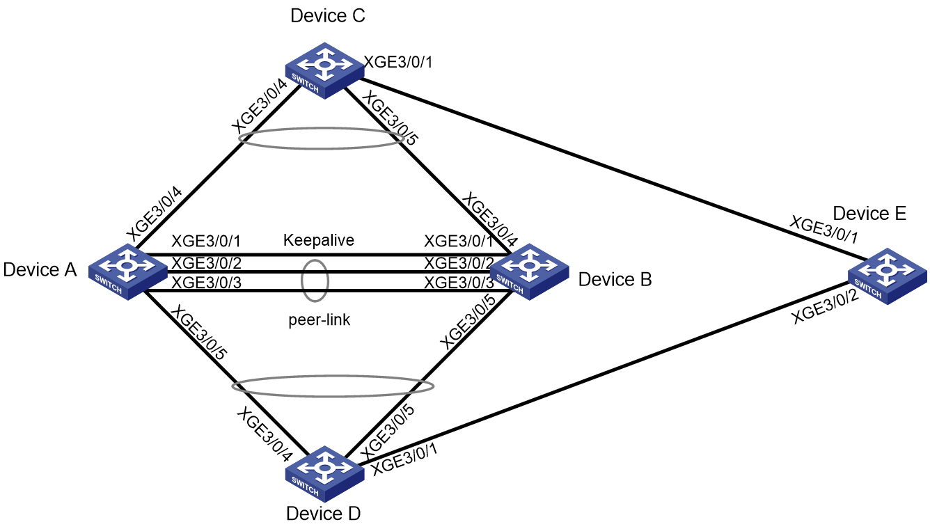
Network configuration
As shown in Figure 1:
· Device A and Device B form an M-LAG system. Device C and Device D access the M-LAG system through M-LAG interfaces.
· Device E is connected to Device C and Device D.
Configure loop detection on the M-LAG system to meet the following requirements:
· Automatically shuts down the interface on which
a loop is detected.
Generates a log as a notification.
|
Device |
Interface |
IP address |
Remarks |
|
Device A |
XGE 3/0/4 |
N/A |
Device C: XGE 3/0/4 The interface is used as the M-LAG interface. |
|
XGE 3/0/5 |
N/A |
Device ID: XGE 3/0/4 The interface is used as the M-LAG interface |
|
|
XGE 3/0/1 |
21.1.1.1/24 |
Device B: XGE 3/0/1 The interface is used as the keepalive interface. |
|
|
XGE 3/0/2 |
N/A |
Device B: XGE 3/0/2 The interface is used as the peer-link interface. |
|
|
XGE 3/0/3 |
N/A |
Device B: XGE 3/0/3 The interface is used as the peer-link interface. |
|
|
Device B |
XGE 3/0/4 |
N/A |
Device C: XGE 3/0/5 The interface is used as the M-LAG interface |
|
XGE 3/0/5 |
N/A |
Device ID: XGE 3/0/5 The interface is used as the M-LAG interface |
|
|
XGE 3/0/1 |
21.1.1.2/24 |
Device A: XGE 3/0/1 The interface is used as the keepalive interface. |
|
|
XGE 3/0/2 |
N/A |
Device A: XGE 3/0/2 The interface is used as the peer-link interface. |
|
|
XGE 3/0/3 |
N/A |
Device A: XGE 3/0/3 The interface is used as the peer-link interface. |
|
|
Device C |
XGE 3/0/4 |
N/A |
Device A: XGE 3/0/4 |
|
XGE 3/0/5 |
N/A |
Device B: XGE 3/0/4 |
|
|
XGE 3/0/1 |
N/A |
Device E: XGE 3/0/1 |
|
|
Device D |
XGE 3/0/4 |
N/A |
Device A: XGE 3/0/5 |
|
XGE 3/0/5 |
N/A |
Device B: XGE 3/0/5 |
|
|
XGE 3/0/1 |
N/A |
Device E: XGE 3/0/2 |
|
|
Device E |
XGE 3/0/1 |
N/A |
Device C: XGE 3/0/1 |
|
XGE 3/0/2 |
N/A |
Device D: XGE 3/0/1 |
Applicable product matrix
|
|
IMPORTANT: In addition to running an applicable software version, you must also install the most recent patch, if any. |
|
Device |
Software version |
|
S10500, S10500X, S7600, S7600-X, S7600E-X, S7500X, S7500E |
R7625 and later |
|
S12500G-AF (type T cards) |
R7625 and later |
|
S12500G-AF (type S cards) |
R8054P04 and later |
|
S10500X-G, S7500X-G |
R7754P04 and later |
|
S5590XP-HI-G, S6520X-EI-G, S6520XP-EI-G |
R7754P04 and later |
|
S6550XE-HI, S6525XE-HI |
R8106P22 and later |
|
S6520X-EI, S6520X-HI |
F6628P11 and later |
|
S5590-HI, S5590-EI, S6805-G, S6850-G, S6530X, S9850-G |
R8307P08 and later |
|
S5560X-HI |
F6628P11 and later |
|
S5560X-EI |
F6628P11 and later |
Analysis
· Configure Device A and Device B to form an M-LAG system. Assign the uplink interfaces to an M-LAG group connecting to Device C, and the downlink interfaces to another M-LAG group connecting to Device D.
· Enable loop detection on Device A and Device B.
· Disable the spanning tree feature globally.
Restrictions and guidelines
All the devices were started with the factory default configuration. When you are working on a live network, make sure you understand the potential impact of every command on your network.
Configure the M-LAG devices
Procedure summary
· Configuring the interconnect links between the M-LAG system and Device C/Device D
Configuring M-LAG
|
Device A |
Device B |
Description |
Remarks |
|
m-lag system-mac 2-2-2 |
m-lag system-mac 2-2-2 |
Set the MAC address of the M-LAG system. |
You must assign the same M-LAG system MAC address to the member devices in an M-LAG system. |
|
m-lag system-number 1 |
m-lag system-number 2 |
Set the M-LAG system number. |
You must assign different M-LAG system numbers to the member devices in an M-LAG system. |
|
m-lag system-priority 123 |
m-lag system-priority 123 |
Set the M-LAG system priority. |
You must set the same M-LAG system priority on the member devices in an M-LAG system. |
|
m-lag standalone enable |
m-lag standalone enable |
(Optional.) Enable standalone mode for the M-LAG devices. |
To avoid that two member devices both act the primary device after the M-LAG system splits, you can enable standalone mode before the M-LAG system splits. |
|
m-lag keepalive ip destination 21.1.1.2 source 21.1.1.1 |
m-lag keepalive ip destination 21.1.1.1 source 21.1.1.2 |
Configure the source and destination IPv4 addresses of keepalive packets. |
N/A |
|
interface Ten-gigabitethernet3/0/1 |
interface Ten-gigabitethernet3/0/1 |
Enter the interface view for the keepalive link. |
N/A |
|
port link-mode route |
port link-mode route |
Configure the interface for keepalive detection to operate in route mode as a Layer 3 interface. |
N/A |
|
ip address 21.1.1.1 24 |
ip address 21.1.1.2 24 |
Configure the source IPv4 address of keepalive packets. |
N/A |
|
quit |
quit |
Return to system view. |
N/A |
|
m-lag mad exclude interface Ten-gigabitethernet3/0/1 |
m-lag mad exclude interface Ten-gigabitethernet3/0/1 |
Exclude the keepalive interface from the shutdown action by M-LAG MAD. |
N/A |
|
interface bridge-aggregation 1 |
interface bridge-aggregation 1 |
Create an Ethernet aggregate interface. |
The interface is used as the peer link interface. |
|
link-aggregation mode dynamic |
link-aggregation mode dynamic |
Configure the aggregate interface to operate in dynamic mode. |
N/A |
|
quit |
quit |
Return to system view. |
N/A |
|
interface range Ten-gigabitethernet 3/0/2 Ten-gigabitethernet 3/0/3 |
interface range Ten-gigabitethernet 3/0/2 Ten-gigabitethernet 3/0/3 |
Enter the view of the physical interface for the peer link. |
N/A |
|
port link-aggregation group 1 |
port link-aggregation group 1 |
Assign the physical interface for the peer link to the peer link aggregation group. |
N/A |
|
quit |
quit |
Return to system view. |
N/A |
|
interface bridge-aggregation 1 |
interface bridge-aggregation 1 |
Enter Ethernet aggregate interface view. |
N/A |
|
port m-lag peer-link 1 |
port m-lag peer-link 1 |
Specify the aggregate interface (Bridge-Aggregation 1) as the peer link interface. |
N/A |
|
undo mac-address static source-check enable |
undo mac-address static source-check enable |
Disable the static source check feature on the interface to avoid cross peer-link forwarding failure for traffic. |
N/A |
|
quit |
quit |
Return to system view. |
N/A |
Configuring the interconnect links between the M-LAG system and Device C/Device D
|
Device A |
Device B |
Description |
Remarks |
|
interface bridge-aggregation 4 |
interface bridge-aggregation 4 |
Create the Ethernet aggregate interface connecting to Device C. |
N/A |
|
link-aggregation mode dynamic |
link-aggregation mode dynamic |
Configure the aggregate interface to operate in dynamic mode. |
N/A |
|
port m-lag group 4 |
port m-lag group 4 |
Assign the aggregate interface (Bridge-Aggregation 4) to M-LAG group 4. |
N/A |
|
quit |
quit |
Return to system view. |
N/A |
|
interface Ten-gigabitethernet 3/0/4 |
interface Ten-gigabitethernet 3/0/4 |
Enter the view of the physical interfaces connecting the M-LAG system to Device C. |
N/A |
|
port link-aggregation group 4 |
port link-aggregation group 4 |
Assign interfaces to an aggregation group. |
N/A |
|
quit |
quit |
Return to system view. |
N/A |
|
interface bridge-aggregation 5 |
interface bridge-aggregation 5 |
Create the Ethernet aggregate interface connecting to Device D. |
N/A |
|
link-aggregation mode dynamic |
link-aggregation mode dynamic |
Configure the aggregate interface to operate in dynamic mode. |
N/A |
|
port m-lag group 5 |
port m-lag group 5 |
Assign the aggregate interface (Bridge-Aggregation 5) to M-LAG group 5. |
N/A |
|
quit |
quit |
Return to system view. |
N/A |
|
interface Ten-gigabitethernet 3/0/5 |
interface Ten-gigabitethernet 3/0/5 |
Enter the view of the physical interfaces connecting the LAG system to Device D. |
N/A |
|
port link-aggregation group 5 |
port link-aggregation group 5 |
Assign interfaces to an aggregation group. |
N/A |
|
quit |
quit |
Return to system view. |
N/A |
|
vlan 100 |
vlan 100 |
Create a VLAN. |
N/A |
|
quit |
quit |
Return to system view. |
N/A |
|
interface range bridge-aggregation 4 bridge-aggregation 5 |
interface range bridge-aggregation 4 bridge-aggregation 5 |
Enter the view of the Ethernet aggregate interface range. |
N/A |
|
port link-type trunk |
port link-type trunk |
Set the link type of the Layer 2 aggregate interface (Bridge-Aggregation 4 and Bridge-Aggregation 5) to trunk. |
N/A |
|
port trunk permit vlan 100 |
port trunk permit vlan 100 |
Assign the interface to VLAN 100. |
N/A |
|
undo port trunk permit vlan 1 |
undo port trunk permit vlan 1 |
Remove the interface from VLAN 1. |
N/A |
|
port lacp system-priority 100 |
port lacp system-priority 101 |
Set the LACP priority. |
Configure different LACP priority values for the two devices. This ensures that when a brain split (simultaneous failure of keepalive link and peer link) occurs, only the member port with higher priority (the smaller the value, the higher the priority) is selected. |
|
quit |
quit |
Return to system view. |
N/A |
Configuring loop detection
|
Device A |
Device B |
Description |
Remarks |
|
undo stp global enable |
undo stp global enable |
Disable the spanning tree feature globally. |
N/A |
|
loopback-detection global enable vlan 100 |
loopback-detection global enable vlan 100 |
Globally enable loop detection for VLAN 100. |
N/A |
|
loopback-detection global action shutdown |
loopback-detection global action shutdown |
Set the global loop protection action to shutdown. |
N/A |
|
loopback-detection interval-time 35 |
loopback-detection interval-time 35 |
Set the loop detection interval to 35 seconds. |
N/A |
Configure Device C/Device D
Procedure summary
· Configuring the interconnect links between Device C/Device D and the LAG devices
· Configuring the interconnect links between Device C/Device D and Device E
· Disabling the spanning tree feature globally on Device C/Device D
Configuring the interconnect links between Device C/Device D and the LAG devices
|
Device C |
Device D |
Description |
Remarks |
|
vlan 100 |
vlan 100 |
Create a VLAN. |
N/A |
|
quit |
quit |
Return to system view. |
N/A |
|
interface bridge-aggregation 4 |
interface bridge-aggregation 5 |
Create the Ethernet aggregate interface connecting to M-LAG devices. |
N/A |
|
link-aggregation mode dynamic |
link-aggregation mode dynamic |
Configure the aggregate interface to operate in dynamic mode. |
N/A |
|
quit |
quit |
Return to system view. |
N/A |
|
interface range Ten-gigabitethernet 3/0/4 Ten-gigabitethernet 3/0/5 |
interface range Ten-gigabitethernet 3/0/4 Ten-gigabitethernet 3/0/5 |
Enter the view of the physical interfaces connecting the M-LAG system to Device C. |
N/A |
|
port link-aggregation group 4 |
port link-aggregation group 5 |
Assign interfaces to an aggregation group. |
N/A |
|
quit |
quit |
Return to system view. |
N/A |
|
interface bridge-aggregation 4 |
interface bridge-aggregation 5 |
Enter Ethernet aggregate interface view. |
N/A |
|
port link-type trunk |
port link-type trunk |
Set the link type of the Layer 2 aggregate interface (Bridge-Aggregation 4) to trunk. |
N/A |
|
port trunk permit vlan 100 |
port trunk permit vlan 100 |
Assign the interface to VLAN 100. |
N/A |
|
undo port trunk permit vlan 1 |
undo port trunk permit vlan 1 |
Remove the interface from VLAN 1. |
N/A |
|
quit |
quit |
Return to system view. |
N/A |
Configuring the interconnect links between Device C/Device D and Device E
|
Device C |
Device D |
Description |
Remarks |
|
interface Ten-gigabitethernet 3/0/1 |
interface Ten-gigabitethernet 3/0/1 |
Enter Ethernet interface view. |
N/A |
|
port link-type trunk |
port link-type trunk |
Set the link type of the interface to trunk. |
N/A |
|
port trunk permit vlan 100 |
port trunk permit vlan 100 |
Assign Ten-gigabitethernet 3/0/1 (which connects Device C/Device D to Device E) to VLAN 100. |
N/A |
|
undo port trunk permit vlan 1 |
undo port trunk permit vlan 1 |
Remove the interface from VLAN 1. |
N/A |
|
quit |
quit |
Return to system view. |
N/A |
Disabling the spanning tree feature globally on Device C/Device D
|
Device C |
Device D |
Description |
Remarks |
|
undo stp global enable |
undo stp global enable |
Disable the spanning tree feature globally. |
To simulate the loop occurrence. |
Configure Device E
Procedure summary
· Configuring the interconnect links between Device E and Device C/Device D
· Disabling the spanning tree feature globally on Device E
Configuring the interconnect links between Device E and Device C/Device D
|
Device E |
Description |
Remarks |
|
vlan 100 |
Create a VLAN. |
N/A |
|
quit |
Return to system view. |
N/A |
|
interface range Ten-gigabitethernet 3/0/1 Ten-gigabitethernet 3/0/2 |
Enter the view of the Ethernet interface range. |
N/A |
|
port link-type trunk |
Set the link type of the interface to trunk. |
N/A |
|
port trunk permit vlan 100 |
Assign the interface to VLAN 100. |
N/A |
|
undo port trunk permit vlan 1 |
Remove the interface from VLAN 1. |
N/A |
|
quit |
Return to system view. |
N/A |
Disabling the spanning tree feature globally on Device E
|
Device E |
Description |
Remarks |
|
undo stp global enable |
Disable the spanning tree feature globally. |
To simulate the loop occurrence. |
Traffic model
This document provides configuration examples of the loop detection feature. The traffic model has no practical significance when a loop exists.
Convergence performance test results
For more information, see "Traffic model."
Verifying the configuration
Commands
Table 1 Verification commands
|
Device A |
Device B |
Description |
|
display m-lag summary |
display m-lag summary |
Displays summary information about the peer link interfaces and M-LAG interfaces in the M-LAG system. |
|
display m-lag keepalive |
display m-lag keepalive |
Displays M-LAG keepalive packet statistics. |
|
display m-lag role |
display m-lag role |
Displays M-LAG role information. |
|
display loopback-detection |
display loopback-detection |
Display the loop detection configuration and status. |
Procedure
Verifying the M-LAG system status
View the status of the M-LAG system between Device A and Device B to verify that the M-LAG system can be established correctly. Use Device A as an example.
# Display summary information about the peer-link interface and M-LAG interfaces.
[DeviceA]display m-lag summary
Flags: A -- Aggregate interface down, B -- No peer M-LAG interface configured
C -- Configuration consistency check failed
Peer-link interface: BAGG1
Peer-link interface state (cause): UP
Keepalive link state (cause): UP
M-LAG interface information
M-LAG IF M-LAG group Local state (cause) Peer state Remaining down time(s)
BAGG4 4 UP UP -
BAGG5 5 UP UP -
# Display M-LAG keepalive packet statistics and verify that the keepalive packet receive and send status is successful.
[DeviceA]display m-lag keepalive
Neighbor keepalive link status (cause): Up
Neighbor is alive for: 161568 s 338 ms
Keepalive packet transmission status:
Sent: Successful
Received: Successful
Last received keepalive packet information:
Source IP address: 21.1.1.2
Time: 2020/05/11 15:13:37
Action: Accept
M-LAG keepalive parameters
Destination IP address: 21.1.1.2
Source IP address: 21.1.1.1
Keepalive UDP port : 6400
Keepalive VPN name : N/A
Keepalive interval : 1000 ms
Keepalive timeout : 5 sec
Keepalive hold time: 3 sec
# Display M-LAG role information.
[DeviceA]display m-lag role
Effective role information
Factors Local Peer
Effective role Primary Secondary
Initial role None None
MAD DOWN state Yes Yes
Health level 0 0
Role priority 32768 32768
Bridge MAC b0f9-63b6-4c00 b0f9-63b6-4c09
Effective role trigger: peer-link calculation
Effective role reason: Bridge MAC
Configured role information
Factors Local Peer
Configured role Primary Secondary
Role priority 32768 32768
Bridge MAC b0f9-63b6-4c00 b0f9-63b6-4c09
Verifying the loop detection function
After configuration, verify that Device A detects loops on Bridge-Aggregation 4 and Bridge-Aggregation 5 within a loop detection interval and prints the following system logs:
[DeviceA]
%... DeviceA LPDT/4/LPDT_LOOPED: A loop was detected on Bridge-Aggregation4.
%... DeviceA LPDT/4/LPDT_VLAN_LOOPED: A loop was detected on Bridge-Aggregation4 in VLAN 100.
%... DeviceA LPDT/4/LPDT_LOOPED: A loop was detected on Bridge-Aggregation5.
%... DeviceA LPDT/4/LPDT_VLAN_LOOPED: A loop was detected on Bridge-Aggregation5 in VLAN 100.
%...DeviceA LPDT/5/LPDT_VLAN_RECOVERED: A loop was removed on Bridge-Aggregation4 in VLAN 100.
%... DeviceA LPDT/5/LPDT_RECOVERED: All loops were removed on Bridge-Aggregation4.
%... DeviceA LPDT/5/LPDT_VLAN_RECOVERED: A loop was removed on Bridge-Aggregation5 in VLAN 100.
%... DeviceA LPDT/5/LPDT_RECOVERED: All loops were removed on Bridge-Aggregation5.
Use the display loopback-detection command to display the loop detection configuration and status on Device A.
# Display the loop detection configuration and status on Device A.
[DeviceA] display loopback-detection
Loop detection is enabled.
Global loop detection interval is 35 second(s).
Loop is detected on following interfaces:
Interface Action mode VLANs/VSI
Bridge-Aggregation4 Shutdown 100
Bridge-Aggregation5 Shutdown 100
The output shows the following information:
· Device A detected loops on Bridge-Aggregation 4 and Bridge-Aggregation 5 within a loop detection interval.
· Loops on Bridge-Aggregation 4 and Bridge-Aggregation 5 were removed. Use the display interface command to display status of Bridge-Aggregation 4 and Bridge-Aggregation 5.
# Display information about Bridge-Aggregation 4 on Device A.
[DeviceA] display interface Bridge-Aggregation 4
Bridge-Aggregation4
The interface has assigned a M-LAG group.
Current state: DOWN (Loopback detection down)
...
# Display information about Bridge-Aggregation 5 on Device A.
[DeviceA] display interface Bridge-Aggregation 5
Bridge-Aggregation5
The interface has assigned a M-LAG group.
Current state: DOWN (Loopback detection down)
...
The output shows that Bridge-Aggregation 4 and Bridge-Aggregation 5 have been shut down by loop detection.
Verifying the loop detection function upon failures of interfaces on Device A/Device B connecting Device C/Device D
Disconnect the interfaces on Device A connecting Device C/Device D to verify that the loop detection function operates correctly. (Results are the same as those in step 2.)
Disconnect the interfaces on Device A connecting Device C/Device D to verify that the loop detection function operates correctly. (Results are the same as those in step 2.)
Upgrade procedure
Pre-upgrade verification commands
Before you perform an upgrade, use the commands in "Verifying the configuration" and the commands in the following table to verify that all requirements are met for an upgrade.
Table 2 Pre-upgrade verification commands
|
Device A |
Device B |
Description |
|
display device |
display device |
Displays summary information about the peer link interfaces and M-LAG interfaces in the M-LAG system. |
|
display boot-loader |
display boot-loader |
Displays the current software images and startup software images. |
|
display version |
display version |
Displays system version information. |
Upgrade procedure
To upgrade software:
1. Execute the display version command to verify the current BootWare image version and startup software version.
2. Use the release notes for the upgrade software version to evaluate the upgrade impact on your network and verify the following items:
¡ Software and hardware compatibility.
¡ Version and size of the upgrade software.
¡ Compatibility of the upgrade software with the current BootWare image and startup software image.
3. Use the release notes to verify whether the upgrade software images require a license. If licenses are required, check the system for availability of valid licenses. If no license exists on the device, first install a license. If you do not install a license, the software package will fail to be installed.
4. Use the dir command to verify that the device has sufficient storage space for the upgrade images. If the storage space is not sufficient, delete unused files by using the delete command. Make sure that all MPUs in the system have sufficient storage space.
5. After Device A and Device B form an M-LAG system, perform the following tasks:
a. Check the LLDP neighbors of Device A to obtain the LLDP state information of all interfaces on Device A.
b. Manually shut down all interfaces connecting to the other devices (except the peer-link and keepalive interfaces) on Device A.
c. Switch all incoming and outgoing traffic of Device A to Device B.
6. Save the configuration on Device A, and use FTP or TFTP to transfer the upgrade image file to the root directory of a file system. Upgrade Device A and reboot it.
7. When Device A is being rebooted, manually shut down the interconnect interfaces connecting Device B to Device A, typically the peer-link and keepalive interfaces.
8. After Device A is rebooted, bring up the interfaces that have been shut down on Device B. Wait for M-LAG to restore between Device A and Device B.
9. After Device A and Device B form a new M-LAG system again, bring up the interfaces connecting to the other devices. Wait for the traffic to restore.
For more information about upgrading software on an M-LAG system, see H3C Switches M-LAG System Upgrade Guide.
For more information about the software upgrade procedure, see the fundamentals configuration guide for the device.
Estimated upgrade downtime
N/A, as described in “Traffic model.”
Post-upgrade verification commands
After the upgrade finishes, use the commands in "Verifying the configuration" and the commands in the following table to verify that the upgrade has been done correctly.
Table 3 Post-upgrade verification commands
|
Device A |
Device B |
Description |
|
display device |
display device |
Displays summary information about the peer link interfaces and M-LAG interfaces in the M-LAG system. |
|
display boot-loader |
display boot-loader |
Displays the current software images and startup software images. |
|
display version |
display version |
Displays system version information. |
Node expansion
Pre-expansion verification commands
Before you perform a node expansion, use the commands in "Verifying the configuration" and the commands in the following table to verify that all requirements are met for an expansion.
Table 4 Pre-expansion verification commands
|
Device A |
Device B |
Description |
|
display device |
display device |
Displays summary information about the peer link interfaces and M-LAG interfaces in the M-LAG system. |
|
display boot-loader |
display boot-loader |
Displays the current software images and startup software images. |
|
display version |
display version |
Displays system version information. |
Node expansion
1. Make sure the expansion device is not connected to the management network.
2. Upgrade the device to the target software version.
3. Preconfigure the device.
4. Connect the device to the management network.
Estimated expansion downtime
For more information, see "Traffic model."
Post-expansion verification commands
After the expansion finishes, use the commands in the following table to verify that the expansion has been done correctly.
Table 5 Post-expansion verification commands
|
Device A |
Device B |
Description |
|
display device |
display device |
Displays summary information about the peer link interfaces and M-LAG interfaces in the M-LAG system. |
|
display boot-loader |
display boot-loader |
Displays the current software images and startup software images. |
|
display version |
display version |
Displays system version information. |
Replacement procedure
Service module replacement
Checking the environment
Execute the commands in "Verifying the configuration" and the following commands to verify that all requirements are met for a replacement.
Table 6 Pre-replacement verification commands
|
Device A |
Device B |
Description |
|
display device |
display device |
Displays device information. |
|
display boot-loader |
display boot-loader |
Displays the current software images and startup software images. |
|
display version |
display version |
Displays system version information. |
Replacement procedure
Before you replace an interface module, make sure the service and management traffic has switched over to other interface modules that are operating correctly.
Replace the interface modules online while the system is operating or power off the system before you do the replacement, depending on the evaluation of the conditions.
Estimated replacement downtime
For more information, see "Traffic model."
Post-replacement verification commands
Use the same commands for pre-replacement verification to verify that the system can operate correctly after the hardware replacement.
Switching fabric module replacement
Pre-replacement verification commands
Execute the commands in "Verifying the configuration" and the following commands to verify that all requirements are met for a replacement.
Table 7 Command check summary before replacement
|
Device A |
Device B |
Description |
|
display device |
display device |
Displays summary information about the peer link interfaces and M-LAG interfaces in the M-LAG system. |
|
display boot-loader |
display boot-loader |
Displays the current software images and startup software images. |
|
display version |
display version |
Displays system version information. |
Replacement procedure
Replace the switching fabric module online while the system is operating or power off the system before you do the replacement, depending on the evaluation of the conditions.
Verifying the traffic interruption time
For more information, see "Traffic model."
Post-replacement verification commands
Use the same commands for pre-replacement verification to verify that the system can operate correctly after the hardware replacement.
