- Table of Contents
-
- H3C Campus Switches M-LAG Configuration Guide-6W101
- 00-M-LAG network planning for campus networks
- 01-M-LAG and VRRP Configuration Example (Campus)
- 02-M-LAG + Spanning Tree Configuration Example (Campus)
- 03-Dual-Active VLAN Gateway Configuration Example (Campus)
- 04-M-LAG and Loop Detection Configuration Example (Campus)
- 05-Multi-Tier M-LAG and VRRP Configuration Example (Campus)
- 06-M-LAG + VXLAN Distributed Gateway Network Configuration Example (Ethernet Aggregate Link as Peer Link) (Campus)
- 07-M-LAG + EVPN VXLAN Centralized Gateway Network Configuration Example (Ethernet Aggregate Link as Peer Link) (Campus)
- 08-M-LAG and MPLS L3VPN Configuraion Example (Campus)
- 09-M-LAG and Mirroring Configuration Example (Campus)
- Related Documents
-
| Title | Size | Download |
|---|---|---|
| 01-M-LAG and VRRP Configuration Example (Campus) | 331.17 KB |
Example: Configuring M-LAG and VRRP
Configuring the interconnect links between the M-LAG system and the downlink device Server A
Configuring the Layer 3 link connecting the M-LAG member devices
Configuring the links between the M-LAG member devices and uplink device Device C
Configuring single-homed interface of the M-LAG member devices
Configuring uplink device Device C
Configuring the links between uplink device Device C and M-LAG member devices
Configuring the links between uplink device Device C and the network
Convergence performance test results
Pre-upgrade verification commands
Post-upgrade verification commands
Pre-expansion verification commands
Post-expansion verification commands
Switching fabric module replacement
Example: Configuring M-LAG and VRRP
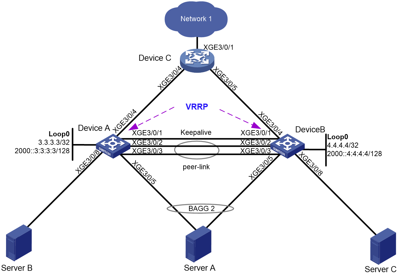
Network configuration
As shown in Figure 1:
· Device A and Device B form an M-LAG system. Server A is connected to the M-LAG system through M-LAG interfaces.
· Device A and Device B provide VRRP access for Server A.
· Device A and Device B are connected to uplink device Device A through ECMP routes.
· Server B and Server A are in the same network segment and connected to the network with a single uplink. Server C is in a different network segment from Server A and also connected to the network with a single uplink.
User requirements:
· Server A, Server B, and Server C have IPv4 and IPv6 dual-stack connectivity between them.
· Server A, Server B, and Server C have IPv4 and IPv6 dual-stack connectivity with the network.
· When a link between the two M-LAG member devices fails, the servers can still communicate.
|
Device |
Interface |
IP addresses |
Remarks |
|
Device A: |
LoopBack 0 |
3.3.3.3/32 2000::3:3:3:3/128 |
Loopback interface address. Router ID. |
|
XGE 3/0/8 |
N/A |
Server B Single-homed interface. |
|
|
XGE 3/0/5 |
N/A |
Server A M-LAG device interface. |
|
|
XGE 3/0/4 |
32.1.1.1/24 32::1/64 |
Device C: XGE 3/0/4 |
|
|
XGE 3/0/1 |
21.1.1.1/24 |
Device B: XGE 3/0/1 Keepalive link |
|
|
XGE 3/0/2 |
N/A |
Device B: XGE 3/0/2 The interface is used as the peer link interface. |
|
|
XGE 3/0/3 |
N/A |
Device B: XGE 3/0/3 The interface is used as the peer link interface. |
|
|
Vlan 100 |
100.1.1.1/24 100::1/64 |
VRRP gateway. |
|
|
Vlan 101 |
101.1.1.1/24 101::1/64 |
Interface of the Layer 3 link connecting the two M-LAG member devices, which is used for forwarding east-west traffic or allowing north-south traffic to escape. |
|
|
Device B: |
LoopBack 0 |
4.4.4.4/32 2000::4:4:4:4/128 |
Loopback interface address. Router ID. |
|
XGE 3/0/8 |
200.1.1.1/24 200::1/64 |
Server C Single-homed interface. |
|
|
XGE 3/0/5 |
N/A |
Server A M-LAG device interface. |
|
|
XGE 3/0/4 |
33.1.1.1/24 33::1/64 |
Device C: XGE 3/0/5 |
|
|
XGE 3/0/1 |
21.1.1.2/24 |
Device A: XGE 3/0/1 Keepalive link |
|
|
XGE 3/0/2 |
N/A |
Device A: XGE 3/0/2 The interface is used as the peer link interface. |
|
|
XGE 3/0/3 |
N/A |
Device A: XGE 3/0/3 The interface is used as the peer link interface. |
|
|
Vlan 100 |
100.1.1.2/24 100::2/64 |
VRRP gateway. |
|
|
Vlan 101 |
101.1.1.2/24 101::2/64 |
Interface of the Layer 3 link connecting the two M-LAG member devices, which is used for forwarding east-west traffic or allowing north-south traffic to escape. |
|
|
Device C: |
XGE 3/0/1 |
22.1.1.1/24 22::1/64 |
Network 1 |
|
XGE 3/0/4 |
32.1.1.2/24 32::2/64 |
Device A: XGE 3/0/4 |
|
|
XGE 3/0/5 |
33.1.1.2/24 33::2/64 |
Device B: XGE 3/0/4 |
|
|
Server A |
N/A |
100.1.1.11/24 100::11/64 |
Device A: XGE 3/0/5 Device B: XGE 3/0/5 |
|
Server B |
N/A |
100.1.1.12/24 100::12/64 |
Device A: XGE 3/0/8 |
|
Server C |
N/A |
200.1.1.11/24 200::11/64 |
Device B: XGE 3/0/8 |
|
Network 1 |
N/A |
22.1.1.11/24 22::11/64 |
Device C: XGE 3/0/1 |
Applicable product matrix
|
|
IMPORTANT: In addition to running an applicable software version, you must also install the most recent patch, if any. |
|
Device |
Software version |
|
S10500, S10500X, S7600, S7600-X, S7600E-X, S7500X, S7500E |
R7625 and later |
|
S12500G-AF (type T cards) |
R7625 and later |
|
S12500G-AF (type S cards) |
R8054P04 and later |
|
S10500X-G, S7500X-G |
R7754P04 and later |
|
S5590XP-HI-G, S6520X-EI-G, S6520XP-EI-G |
R7754P04 and later |
|
S6550XE-HI, S6525XE-HI |
R8106P22 and later |
|
S6520X-EI, S6520X-HI |
F6628P11 and later |
|
S5590-HI, S5590-EI, S6805-G, S6850-G, S6530X, S9850-G |
R8307P08 and later |
|
S5560X-HI |
F6628P11 and later |
|
S5560X-EI |
F6628P11 and later |
Analysis
· Configure M-LAG and VRRP on Device A and Device B.
· Connect Server A to the network with dual uplinks and configure the VRRP virtual IP address for VLAN 100 as the gateway address on the server.
· Connect Server B to the network with a single uplink and configure the VRRP virtual IP address for VLAN 100 as the gateway address on the server.
· Connect Server C to the network with a single uplink and configure the IP address for VLAN 200 as the gateway address on the server.
· Connect Device A and Device B to the upstream device (Device C) through ECMP routes.
· Configure OSPF/OSPFv3 neighbors between Device A and Device B, which provides connectivity for single-homed services and also serves as a backup path between the network side and single-homed services.
· Make sure both IPv4 and IPv6 network configurations exist.
Restrictions and guidelines
All devices in this example were started with the factory default configuration. When you are working on a live network, make sure you understand the potential impact of every command on your network.
Configuring M-LAG devices
Procedure summary
· Configuring the interconnect links between the M-LAG system and the downlink device Server A
· Configuring the Layer 3 link connecting the M-LAG member devices
· Configuring the links between the M-LAG member devices and uplink device Device C
· Configuring single-homed interface of the M-LAG member devices
Configuring M-LAG
|
Device A |
Device B |
Description |
Remarks |
|
m-lag system-mac 2-2-2 |
m-lag system-mac 2-2-2 |
Configure the M-LAG system MAC address. |
You must configure the same M-LAG system MAC address for devices in the same M-LAG system. |
|
m-lag system-number 1 |
m-lag system-number 2 |
Configure M-LAG system number. |
You must set different M-LAG system numbers for devices in the same M-LAG system. |
|
m-lag system-priority 123 |
m-lag system-priority 123 |
Configure the M-LAG system priority. |
You must set the same M-LAG system priority for devices in the same M-LAG system. |
|
m-lag standalone enable |
m-lag standalone enable |
(Optional.) Enable M-LAG standalone mode. |
When an M-LAG system splits, to prevent both devices in the M-LAG system from forwarding traffic as the primary device, you can configure this feature before the M-LAG system split. After configuring this feature, if the M-LAG system splits and both the peer link and keepalive link are in the DOWN state, the secondary device will immediately switch to standalone operation mode. |
|
m-lag keepalive ip destination 21.1.1.2 source 21.1.1.1 |
m-lag keepalive ip destination 21.1.1.1 source 21.1.1.2 |
Configure the destination and source IP addresses of keepalive packets. |
|
|
interface Ten-gigabitethernetE3/0/1 |
interface Ten-gigabitethernetE3/0/1 |
Enter the interface view for the keepalive link. |
|
|
port link-mode route |
port link-mode route |
Configure the interface for the keepalive link to operate in route mode as a Layer 3 interface. |
|
|
ip address 21.1.1.1 24 |
ip address 21.1.1.2 24 |
Configure the source IP address of keepalive packets. |
|
|
quit |
quit |
Return to system view. |
|
|
m-lag mad exclude interface Ten-gigabitethernetE3/0/1 |
m-lag mad exclude interface Ten-gigabitethernetE3/0/1 |
Exclude the interface for the keepalive link from the shutdown action by M-LAG MAD. |
|
|
interface bridge-aggregation 1 |
interface bridge-aggregation 1 |
Create the Layer 2 aggregate interface to be used as the peer-link interface and enter interface view. |
|
|
link-aggregation mode dynamic |
link-aggregation mode dynamic |
Configure the aggregate interface to operate in dynamic mode. |
|
|
quit |
quit |
Return to system view. |
|
|
interface range Ten-gigabitethernetE 3/0/2 Ten-gigabitethernetE 3/0/3 |
interface range Ten-gigabitethernetE 3/0/2 Ten-gigabitethernetE 3/0/3 |
Enter the view of physical interfaces on the peer link. |
|
|
port link-aggregation group 1 |
port link-aggregation group 1 |
Assign the physical interface for the peer link to the peer link aggregation group. |
|
|
quit |
quit |
Return to system view. |
|
|
interface bridge-aggregation 1 |
interface bridge-aggregation 1 |
Enter Ethernet aggregate interface view. |
|
|
port m-lag peer-link 1 |
port m-lag peer-link 1 |
Specify the aggregate interface (Bridge-Aggregation 1) as the peer-link interface. |
|
|
undo mac-address static source-check enable |
undo mac-address static source-check enable |
Disable the static source check feature to avoid inter-peer link Layer 3 traffic forwarding failures. |
N/A |
|
quit |
quit |
Return to system view. |
|
Configuring the interconnect links between the M-LAG system and the downlink device Server A
|
Device A |
Device B |
Description |
Remarks |
|
interface bridge-aggregation 2 |
interface bridge-aggregation 2 |
Create the Ethernet aggregate interface connecting to Server A. |
|
|
link-aggregation mode dynamic |
link-aggregation mode dynamic |
Configure the aggregate interface to operate in dynamic mode. |
|
|
port m-lag group 1 |
port m-lag group 1 |
Assign the aggregate interface to M-LAG group 1. |
|
|
port lacp system-priority 100 |
port lacp system-priority 101 |
Set the LACP system priority. |
With this configuration, only member ports with higher priority are selected when both peer link and keepalive link fail |
|
quit |
quit |
Return to system view. |
|
|
interface Ten-gigabitethernet 3/0/5 |
Interface Ten-gigabitethernet 3/0/5 |
Enter the view of the physical interface connecting the M-LAG system to Server A. |
|
|
port link-aggregation group 2 |
port link-aggregation group 2 |
Add the interface to the aggregation group. |
|
|
quit |
quit |
Return to system view. |
|
Configuring the Layer 3 link connecting the M-LAG member devices
|
Device A |
Device B |
Description |
Remarks |
|
router id 3.3.3.3 |
router id 4.4.4.4 |
Configure a router ID. |
|
|
ospf 1 |
ospf 1 |
Enable OSPF. |
|
|
import-route direct |
import-route direct |
Redistribute direct routes. |
|
|
area 0 |
area 0 |
Configure area 0. |
|
|
quit |
quit |
Return to OSPF view. |
|
|
quit |
quit |
Return to system view. |
|
|
ospfv3 1 |
ospfv3 1 |
Enable OSPFv3. |
|
|
router-id 3.3.3.3 |
router-id 4.4.4.4 |
Configure a router ID |
|
|
import-route direct |
import-route direct |
Redistribute direct routes. |
|
|
area 0 |
area 0 |
Configure area 0. |
|
|
quit |
quit |
Return to OSPFv3 view. |
|
|
quit |
quit |
Return to system view. |
|
|
interface Loopback 0 |
interface Loopback 0 |
Configure a loopback interface. |
|
|
ip address 3.3.3.3 255.255.255.255 |
ip address 4.4.4.4 255.255.255.255 |
Assign an IPv4 address to the loopback interface. |
|
|
ospf 1 area 0.0.0.0 |
ospf 1 area 0.0.0.0 |
Enable OSPF for the loopback interface. |
|
|
ipv6 address 2000::3:3:3:3/128 |
ipv6 address 2000::4:4:4:4/128 |
Assign an IPv6 address to the loopback interface. |
|
|
ospfv3 1 area 0.0.0.0 |
ospfv3 1 area 0.0.0.0 |
Enable OSPFv3 for the loopback interface. |
|
|
quit |
quit |
Return to system view. |
|
|
vlan 101 |
vlan 101 |
Create VLAN 101. |
|
|
quit |
quit |
Return to system view. |
|
|
interface vlan-interface 101 |
interface vlan-interface 101 |
Create VLAN-interface 101. |
|
|
ip address 101.1.1.1 255.255.255.0 |
ip address 101.1.1.2 255.255.255.0 |
Assign an IPv4 address to VLAN-interface 101. |
Interface of the Layer 3 link connecting the two M-LAG member devices, which is used for forwarding east-west traffic or allowing north-south traffic to escape. |
|
ospf 1 area 0.0.0.0 |
ospf 1 area 0.0.0.0 |
Enable OSPF for the interface. |
|
|
ipv6 address 101::1 64 |
ipv6 address 101::2 64 |
Assign an IPv6 address to VLAN-interface 101. |
Interface of the Layer 3 link connecting the two M-LAG member devices, which is used for forwarding east-west traffic or allowing north-south traffic to escape. |
|
ospfv3 1 area 0.0.0.0 |
ospfv3 1 area 0.0.0.0 |
Enable OSPFv3 for the interface. |
|
|
quit |
quit |
Return to system view. |
|
|
m-lag mad exclude interface Vlan-interface 101 |
m-lag mad exclude interface Vlan-interface 101 |
Exclude VLAN-interface 101 from the shutdown action by M-LAG MAD. |
|
Configuring VRRP gateways
|
Device A |
Device B |
Description |
Remarks |
|
vlan 100 |
vlan 100 |
Create VLAN 100. |
|
|
interface bridge-aggregation 2 |
interface bridge-aggregation 2 |
Create Layer 2 aggregate interface Bridge-Aggregation 2, and enter its view. |
|
|
port link-type trunk |
port link-type trunk |
Set the link type of the Layer 2 aggregate interface to trunk. |
|
|
port trunk permit vlan 100 |
port trunk permit vlan 100 |
Assign the interface to VLAN 100. |
|
|
undo port trunk permit vlan 1 |
undo port trunk permit vlan 1 |
Remove the interface from VLAN 1. |
|
|
quit |
quit |
Return to system view. |
|
|
interface vlan-interface 100 |
interface vlan-interface 100 |
Create VLAN-interface 100. |
|
|
ip address 100.1.1.1 24 |
ip address 100.1.1.2 24 |
Assign an IPv4 address to VLAN-interface 100. |
|
|
vrrp vrid 1 virtual-ip 100.1.1.100 |
vrrp vrid 1 virtual-ip 100.1.1.100 |
Create IPv4 VRRP group 1, and configure virtual IP address 100.1.1.100 for the VRRP group. |
|
|
vrrp vrid 1 priority 200 |
N/A |
Configure the priority of the device in VRRP group 1. |
This configuration ensures that Device A can become the master. |
|
ipv6 address 100::1 64 |
ipv6 address 100::2 64 |
Assign an IPv6 address to VLAN-interface 100. |
|
|
ipv6 address fe80:100::1 link-local |
ipv6 address fe80:100::2 link-local |
Assign an IPv6 link-local address to VLAN-interface 100. |
|
|
vrrp ipv6 vrid 1 virtual-ip fe80:100::100 link-local |
vrrp ipv6 vrid 1 virtual-ip fe80:100::100 link-local |
Create IPv6 VRRP group 1, and configure virtual IPv6 address fe80:100::100 for IPv6 VRRP group 1. |
|
|
vrrp ipv6 vrid 1 virtual-ip 100::100 |
vrrp ipv6 vrid 1 virtual-ip 100::100 |
Create IPv6 VRRP group 1, and configure virtual IPv6 address 100::100 for IPv6 VRRP group 1. |
|
|
vrrp ipv6 vrid 1 priority 200 |
N/A |
Configure the priority of the device in IPv6 VRRP group 1 to 200. |
This configuration ensures that Device A can become the master. |
|
quit |
quit |
Return to system view. |
|
|
m-lag mad exclude interface Vlan-interface100 |
m-lag mad exclude interface Vlan-interface100 |
Configure M-LAG MAD to not shut down VLAN-interface 100. |
This configuration avoids traffic interruption caused by ARP/ND entry synchronization failure when the VLAN interface is in M-LAG MAD DOWN state. |
Configuring the links between the M-LAG member devices and uplink device Device C
|
Device A |
Device B |
Description |
Remarks |
|
vlan 32 |
vlan 33 |
Create a VLAN. |
|
|
quit |
quit |
Return to system view. |
|
|
interface Ten-gigabitethernet 3/0/4 |
interface Ten-gigabitethernet 3/0/4 |
Enter interface view. |
|
|
port access vlan 32 |
port access vlan 33 |
Assign the access port to the specified VLAN. |
|
|
quit |
quit |
Return to system view. |
|
|
interface vlan-interface 32 |
interface vlan-interface 33 |
Create a VLAN interface. |
|
|
ip address 32.1.1.1 24 |
ip address 33.1.1.1 24 |
Configure an IP address for the VLAN interface. |
|
|
ospf 1 area 0 |
ospf 1 area 0 |
Enable OSPF on the interface. |
|
|
ipv6 address 32::1 64 |
ipv6 address 33::1 64 |
Configure an IP address for the VLAN interface. |
|
|
ospfv3 1 area 0 |
ospfv3 1 area 0 |
Enable OSPFv3 on the interface. |
|
|
quit |
quit |
Return to system view. |
|
Configuring single-homed interface of the M-LAG member devices
|
Device A |
Device B |
Description |
Remarks |
|
N/A |
vlan 200 |
Create a VLAN. |
|
|
N/A |
quit |
Return to system view. |
|
|
interface ten-gigabitethernet 3/0/8 |
interface ten-gigabitethernet 3/0/8 |
Configure the single-homed interface of Server B and Server C. |
|
|
port access vlan 100 |
port access vlan 200 |
Assign the access port to the specified VLAN. |
|
|
quit |
quit |
Return to system view. |
|
|
N/A |
interface vlan-interface 200 |
Create a VLAN interface. |
|
|
N/A |
ip address 200.1.1.1 24 |
Configure an IP address for the VLAN interface. |
|
|
N/A |
ipv6 address 200::1 64 |
Configure an IPv6 address for the VLAN interface. |
|
|
N/A |
quit |
Return to system view. |
|
Configuring uplink device Device C
Procedure summary
· Configuring the links between uplink device Device C and M-LAG member devices
· Configuring the links between uplink device Device C and the network
Configuring the links between uplink device Device C and M-LAG member devices
|
Device C |
Description |
Remarks |
|
undo stp global enable |
Disable STP globally. |
|
|
vlan 32 33 |
Create a VLAN. |
|
|
interface Ten-gigabitethernetE 3/0/4 |
Enter interface view. |
|
|
port access vlan 32 |
Assign the interface on Device C connected to Device A to VLAN 32. |
|
|
quit |
Return to system view. |
|
|
interface Ten-gigabitethernetE 3/0/5 |
Enter interface view. |
|
|
port access vlan 33 |
Assign the interface on Device C connected to Device B to VLAN 33. |
|
|
quit |
Return to system view. |
|
|
router id 5.5.5.5 |
Configure a router ID. |
|
|
ospf 1 |
Configure OSPF to implement IPv4 network connectivity between M-LAG member devices. |
|
|
import-route direct |
Redistribute direct routes. |
|
|
area 0 |
Configure area 0. |
|
|
quit |
Return to OSPF view. |
|
|
quit |
Return to system view. |
|
|
ospfv3 1 |
Enable OSPFv3. |
|
|
router-id 5.5.5.5 |
Configure a router ID. |
|
|
import-route direct |
Redistribute direct routes. |
|
|
area 0 |
Configure area 0. |
|
|
quit |
Return to OSPFv3 view. |
|
|
quit |
Return to system view. |
|
|
interface loopback 0 |
Create a loopback interface. |
|
|
ip address 5.5.5.5 255.255.255.255 |
Configure an IPv4 address for the loopback interface. |
|
|
ospf 1 area 0 |
Enable OSPF for the loopback interface. |
|
|
ipv6 address 2000::5:5:5:5/128 |
Configure an IPv6 address for the loopback interface. |
|
|
ospfv3 1 area 0 |
Enable OSPFv3 for the loopback interface. |
|
|
quit |
N/A |
|
|
interface vlan-interface 32 |
Create VLAN-interface 32. |
|
|
ip address 32.1.1.2 24 |
Configure an IPv4 address for the VLAN interface. |
|
|
ospf 1 area 0 |
Enable OSPF for the VLAN interface. |
|
|
ipv6 address 32::2 64 |
Configure an IPv6 address for the VLAN interface. |
|
|
ospfv3 1 area 0 |
Enable OSPFv3 for the VLAN interface. |
|
|
quit |
Return to system view. |
|
|
interface vlan-interface 33 |
Create VLAN-interface 33. |
|
|
ip address 33.1.1.2 24 |
Configure an IPv4 address for the VLAN interface. |
|
|
ospf 1 area 0 |
Enable OSPF for the VLAN interface. |
|
|
ipv6 address 33::2 64 |
Configure an IPv6 address for the VLAN interface. |
|
|
ospfv3 1 area 0 |
Enable OSPFv3 for the VLAN interface. |
|
|
quit |
Return to system view. |
|
Configuring the links between uplink device Device C and the network
|
Device C |
Description |
Remarks |
|
vlan 22 |
Create VLAN 22. |
|
|
quit |
Return to system view. |
|
|
interface Ten-gigabitethernet 3/0/1 |
Enter interface view |
|
|
port access vlan 22 |
Assign the interface on Device C connected to the external network to VLAN 22. |
|
|
quit |
Return to system view. |
|
|
interface vlan-interface 22 |
Create VLAN-interface 22. |
|
|
ip address 22.1.1.1 24 |
Configure an IPv4 address for the VLAN interface. |
|
|
ipv6 address 22::1 64 |
Configure an IPv6 address for the VLAN interface. |
|
|
quit |
Return to system view. |
|
Traffic model
About the traffic model
The traffic model contains the following information:
· ID—Traffic ID, in O-X-XXX format. The first segment (O) represents overlay traffic. The second segment (X) represents the IP version (4 for IPv4 and 6 for IPv6). The third segment (XXX) represents a unique number for the traffic.
· Type—Traffic type, such as known unicast/IPv4 and unicast/L2.
· Direction—Traffic direction, such as inter-leaf east-west traffic and north-south traffic.
· Path—The nodes that the traffic traverses from the source to the destination.
· Simulation method—Traffic simulation method. Testers are used to simulate the patterns of traffic on the network set up in this example.
· Simulation traffic load—The network can be tested under light load (fewer than 1000 simulation traffic flows) or heavy load (more than 1000 simulation traffic flows).
· Traffic direction to firewalls/LBs—No firewalls or LBs are used in this example, or traffic is directed to firewalls or LBs through PBR, M-LAG+VRRP, or static routing.
Traffic
|
ID |
Type |
Direction |
Path |
Simulation method |
Simulation traffic load |
Traffic direction to firewalls/LBs |
Remarks |
|
O-4-001 |
Known unicast/IPv4 |
North-south traffic |
ServerA-DeviceA&B-DeviceC-Network1 |
Tester |
Light |
N/A |
When the uplink interface fails, traffic is forwarded along the Layer 3 link between M-LAG member devices. |
|
O-4-002 |
Known unicast/IPv4 |
North-south traffic |
ServerB-DeviceA-DeviceC-Network1 |
Tester |
Light |
N/A |
|
|
O-4-003 |
Known unicast/IPv4 |
North-south traffic |
ServerC-DeviceB-DeviceC-Network1 |
Tester |
Light |
N/A |
|
|
O-4-004 |
Known unicast/IPv4 |
East-west traffic |
ServerA-DeviceA&B-DeviceA-ServerB |
Tester |
Light |
N/A |
|
|
O-4-005 |
Known unicast/IPv4 |
East-west traffic |
ServerA-DeviceA&B-DeviceB-ServerC |
Tester |
Light |
N/A |
|
|
O-4-006 |
Known unicast/IPv4 |
East-west traffic |
ServerB-DeviceA-DeviceB-ServerC |
Tester |
Light |
N/A |
|
|
O-6-001 |
Known unicast/IPv6 |
North-south traffic |
ServerA-DeviceA&B-DeviceC-Network1 |
Tester |
Light |
N/A |
When the uplink interface fails, traffic is forwarded along the Layer 3 link between M-LAG member devices. |
|
O-6-002 |
Known unicast/IPv6 |
North-south traffic |
ServerB-DeviceA-DeviceC-Network1 |
Tester |
Light |
N/A |
|
|
O-6-003 |
Known unicast/IPv6 |
North-south traffic |
ServerC-DeviceB-DeviceC-Network1 |
Tester |
Light |
N/A |
|
|
O-6-004 |
Known unicast/IPv4 |
East-west traffic |
ServerA-DeviceA&B-DeviceA-ServerB |
Tester |
Light |
N/A |
|
|
O-6-005 |
Known unicast/IPv4 |
East-west traffic |
ServerA-DeviceA&B-DeviceB-ServerC |
Tester |
Light |
N/A |
|
|
O-6-006 |
Known unicast/IPv4 |
East-west traffic |
ServerB-DeviceA-DeviceB-ServerC |
Tester |
Light |
N/A |
|
Convergence performance test results
Failure test results
Table 1 Link failure test results
|
Device |
Failure cause |
Traffic downtime |
Remarks |
|
Device A |
Single member link failure in an M-LAG interface |
≤ 400 ms |
|
|
Recovery from a single M-LAG interface member link failure |
≤ 100 ms |
|
|
|
Single uplink failure |
≤ 400 ms |
|
|
|
Recovery from a single uplink failure |
≤ 100 ms |
|
|
|
Complete peer link failure |
≤ 1000 ms |
Focus on M-LAG interface services. Single-homed interface services are not assured. |
|
|
Recovery from a complete peer link failure |
≤ 100 ms |
Focus on M-LAG interface services. Single-homed interface services are not assured. |
|
|
Keepalive link failure |
0 ms |
|
|
|
Recovery from a keepalive link failure |
0 ms |
|
|
|
Keepalive link and peer link failure |
≤ 4000 ms |
Focus on M-LAG interface services. Single-homed interface services are not assured. |
|
|
Recovery from a keepalive link and peer link failure |
≤ 4000 ms |
Focus on M-LAG interface services. Single-homed interface services are not assured. |
|
|
Restart of one M-LAG member device |
≤ 100 ms |
Focus on M-LAG interface services. Single-homed interface services are not assured. |
|
|
Recovery from M-LAG member device restart |
≤ 100 ms |
Focus on M-LAG interface services. Single-homed interface services are not assured. |
|
|
Switching fabric module failure |
≤ 100 ms |
|
|
|
Recovery from a switching fabric module failure |
≤ 100 ms |
|
Verifying the configuration
Verification commands
Table 2 Verification commands
|
Device A |
Device B |
Description |
|
display m-lag summary |
display m-lag summary |
Displays display summary information about the peer-link interface and M-LAG interfaces. |
|
display m-lag keepalive |
display m-lag keepalive |
Displays M-LAG keepalive packet statistics. |
|
display m-lag role |
display m-lag role |
Displays M-LAG role information. |
|
display m-lag verbose |
display m-lag verbose |
Displays detailed information about the peer-link interface and M-LAG interfaces. |
|
display vrrp verbose |
display vrrp verbose |
Displays detailed IPv4 VRRP group information. |
|
display vrrp ipv6 verbose |
display vrrp ipv6 verbose |
Displays detailed IPv6 VRRP group information. |
Procedure
Verifying the M-LAG system status
View the status of the M-LAG system between Device A and Device B to verify that the M-LAG system can be established correctly.
# Display summary information about the peer-link interface and M-LAG interfaces.
[DeviceA] display m-lag summary
Flags: A -- Aggregate interface down, B -- No peer M-LAG interface configured
C -- Configuration consistency check failed
peer-link interface : BAGG1
peer-link interface state (cause): UP
Keepalive link state (cause): UP
M-LAG interface information
M-LAG IF M-LAG group Local state (cause) Peer state Remaining down time(s)
BAGG2 1 UP UP -
[DeviceA]
[DeviceB] display m-lag summary
Flags: A -- Aggregate interface down, B -- No peer M-LAG interface configured
C -- Configuration consistency check failed
peer-link interface : BAGG1
peer-link interface state (cause): UP
Keepalive link state (cause): UP
M-LAG interface information
M-LAG IF M-LAG group Local state (cause) Peer state Remaining down time(s)
BAGG2 1 UP UP -
# Display M-LAG keepalive packet statistics to verify that the keepalive packet sending and receiving states are both successful.
[DeviceA] display m-lag keepalive
Neighbor keepalive link status (cause): Up
Neighbor is alive for: 144023 s 840 ms
Keepalive packet transmission status:
Sent: Successful
Received: Successful
Last received keepalive packet information:
Source IP address: 21.1.1.2
Time: 2020/05/11 10:21:12
Action: Accept
M-LAG keepalive parameters:
Destination IP address: 21.1.1.2
Source IP address: 21.1.1.1
Keepalive UDP port : 6400
Keepalive VPN name : N/A
Keepalive interval : 1000 ms
Keepalive timeout : 5 sec
Keepalive hold time: 3 sec
[DeviceA]
[DeviceB] display m-lag keepalive
Neighbor keepalive link status (cause): Up
Neighbor is alive for: 144177 s 921 ms
Keepalive packet transmission status:
Sent: Successful
Received: Successful
Last received keepalive packet information:
Source IP address: 21.1.1.1
Time: 2020/05/11 10:23:47
Action: Accept
M-LAG keepalive parameters:
Destination IP address: 21.1.1.1
Source IP address: 21.1.1.2
Keepalive UDP port : 6400
Keepalive VPN name : N/A
Keepalive interval : 1000 ms
Keepalive timeout : 5 sec
Keepalive hold time: 3 sec
# Display M-LAG role information.
[DeviceA] display m-lag role
Effective role information
Factors Local Peer
Effective role Primary Secondary
Initial role None None
MAD DOWN state Yes Yes
Health level 0 0
Role priority 32768 32768
Bridge MAC b0f9-63b6-4c00 b0f9-63b6-4c09
Effective role trigger: peer-link calculation
Effective role reason: Bridge MAC
Configured role information
Factors Local Peer
Configured role Primary Secondary
Role priority 32768 32768
Bridge MAC b0f9-63b6-4c00 b0f9-63b6-4c09
[DeviceA]
[DeviceB] display m-lag role
Effective role information
Factors Local Peer
Effective role Secondary Primary
Initial role None None
MAD DOWN state Yes Yes
Health level 0 0
Role priority 32768 32768
Bridge MAC b0f9-63b6-4c09 b0f9-63b6-4c00
Effective role trigger: peer-link calculation
Effective role reason: Bridge MAC
Configured role information
Factors Local Peer
Configured role Secondary Primary
Role priority 32768 32768
Bridge MAC b0f9-63b6-4c09 b0f9-63b6-4c00
# Display detailed information about the peer-link interface and M-LAG interfaces.
[DeviceA] display m-lag verbose
Flags: A -- Home_Gateway, B -- Neighbor_Gateway, C -- Other_Gateway,
D -- PeerLink_Activity, E -- DRCP_Timeout, F -- Gateway_Sync,
G -- Port_Sync, H -- Expired
peer-link interface/peer-link interface ID: BAGG1/1
State: UP
Cause: -
Local DRCP flags/Peer DRCP flags: ABDFG/ABDFG
Local Selected ports (index): TE3/0/2 (2), TE3/0/3 (3)
Peer Selected ports indexes: 99, 100
M-LAG interface/M-LAG group ID: BAGG2/1
Local M-LAG interface state: UP
Peer M-LAG interface state: UP
M-LAG group state: UP
Local M-LAG interface down cause: -
Remaining M-LAG DOWN time: -
Local M-LAG interface LACP MAC: Config=N/A, Effective=0002-0002-0002
Peer M-LAG interface LACP MAC: Config=N/A, Effective=0002-0002-0002
Local M-LAG interface LACP priority: Config=32768, Effective=123
Peer M-LAG interface LACP priority: Config=32768, Effective=123
Local DRCP flags/Peer DRCP flags: ABDFG/ABDFG
Local Selected ports (index): TE3/0/5 (5)
Peer Selected ports indexes: 102
[DeviceB] display m-lag verbose
Flags: A -- Home_Gateway, B -- Neighbor_Gateway, C -- Other_Gateway,
D –- PeerLink_Activity, E -- DRCP_Timeout, F -- Gateway_Sync,
G -- Port_Sync, H -- Expired
peer-link/peer-link ID: BAGG1/1
State: UP
Cause: -
Local DRCP flags/Peer DRCP flags: ABDFG/ABDFG
Local Selected ports (index): TE3/0/2 (99), TE3/0/3 (100)
Peer Selected ports indexes: 2, 3
M-LAG interface/M-LAG group ID: BAGG2/1
Local M-LAG interface state: UP
Peer M-LAG interface state: UP
M-LAG group state: UP
Local M-LAG interface down cause: -
Remaining M-LAG DOWN time: -
Local M-LAG interface LACP MAC: Config=N/A, Effective=0002-0002-0002
Peer M-LAG interface LACP MAC: Config=N/A, Effective=0002-0002-0002
Local M-LAG interface LACP priority: Config=32768, Effective=123
Peer M-LAG interface LACP priority: Config=32768, Effective=123
Local DRCP flags/Peer DRCP flags: ABDFG/ABDFG
Local Selected ports (index): TE3/0/5 (102)
Peer Selected ports indexes: 5
Verifying the routing protocol status
# Display OSPF neighbor information on Device A.
[DeviceA] display ospf peer
OSPF Process 1 with Router ID 3.3.3.3
Neighbor Brief Information
Area: 0.0.0.0
Router ID Address Pri Dead-Time State Interface
4.4.4.4 101.1.1.2 1 32 Full/BDR Vlan101
5.5.5.5 32.1.1.2 1 38 Full/DR Vlan32
# Display OSPFv3 neighbor information on Device A.
[DeviceA] display ospfv3 peer
OSPFv3 Process 1 with Router ID 3.3.3.3
Area: 0.0.0.0
-------------------------------------------------------------------------
Router ID Pri State Dead-Time InstID Interface
4.4.4.4 1 Full/BDR 00:00:39 0 Vlan101
5.5.5.5 1 Full/BDR 00:00:40 0 Vlan32
# Display OSPF neighbor information on Device B.
[DeviceB] display ospf peer
OSPF Process 1 with Router ID 4.4.4.4
Neighbor Brief Information
Area: 0.0.0.0
Router ID Address Pri Dead-Time State Interface
3.3.3.3 101.1.1.1 1 33 Full/DR Vlan101
5.5.5.5 33.1.1.2 1 31 Full/DR Vlan33
# Display OSPFv3 neighbor information on Device B.
[DeviceB] display ospfv3 peer
OSPFv3 Process 1 with Router ID 4.4.4.4
Area: 0.0.0.0
-------------------------------------------------------------------------
Router ID Pri State Dead-Time InstID Interface
3.3.3.3 1 Full/DR 00:00:36 0 Vlan101
5.5.5.5 1 Full/BDR 00:00:39 0 Vlan33
# Display OSPF neighbor information on Device C.
[DeviceC] display ospf peer
OSPF Process 1 with Router ID 5.5.5.5
Neighbor Brief Information
Area: 0.0.0.0
Router ID Address Pri Dead-Time State Interface
3.3.3.3 32.1.1.1 1 35 Full/BDR Vlan32
4.4.4.4 33.1.1.1 1 35 Full/BDR Vlan33
# Display OSPFv3 neighbor information on Device C.
[DeviceC] display ospfv3 peer
OSPFv3 Process 1 with Router ID 5.5.5.5
Area: 0.0.0.0
-------------------------------------------------------------------------
Router ID Pri State Dead-Time InstID Interface
3.3.3.3 1 Full/DR 00:00:38 0 Vlan32
4.4.4.4 1 Full/DR 00:00:35 0 Vlan33
Verifying the VRRP group status
# Display detailed information about IPv4 VRRP group 1 on Device A.
[DeviceA] display vrrp verbose
IPv4 Virtual Router Information:
Running mode : Standard
Total number of virtual routers : 1
Interface Vlan-interface100
VRID : 1 Adver Timer : 100
Admin Status : Up State : Master
Config Pri : 200 Running Pri : 200
Preempt Mode : Yes Delay Time : 0
Auth Type : Not supported
Version : 3
Virtual IP : 100.1.1.100
Virtual MAC : 0000-5e00-0101
Master IP : 100.1.1.1
# Display detailed information about IPv6 VRRP group 1 on Device A.
[DeviceA] display vrrp ipv6 verbose
IPv6 Virtual Router Information:
Running mode : Standard
Total number of virtual routers : 1
Interface Vlan-interface100
VRID : 1 Adver Timer : 100
Admin Status : Up State : Master
Config Pri : 200 Running Pri : 200
Preempt Mode : Yes Delay Time : 0
Auth Type : None
Virtual IP : FE80:10:100
100::100
Virtual MAC : 0000-5e00-0201
Master IP : FE80::B2F9:63FF:FEB6:4C01
# Display detailed information about IPv4 VRRP group 1 on Device B.
[DeviceB] display vrrp verbose
IPv4 Virtual Router Information:
Running mode : Standard
Total number of virtual routers : 1
Interface Vlan-interface100
VRID : 1 Adver Timer : 100
Admin Status : Up State : Backup
Config Pri : 100 Running Pri : 100
Preempt Mode : Yes Delay Time : 0
Become Master : 3530ms left
Auth Type : Not supported
Version : 3
Virtual IP : 100.1.1.100
Virtual MAC : 0000-5e00-0101
Master IP : 100.1.1.1
# Display detailed information about IPv6 VRRP group 1 on Device B.
[DeviceB] display vrrp ipv6 verbose
IPv6 Virtual Router Information:
Running mode : Standard
Total number of virtual routers : 1
Interface Vlan-interface100
VRID : 1 Adver Timer : 100
Admin Status : Up State : Backup
Config Pri : 100 Running Pri : 100
Preempt Mode : Yes Delay Time : 0
Become Master : 3380ms left
Auth Type : None
Virtual IP : FE80:10:100
100::100
Virtual MAC : 0000-5e00-0201
Master IP : FE80::B2F9:63FF:FEB6:4C01
Verifying interconnectivity between Server A, Server B, Server C, and Network 1
Verify that Server A and Server B can communicate with each other on the same IPv4 or IPv6 network.
Verify that Server A, Server B, and Server C can communicate with each other across IPv4 or IPv6 networks.
Verify that Server A, Server B, Server C, and Network 1 can communicate with each other across IPv4 or IPv6 networks.
Verifying interconnectivity between Server A, Server B, Server C, and Network upon downlink interface failure on Device A or Device B
Shut down the interface on Device A connected to Server A, and verify that Server A can still communicate with Server B, Server C, and Network (temporary packet loss occurs during traffic switchover).
Shut down the interface on Device B connected to Server A, and verify that Server A can still communicate with Server B, Server C, and Network (temporary packet loss occurs during traffic switchover).
Verifying interconnectivity between Server A, Server B, Server C, and Network upon uplink interface failure on Device A or Device B
Shut down the interface on Device A connected to Device C, and verify that Server A, Server B, and Server C can still communicate with Network (temporary packet loss occurs during traffic switchover).
Shut down the interface on Device B connected to Device C, and verify that Server A, Server B, and Server C can still communicate with Network (temporary packet loss occurs during traffic switchover).
Upgrade procedure
Pre-upgrade verification commands
Before you perform an upgrade, use the commands in "Verifying the configuration" and the commands in the following table to verify that all requirements are met for an upgrade.
Table 3 Pre-upgrade verification commands
|
Device A |
Device B |
Description |
|
display device |
display device |
Displays summary information about the peer link interfaces and M-LAG interfaces in the M-LAG system. |
|
display boot-loader |
display boot-loader |
Displays the current software images and startup software images. |
|
display version |
display version |
Displays system version information. |
Upgrade procedure
To upgrade software:
1. Execute the display version command to verify the current BootWare image version and startup software version.
2. Use the release notes for the upgrade software version to evaluate the upgrade impact on your network and verify the following items:
¡ Software and hardware compatibility.
¡ Version and size of the upgrade software.
¡ Compatibility of the upgrade software with the current BootWare image and startup software image.
3. Use the release notes to verify whether the upgrade software images require a license. If licenses are required, check the system for availability of valid licenses. If no valid licenses are available, install licenses first. If no licenses are installed, the upgrade software image installation will fail.
4. Use the dir command to verify that the device has sufficient storage space for the upgrade images. If the storage space is not sufficient, delete unused files by using the delete command. Make sure all MPUs in the system have sufficient storage space.
5. After Device A and Device B form an M-LAG system, perform the following tasks:
a. Check the LLDP neighbors of Device A to obtain the LLDP state information of all interfaces on Device A.
b. Manually shut down all interfaces connecting to the other devices (except M-LAG peer link interfaces and keepalive interfaces) on Device A.
c. Switch all incoming and outgoing traffic of Device A to Device B.
6. Save the configuration on Device A, and use FTP or TFTP to transfer the upgrade image file to the root directory of a file system. Upgrade Device A and reboot it.
7. When Device A is being rebooted, manually shut down the interfaces connecting Device B to Device A. The interfaces are typically peer link interfaces and keepalive interfaces.
8. After Device A is rebooted, bring up the interfaces that have been shut down on Device B. Wait for M-LAG to restore between Device A and Device B.
9. After Device A and Device B form an M-LAG system again, bring up the interfaces connecting to other devices. Wait for the traffic to restore.
For more information about upgrading software on an M-LAG system, see H3C Switches M-LAG System Upgrade Guide.
For more information about the software upgrade procedure, see the fundamentals configuration guide for the device.
Estimated upgrade downtime
See "Convergence performance test results." The upgrade downtime of each device contains the traffic downtime for restart of one M-LAG member device and recovery from M-LAG member device restart.
Post-upgrade verification commands
After the upgrade finishes, use the commands in "Verifying the configuration" and the commands in the following table to verify that the upgrade has been done correctly.
Table 4 Post-upgrade verification commands
|
Device A |
Device B |
Description |
|
display device |
display device |
Displays summary information about the peer link interfaces and M-LAG interfaces in the M-LAG system. |
|
display boot-loader |
display boot-loader |
Displays the current software images and startup software images. |
|
display version |
display version |
Displays system version information. |
Node expansion
Pre-expansion verification commands
Before you perform a node expansion, use the commands in "Verifying the configuration" and the commands in the following table to verify that all requirements are met for an expansion.
Table 5 Pre-expansion verification commands
|
Device A |
Device B |
Description |
|
display device |
display device |
Displays summary information about the peer link interfaces and M-LAG interfaces in the M-LAG system. |
|
display boot-loader |
display boot-loader |
Displays the current software images and startup software images. |
|
display version |
display version |
Displays system version information. |
Node expansion
1. Make sure the expansion device is not connected to the management network.
2. Upgrade the device to the target software version.
3. Configure the device.
4. Connect the device to the management network.
Estimating expansion downtime
N/A
Post-expansion verification commands
After the expansion finishes, use the commands in the following table to verify that the expansion has been done correctly.
Table 6 Post-expansion verification commands
|
Device A |
Device B |
Description |
|
display device |
display device |
Displays summary information about the peer link interfaces and M-LAG interfaces in the M-LAG system. |
|
display boot-loader |
display boot-loader |
Displays the current software images and startup software images. |
|
display version |
display version |
Displays system version information. |
Replacement procedure
Service module replacement
Pre-replacement verification commands
Execute the commands in "Verifying the configuration" and the following commands to verify that all requirements are met for a replacement.
Table 7 Pre-replacement verification commands
|
Device A |
Device B |
Description |
|
display device |
display device |
Displays device information. |
|
display boot-loader |
display boot-loader |
Displays the current software images and startup software images. |
|
display version |
display version |
Displays system version information. |
Replacement procedure
Before you replace an interface module, make sure the service and management traffic has switched over to other interface modules that are operating correctly.
Replace the interface modules online while the system is operating or power off the system before you do the replacement, depending on the evaluation of the conditions.
Estimated replacement downtime
See "Convergence performance test results." The replacement downtime of each interface module contains the traffic downtime for single member link failure in an M-LAG interface, single uplink failure, recovery from a single member link failure in an M-LAG interface, and recovery from a single uplink failure.
Post-replacement verification commands
Use the same commands for pre-replacement verification to verify that the system can operate correctly after the hardware replacement.
Switching fabric module replacement
Pre-replacement verification commands
Execute the commands in "Verifying the configuration" and the following commands to verify that all requirements are met for a replacement.
Table 8 Pre-replacement verification commands
|
Device A |
Device B |
Description |
|
display device |
display device |
Displays summary information about the peer link interfaces and M-LAG interfaces in the M-LAG system. |
|
display boot-loader |
display boot-loader |
Displays the current software images and startup software images. |
|
display version |
display version |
Displays system version information. |
Replacement procedure
Replace the switching fabric module online while the system is operating or power off the system before you do the replacement, depending on the evaluation of the conditions.
Estimated replacement downtime
See "Convergence performance test results." The replacement downtime of each switching fabric module contains the traffic downtime for switching fabric module failure and recovery from a switching fabric module failure.
Post-replacement verification commands
Use the same commands for pre-replacement verification to verify that the system can operate correctly after the hardware replacement.
