- Table of Contents
-
- H3C Campus Switches M-LAG Configuration Guide-6W101
- 00-M-LAG network planning for campus networks
- 01-M-LAG and VRRP Configuration Example (Campus)
- 02-M-LAG + Spanning Tree Configuration Example (Campus)
- 03-Dual-Active VLAN Gateway Configuration Example (Campus)
- 04-M-LAG and Loop Detection Configuration Example (Campus)
- 05-Multi-Tier M-LAG and VRRP Configuration Example (Campus)
- 06-M-LAG + VXLAN Distributed Gateway Network Configuration Example (Ethernet Aggregate Link as Peer Link) (Campus)
- 07-M-LAG + EVPN VXLAN Centralized Gateway Network Configuration Example (Ethernet Aggregate Link as Peer Link) (Campus)
- 08-M-LAG and MPLS L3VPN Configuraion Example (Campus)
- 09-M-LAG and Mirroring Configuration Example (Campus)
- Related Documents
-
| Title | Size | Download |
|---|---|---|
| 00-M-LAG network planning for campus networks | 362.24 KB |
M-LAG network planning for campus networks
Comparison between IRF and M-LAG
M-LAG network planning schemes
M-LAG in large campus networks
M-LAG in medium campus networks
M-LAG in small campus networks
Restrictions and guidelines for M-LAG system setup
M-LAG network planning for campus networks
Comparison between IRF and M-LAG
Multichassis Link Aggregation (M-LAG) virtualizes two physical devices into one system through multi-chassis link aggregation for device redundancy and traffic load sharing.
Table 1 shows the differences between IRF and M-LAG. For high availability and short service interruption during software upgrade, use M-LAG. You cannot use IRF and M-LAG in conjunction on the same device.
Table 1 Comparison between IRF and M-LAG
|
Item |
IRF |
M-LAG |
|
Control plane |
· The IRF member devices have a unified control plane for central management. · The IRF member devices synchronize all forwarding entries. |
· The control plane of the M-LAG member devices is separate. · The M-LAG member devices synchronize entries such as MAC, ARP, and ND entries. |
|
Device requirements |
· Hardware: The chips of the IRF member devices must have the same architecture, and the IRF member devices are from the same series. · Software: The IRF member devices must run the same software version. |
· Hardware: The M-LAG member devices can be different models. · Software: Some device models can run different software versions when they act as M-LAG member devices. Full support for different software versions will be implemented in the future. |
|
Software upgrade |
· The IRF member devices are upgraded simultaneously or separately. A separate upgrade is complex. · Services are interrupted for more than 30 seconds during a traditional master/subordinate switchover upgrade (without using ISSU), and services are interrupted for about 2 seconds during an ISSU upgrade. |
The M-LAG member devices are upgrade separately, and the service interruption time is shorter than 1 second during an upgrade. If the software supports graceful insertion and removal (GIR), an upgrade does not interrupt services. For more information about upgrading the M-LAG member devices by using GIR, see H3C Switches M-LAG System Upgrade Guide. |
|
Management |
The IRF member devices are configured and managed in a unified manner. Single points of failure might occur when a controller manages the IRF member devices. |
The M-LAG member devices are configured separately, and they can perform configuration consistency check for you to remove inconsistencies in the configuration that affects operation of the M-LAG system. You must ensure that service features also have consistent configuration. The M-LAG member devices are managed separately. No single point of failure will occur when a controller manages the M-LAG member devices. |
|
|
NOTE: GIR enables you to gracefully isolate a device from the network for device maintenance or upgrade. GIR minimizes service interruption by instructing the affected protocols (for example, routing protocols) to isolate the device and switch over to the redundant path. You do not need to configure graceful switchover protocol by protocol. For more information about GIR, see Fundamentals Configuration Guide for the devices. |
M-LAG network planning schemes
M-LAG is supported in large, medium, and small campus networks. M-LAG deployment for campus networks does not include EVPN configuration. For EVPN M-LAG deployment, see M-LAG + VXLAN Distributed Gateway Network Configuration Example (Ethernet Aggregate Link as Peer Link) (Campus) and M-LAG + EVPN VXLAN Centralized Gateway Network Configuration Example (Ethernet Aggregate Link as Peer Link) (Campus). Border devices in different scales of the campus networks redistribute routes for external communication. The configuration schemes are suitable for small network, and you can select a scheme as needed.
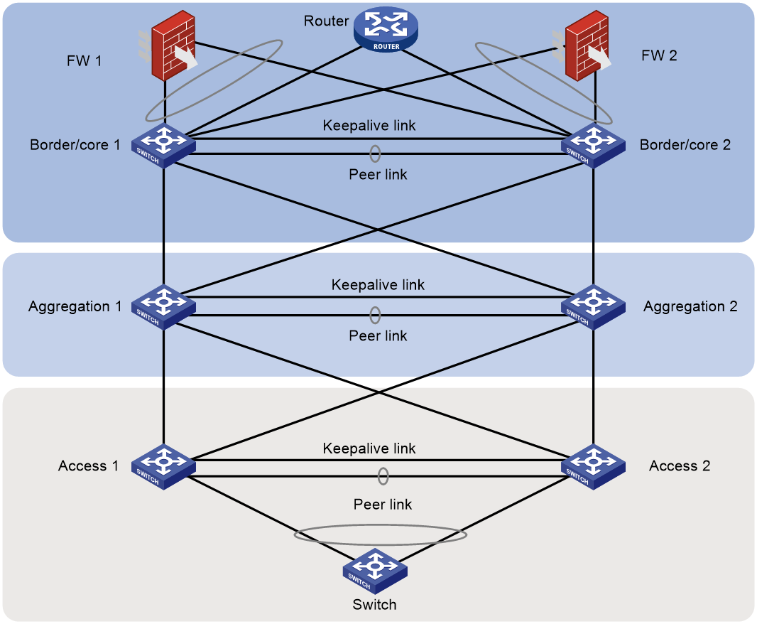
M-LAG in large campus networks
In a large campus network, M-LAG systems are deployed at the following tiers:
· Access—The access devices in M-LAG systems act as user gateways.
· Aggregation.
· Border/Core.
Equal-cost multi-path (ECMP) routes are configured as follows:
· Between the aggregation and access tiers.
· Between the core and aggregation tiers.
· Between the external routers and border gateways.
Firewalls are interconnected with border gateways by using multichassis link aggregations.
Figure 1 M-LAG in a large campus network
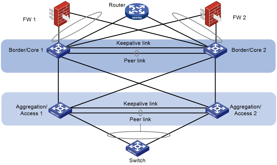
M-LAG in medium campus networks
In a medium campus network, M-LAG systems are deployed at the following tiers:
· Access/aggregation—The aggregation devices in M-LAG systems act as user gateways.
· Border/Core.
Equal-cost multi-path (ECMP) routes are configured as follows:
· Between the core and aggregation tiers.
· Between the external routers and border gateways.
Firewalls are interconnected with border gateways by using multichassis link aggregations of M-LAG.
Figure 2 M-LAG in a medium campus network
M-LAG in small campus networks
In a small campus network, M-LAG systems are deployed at the following tiers:
· Access.
· Border/Core—The core devices in M-LAG systems act as user gateways.
M-LAG is used to set up multichassis link aggregations as follows:
· Between the core and access tiers.
· Between the external routers and border gateways.
· Between the firewalls and the border devices.
Figure 3 M-LAG in a small campus network

Restrictions and guidelines for M-LAG system setup
Peer link
In addition to protocol packets, the peer link also transmits data packets between the M-LAG member devices when an uplink fails. When you set up the peer link, follow these restrictions and guidelines:
· Configure the peer-link aggregation group as follows:
¡ If an M-LAG member device is a modular device, assign at least one port on each slot to the aggregation group for the peer-link interface as a best practice. Make sure at least one member port resides on a different slot than the uplink interfaces.
¡ If an M-LAG member device is a fixed-port device with interface expansion modules, assign ports from multiple interface expansion modules to the aggregation group for the peer-link interface. Make sure at least one member port resides on a different slot than the uplink interfaces.
¡ If an M-LAG member device is a fixed-port device, assign at least two physical interfaces to the aggregation group for the peer-link interface.
· As a best practice to reduce the impact of interface flapping on upper-layer services, use the link-delay command to configure the same link delay settings on the peer-link interfaces. Do not set the link delay to 0.
· The member ports in the aggregation group for the peer-link interface must have the same speed.
· Set the link type to trunk for the interfaces facing singlehomed peer devices and the peer-link interface. This restriction ensures correct transmission of ND protocol packets over the peer link and communication between attached peer devices.
· To prevent data synchronization failure, you must set the same maximum jumbo frame length on the peer-link interfaces of the M-LAG member devices.
· If an M-LAG system is attached to a large number of servers by using non-M-LAG interfaces, take the size of the traffic sent among those servers into account when you determine the bandwidth of the peer link.
Keepalive link
The M-LAG member devices exchange keepalive packets over the keepalive link to detect multi-active collisions when the peer link is down.
As a best practice, establish a dedicated direct link between two M-LAG member devices as a keepalive link. Do not use the keepalive link for any other purposes. Make sure the M-LAG member devices have Layer 2 and Layer 3 connectivity to each other over the keepalive link.
You can use management Ethernet interfaces, Layer 3 Ethernet interfaces, Layer 3 aggregate interfaces, or interfaces with a VPN instance bound to set up the keepalive link.
As a best practice, do not use VLAN interfaces for keepalive link setup. If you have to use VLAN interfaces, remove the peer-link interfaces from the related VLANs to avoid loops.
On a modular device or fixed-port device with interface expansion modules, do not use the same module to provide interfaces for setting up the keepalive link and peer link.
For correct keepalive detection, you must exclude the physical and logical interfaces used for keepalive detection from the shutdown action by M-LAG MAD.
M-LAG interface
Assign the Layer 2 aggregate interfaces attached to the same peer device to an M-LAG group.
M-LAG interfaces in the same M-LAG group must use the different LACP system MAC addresses.
As a best practice, use the undo lacp period command to enable the long LACP timeout timer (90 seconds) on an M-LAG system.
M-LAG MAD
If the peer link fails while the keepalive link is up, the secondary M-LAG member device shuts down all its interfaces except those excluded from the shutdown action by IRF MAD and M-LAG MAD. To retain an interface in up state, exclude it from the shutdown action by M-LAG MAD. Follow these restrictions and guidelines when you exclude interfaces from the shutdown action by M-LAG MAD on the underlay network:
· By default, M-LAG MAD shuts down network interfaces after an M-LAG system splits.
· You must exclude the VLAN interfaces of the VLANs to which the M-LAG interfaces and peer-link interfaces belong.
· For correct keepalive detection, you must exclude the interfaces used for keepalive detection.
· Do not exclude the uplink Layer 3 interfaces, VLAN interfaces, or physical interfaces.
When you configure M-LAG MAD, use either of the following methods:
· To shut down all network interfaces on the secondary M-LAG member device except a few special-purpose interfaces that must be retained in up state:
¡ Set the default M-LAG MAD action to M-LAG MAD DOWN by using the m-lag mad default-action down command.
¡ Exclude interfaces from being shut down by M-LAG MAD by using the m-lag mad exclude interface command.
In some scenarios, you must retain a large number of logical interfaces (for example, VLAN interfaces, aggregate interfaces, and loopback interfaces) in up state. To simplify configuration, you can exclude all logical interfaces from the shutdown action by M-LAG MAD by using the m-lag mad exclude logical-interfaces command.
· To have the secondary M-LAG member device retain a large number of interfaces in up state and shut down the remaining interfaces:
¡ Set the default M-LAG MAD action to NONE by using the m-lag mad default-action none command.
¡ Specify network interfaces that must be shut down by M-LAG MAD by using the m-lag mad include interface command.
Restrictions and guidelines
M-LAG compatibility with third-party devices
You cannot use M-LAG interfaces for communicating with third-party devices.
M-LAG system configuration
You can assign two member devices to an M-LAG system. For the M-LAG member devices to be identified as one M-LAG system, you must configure the same M-LAG system MAC address and M-LAG system priority on them. You must assign different M-LAG system numbers to the M-LAG member devices.
Make sure each M-LAG system uses a unique M-LAG system MAC address.
To ensure correct forwarding, delete M-LAG configuration from an M-LAG member device if it leaves its M-LAG system.
When you bulk shut down physical interfaces on an M-LAG member device for service changes or hardware replacement, shut down the physical interfaces used for keepalive detection prior to the physical member ports of the peer-link interface. If you fail to do so, link flapping will occur on the member ports of M-LAG interfaces.
Peer-link interface configuration
After you configure an aggregate interface as a peer-link interface, the system automatically applies the grayed configurations, which are attribute-type configurations. To avoid issues with member ports not being able to join the aggregation group due to different attribute configurations, first add the member ports to the aggregation group and then configure the aggregation interface as a peer-link interface. This approach ensures that member ports can successfully join the aggregation group, and the aggregate interface is correctly configured as a peer-link interface.
To ensure correct Layer 3 forwarding over the peer link, you must execute the undo mac-address static source-check enable command to disable static source check on the aggregate interface assigned the peer-link interface role.
[sysname-Bridge-Aggregation11]display this
#
interface Bridge-Aggregation11
port link-type trunk
port trunk permit vlan all
port m-lag peer-link 1
undo mac-address static source-check enable
#
return
M-LAG data restoration interval
The data restoration interval set by using the m-lag restore-delay command specifies the maximum amount of time for the secondary M-LAG member device to synchronize forwarding entries such as MAC address entries with the primary M-LAG member device during M-LAG system setup. Before this timer expires, the service interfaces (excluding peer-link interfaces, management Ethernet interfaces, IRF physical interfaces, and interfaces excluded from the shutdown action) are in M-LAG MAD DOWN state. After the timer expires, the state of the service interfaces changes to up. Adjust the data restoration interval based on the size of forwarding tables. If the M-LAG member devices have small forwarding tables, reduce this interval. If the forwarding tables are large, increase this interval. By default, the data restoration interval is 30 seconds. Typically, set the data restoration interval to 300 seconds. If the ARP table of an S7500X, S10500X, or S12500G-AF switch contains about 48K entries, set this interval to 900 seconds.
GIR
Before you change an M-LAG member device back to normal mode, execute the display m-lag mad verbose command to verify that no network interfaces are in M-LAG MAD DOWN state.
MAC address table
If the M-LAG system has a large number of MAC address entries, set the MAC aging timer to a higher value than 20 minutes as a best practice. To set the MAC aging timer, use the mac-address timer aging command.
After a Layer 2 Ethernet interface joins the aggregation group of a peer-link interface, the following functions will be automatically disabled. When the interface leaves the aggregation group of the peer-link interface, these functions will be forcibly restored to the default enabled state:
· Static source check, configurable with the mac-address static source-check enable command.
· Interface-specific MAC address learning, configurable with the mac-address mac-learning enable command.
Link aggregation
Do not configure automatic link aggregation on an M-LAG system.
The aggregate interfaces in an S-MLAG group cannot be used as M-LAG interfaces or peer-link interfaces.
You cannot configure link aggregation management subnets on an M-LAG system.
When you configure an M-LAG interface, follow these restrictions and guidelines:
· The link-aggregation selected-port maximum and link-aggregation selected-port minimum commands do not take effect on an M-LAG interface.
· If you execute the display link-aggregation verbose command for an M-LAG interface, the displayed system ID contains the M-LAG system MAC address and the M-LAG system priority.
· If the reference port is a member port of an M-LAG interface, the display link-aggregation verbose command displays the reference port on both M-LAG member devices.
Port isolation
Port isolation is achieved by adding ports to an isolation group, allowing layer 2 isolation between them without considering their VLAN membership. Do not assign M-LAG interfaces and peer-link interfaces to the same port isolation group.
CFD
Do not use the MAC address of a remote MEP for CFD tests on peer-link interfaces. These tests cannot work on peer-link interfaces.
Smart Link
The M-LAG member devices in an M-LAG system must have the same Smart Link configuration.
For Smart Link to operate correctly on an M-LAG interface, do not assign the M-LAG interface and non-M-LAG interfaces to the same smart link group.
Do not assign a peer-link interface to a smart link group.
Mirroring
If you use port mirroring together with M-LAG, do not assign the source port, destination port, egress port, and reflector port for a mirroring group to two aggregation groups. If the source port is in a different aggregation group than the other ports, mirrored LACPDUs will be transmitted between aggregation groups and cause aggregate interface flapping.
M-LAG network models
Layer 2 M-LAG network models
M-LAG and spanning tree
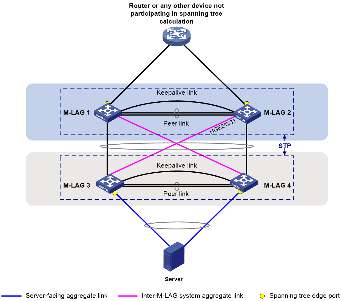
M-LAG and spanning tree
You can use M-LAG in conjunction with spanning tree to remove loops, as shown in Figure 4 and Table 2. If PVST is configured, the M-LAG member devices running PVST must be interoperable with third-party devices running Rapid PVST or PVST. If MSTP is configured, this restriction does not apply.
|
Scenario |
Solution |
Commands |
|
Due to an M-LAG system split, misconnection, or misconfiguration, traffic is sent between two member ports of the same aggregation group over the peer link, which creates a loop. |
Enable spanning tree on the M-LAG member devices. |
stp global enable (system view) undo stp enable (Interface view) |
|
A new device added to the network preempts the root bridge role, and network flapping occurs as a result. |
Configure the M-LAG member devices in the upstream M-LAG system as root bridges and enable root guard on them. |
stp root primary (system view) stp root-protection (Interface view) |
|
The M-LAG member devices are attacked by using TC-BPDUs and flush MAC address entries frequently, which causes network flapping, high CPU usage, and transient floods. |
Enable the TC-BPDU guard feature on the M-LAG member devices. |
stp tc-protection (system view) |
|
On an M-LAG member device, an interface cannot recognize BPDUs after its physical state changes. |
Configure an interface as an edge port if its peer port does not support or run spanning tree protocols. |
stp edged-port (Interface view) |
|
Network flapping occurs after an M-LAG member device receives forged BPDUs on interfaces whose counterparts do not send BPDUs. |
Enable BPDU guard on the M-LAG member device. When interfaces with BPDU guard enabled receive configuration BPDUs, the device performs the following operations: · Shuts down these interfaces. · Notifies the NMS that these interfaces have been shut down by the spanning tree protocol. The device reactivates the interfaces that have been shut down when the port status detection timer expires. |
stp bpdu-protection (system view) |
Restrictions and guidelines
Make sure the M-LAG member devices in an M-LAG system have the same spanning tree configuration. Violation of this rule might cause network flapping. The configuration includes:
· Global spanning tree configuration.
· Spanning tree configuration on the peer-link interface.
· Spanning tree configuration on M-LAG interfaces.
Peer-link interfaces of the M-LAG system do not participate in spanning tree calculation.
The M-LAG member devices still use the M-LAG system MAC address after the M-LAG system splits, which will cause spanning tree calculation issues. To avoid the issues, enable M-LAG standalone mode on the M-LAG member devices before the M-LAG system splits.
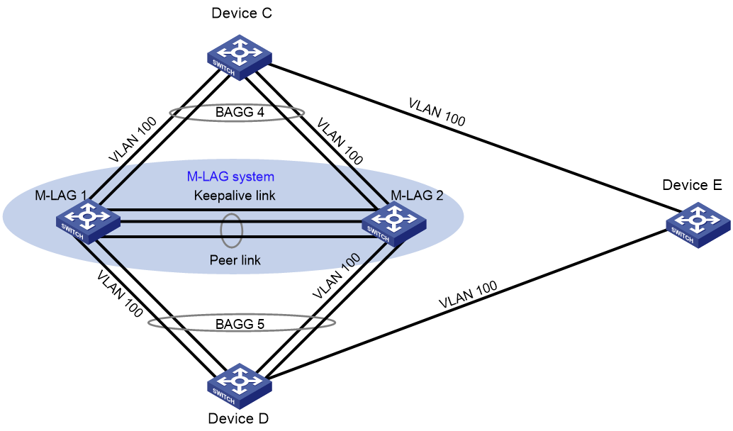
M-LAG and loop detection
A device detects loops by sending detection frames and then checking whether these frames return to any interface on the device. If they do, the device considers that the interface is on a looped link.
You can use M-LAG in conjunction with loop detection to remove loops and notify users to check the network environment, as shown in Figure 5. On M-LAG 1 and M-LAG 2, globally enable loop detection for VLAN 100 or enable loop detection for VLAN 100 on M-LAG interfaces. Device C, the M-LAG system, Device D, and Device E form a physical loop. M-LAG 1 and M-LAG 2 can detect loops on BAGG 4 and BAGG 5 and remove the loops according to the configured loop detection processing mode.
Make sure the M-LAG member devices in an M-LAG system have consistent loop detection configuration.
Layer 3 M-LAG network models
Gateway deployment schemes
Table 3 shows the schemes to configure gateways on an M-LAG system for attached endpoints.
Table 3 Gateway deployment schemes for M-LAG
|
Gateway type |
Description |
|
VLAN interface (recommended) |
A VLAN interface is configured on each M-LAG member device, and both M-LAG member devices can respond to ARP packets and perform Layer 3 forwarding. |
|
VRRP group |
Both the VRRP master and backup devices perform Layer 3 forwarding, but only the master device responds to ARP packets. In a VRRP dual-active scenario, a gateway locally forwards a packet at Layer 3 if the packet is destined for the VRRP virtual MAC address, real MAC address of the local device, or real MAC address of the M-LAG peer. The M-LAG member devices synchronize the real MAC addresses of the gateways with each other. |
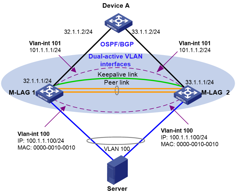
Dual-active VLAN interfaces
Configure VLAN interfaces as redundant gateways on both M-LAG member devices, as shown in Figure 6 and Table 4.
|
Tasks |
Forwarding |
|
· VLAN interface configuration: a. Create a gateway VLAN interface on each M-LAG member device for the same VLAN. b. Assign the same IP address and MAC address to the gateway VLAN interfaces. c. Create a VLAN interface on each M-LAG
member device for another VLAN, assign the peer-link interfaces to this VLAN,
and assign a unique IP address from the same subnet to each of the VLAN
interfaces. · Use Layer 3 interfaces to connect the M-LAG member devices to the upstream device, and configure ECMP routes for load sharing across the uplinks. |
· Layer 3 traffic sent by the user-side endpoints is forwarded to the dual-active gateways. · Downstream traffic from the external network to the user-side endpoints is distributed to M-LAG member devices based on ECMP routes. The M-LAG member devices forward the traffic to the user-side endpoints according to the local ARP or ND information. |
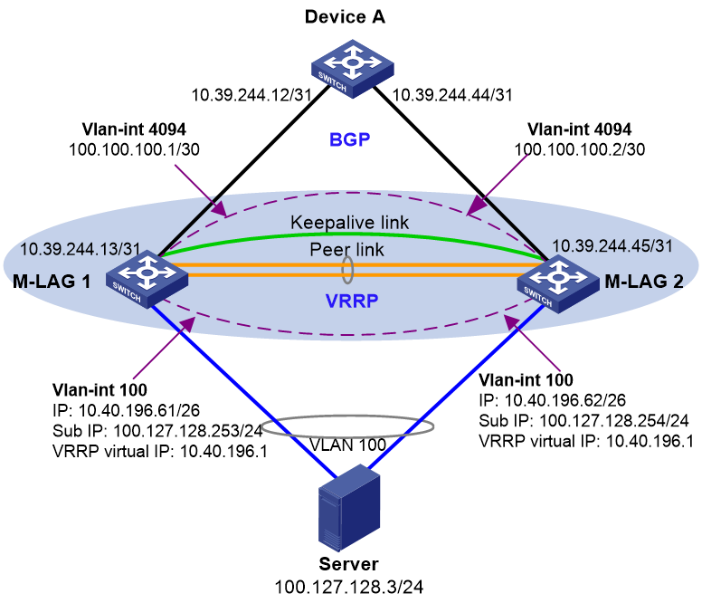
VRRP gateways
Network model
You can configure VRRP groups on an M-LAG system to provide gateway services for the attached endpoints, as shown in Figure 7 and Table 5.
|
Tasks |
Forwarding |
|
· Configure a VRRP group on the M-LAG member devices and use the VRRP virtual IP address as the gateway for the attached endpoints. · VLAN interface configuration: a. Create a VLAN interface for the VLAN where the M-LAG interface resides on each M-LAG member device. b. Assign a unique primary IP address from one subnet to each of the VLAN interfaces. · Set up a Layer 3 connection over the peer link
between the M-LAG member devices. · Use Layer 3 interfaces to connect the M-LAG member devices to the upstream device, and configure ECMP routes for load sharing across the uplinks. |
· For the Layer 3 traffic sent by the endpoints, the VRRP gateways on both M-LAG member devices can perform forwarding. · For the external traffic destined for the endpoints, the M-LAG member devices make forwarding decisions based on local ARP and ND entries. · Traffic is load shard across the uplinks and downlinks. |
Restrictions and guidelines
If you use M-LAG and VRRP together, make sure the keepalive hold timer is shorter than the interval at which the VRRP master sends VRRP advertisements. Violation of this restriction might cause a VRRP master/backup switchover to occur before peer link failure is acknowledged. To set the interval at which the VRRP master sends VRRP advertisements, use the vrrp vrid timer advertise command or the vrrp ipv6 vrid timer advertise command. To set the keepalive hold timer, use the m-lag keepalive hold-time command.
To avoid frequent master/backup switchovers, configure the routers in a VRRP group to operate in non-preemptive mode.
Restrictions and guidelines for routing configuration
Router ID
You must manually assign unique router IDs to the M-LAG member devices in an M-LAG system.
NSR
You must enable NSR for the routing protocol used on M-LAG member devices that have two MPUs.
OSPF and OSPFv3
For fast network convergence, perform the following tasks on all devices with OSPF or OSPFv3 configured:
· Execute the ospf network-type p2p or ospfv3 network-type p2p command on the interfaces that have OSPF or OSPFv3 neighbors.
· Execute the spf-schedule-interval 1 10 10 and lsa-generation-interval 1 10 10 commands in OSPF or OSPFv3 view to speed up SPF calculation and LSA generation after link failure occurs.
· Accelerate network convergence after a device reboots:
¡ In OSPF view, execute the stub-router include-stub on-startup command. For a fixed-port device, set this timeout time to 300 seconds. For a modular device, set the timeout time to be longer than 300 seconds. If all slots of a modular device have modules installed, set the timeout time to 900 seconds or longer.
¡ In OSPFv3 view, execute the stub-router max-metric include-stub on-startup command. For a fixed-port device, set this timeout time to 300 seconds. For a modular device, set the timeout time to be longer than 300 seconds. If all slots of a modular device have modules installed, set the timeout time to 900 seconds or longer.
¡ Execute the ospf peer hold-max-cost duration or ospfv3 peer hold-max-cost duration command to advertise the maximum link cost to neighbors within the specified period if the routing table is large or network convergence is slow on peer devices.
IPv4 ISIS and IPv6 ISIS
Execute the isis peer hold-max-cost duration command to advertise the maximum link cost to neighbors within the specified period if the routing table is large or network convergence is slow on peer devices.
BGP
If the routing table is large or network convergence is slow on peer devices, perform the following tasks:
· Use the bgp apply-policy on-startup duration seconds command to specify the period after reboot within which the startup policy is effective.
· Use the bgp policy on-startup med command to set the MED attribute value in the startup policy. The MED attribute value must be larger than the time required to set up a peer relationship.
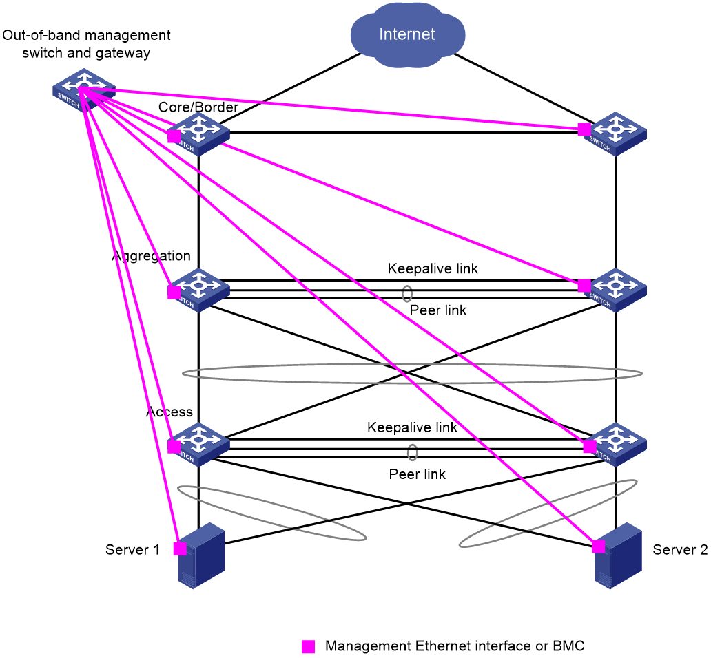
Management network design
As a best practice to prevent forwarding faults from interrupting device management, use management Ethernet interfaces to connect devices to a management network for out-of-band management. Table 6 shows the number of management Ethernet interfaces on the campus devices.
In an M-LAG system, all management Ethernet interfaces on both M-LAG member devices are available. You need to manage the M-LAG member devices separately.
Table 6 Number of management Ethernet interfaces on campus devices
|
Devices providing two or more management Ethernet interfaces |
Devices providing one management Ethernet interface |
|
· S12500G-AF series · S10500 series · S10500X series · S7500E series · S7500X series · S7600E-X series · S7600-X series · S7600 series · S10500X-G series · S7500X-G series · S6550XE-HI series · S6525XE-HI series |
· S6520X-EI · S6520X-HI · S5590-HI · S5590-EI · S5560X-HI · S5560X-EI · S5590XP-HI-G · S6520X-EI-G · S6520XP-EI-G · S6805-G · S6850-G · S6530X · S9850-G |
Figure 8 shows the management network topology for a campus network. The border, core, aggregation, and acess devices are attached to the out-of-band management switch by using management Ethernet interfaces. The switch provides gateway services.
Figure 8 Out-of-band management
High availability for M-LAG
High availability of uplinks
You can use the following methods to ensure high availability of uplinks:
· Configure routes—Create one VLAN interface on each M-LAG member device, and set up routing neighbor relationships over the peer link between the VLAN interfaces. When the uplink on an M-LAG member device fails, the device sends its traffic over the peer link for the other M-LAG member device to forward.
¡ If an M-LAG system is attached to standalone upstream devices and ECMP routes are configured for load sharing across the uplinks, you need to interconnect the M-LAG member devices through routing. The Layer 3 connections will be used to transmit traffic between the M-LAG member devices in case of uplink failure.
¡ If an M-LAG system operating at Layer 2 is attached to an upstream M-LAG system, you do not need to interconnect the M-LAG member devices through routing.
· Configure Monitor Link—Associate the M-LAG interfaces with the uplink interfaces. When the uplink interface of an M-LAG member device fails, that device shuts down its M-LAG interface for the other M-LAG member device to forward all traffic. Use this method if the peer link forwards heavy traffic and has bandwidth bottlenecks.
High availability schemes
Figure 9 and Table 7 show the high availability schemes for an M-LAG network.
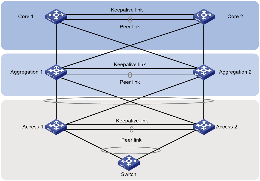
Table 7 M-LAG high availability schemes
|
Scenario |
Impact |
High availability scheme |
|
M-LAG device failure |
· When an M-LAG member device restarts, traffic is switched to its M-LAG peer. · After the restarted M-LAG member device joins the M-LAG system, the following events occur: a. The peer link comes up. b. The M-LAG peer sends its MAC address entries and ARP entries over the peer link to the restarted M-LAG member device. c. The restarted M-LAG member device brings up the member ports of the M-LAG interfaces when the data restoration interval set by using the m-lag restore-delay command expires. d. The restarted M-LAG member device brings up all service interfaces after forwarding entries are refreshed for all interfaces. |
N/A |
|
Service module failure |
If the uplink or downlinks are connected to different service modules on an M-LAG member device, when a service module fails, traffic will switch to the other service modules. If no available links are present on the other service modules, the traffic will be processed by the M-LAG peer. |
If an M-LAG member device have multiple service modules or interface expansion modules, connect the uplinks and downlinks to different service modules or interface expansion modules. Make sure the uplinks or downlinks are not connected to multiple modules. |
|
ECMP link failure |
· If the link between Aggregation 1 and Core 1 fails, uplink traffic is switched to Core 2. · If all links between Aggregation 1 and the core devices are down, traffic is sent over the peer link to Aggregation 2. |
N/A |
|
Multichassis aggregate link failure |
· The switch is dualhomed to the access devices. If a member link of the multichassis aggregate link fails, traffic is switched to the other member link. When the failed member link recovers, traffic is switched back to it. · If the link between Access 1 and Aggregation 1 fails, uplink traffic is switched to Aggregation 2. · If all links between Access 1 and the aggregation devices are down, traffic is sent over the peer link to Access 2. |
- |
|
Keepalive link failure |
Keepalive link failure does not affect traffic forwarding. This link is used for multi-active collision detection only when a device or the peer link fails. |
Exclude the interfaces used for keepalive detection from the shutdown action by M-LAG MAD. |
|
Peer link failure |
· The secondary aggregation device places its uplink and downlink interfaces in M-LAG MAD DOWN state to switch traffic to the other aggregation device. · After the peer link recovers, the interfaces in M-LAG MAD DOWN state are brought up after the data restoration interval set by using the m-lag restore-delay command expires. Then, traffic is switched back to the secondary aggregation device. |
Use interfaces from multiple modules or submodules to set up the peer link. |
|
Concurrent peer link and keepalive link failures |
If the keepalive link goes down before the peer link goes down, the following events occur: 1. The M-LAG member devices are placed in M-LAG standalone mode. 2. Only one M-LAG member device has selected aggregation member ports and forwards traffic. If the peer link goes down before the keepalive link goes down, the following events occur: 1. When the peer link does down, the secondary M-LAG member device places its interfaces in M-LAG MAD DOWN state. 2. When the keepalive link goes down, the secondary M-LAG member device brings up its interfaces in M-LAG MAD DOWN state. The M-LAG member devices are placed in M-LAG standalone mode. Only one M-LAG member device has selected aggregation member ports and forwards traffic. |
· Enable M-LAG standalone mode on the leaf devices by using the m-lag standalone enable command. · Configure the LACP system ID by using one of the following methods: ¡ Execute the lacp system-mac and lacp system-priority commands in system view. ¡ Execute the port lacp system-mac and port lacp system-priority commands in Layer 2 aggregate interface view. |
Recommended hardware and software versions
You must install the latest patches (if any) for the recommended software versions on all devices.
If the hardware and software versions listed in the following matrix conflict with those used in configuration examples, use the hardware and software versions in the configuration examples. If you have any doubts, contact H3C Support.
Table 8 shows the recommended hardware and software versions for different scales of campus networks.
Table 8 Recommended hardware and software versions
|
Device role |
Scenario |
Hardware |
Software version |
|
Border/core |
Medium and large networks |
· S12500G-AF (type T cards) · S10500 · S10500X |
R7625 and later |
|
· S12500G-AF (type S cards) |
R8054P04 and later |
||
|
· S10500X-G |
R7754P04 and later |
||
|
Small networks |
· Same as the aggregation devices |
Same as the aggregation devices |
|
|
Aggregation |
Medium and large networks |
· S12500G-AF (type T cards) · S10500 · S10500X · S7500E · S7500X · S7600E-X · S7600-X · S7600 |
R7625 and later |
|
· S12500G-AF (type S cards) |
R8054P04 and later |
||
|
· S10500X-G · S7500X-G |
R7754P04 and later |
||
|
Small networks |
· Same as the access devices |
Same as the access devices |
|
|
Access |
10GE access connection |
· S7500E · S7500X · S7600 · S7600-X |
R7625 and later |
|
· GE access connection · 10GE access connection |
· S6550XE-HI · S6525XE-HI |
R8106P22 and later |
|
|
· 10GE access connection |
· S6520X-EI · S6520X-HI |
F6628P11 and later |
|
|
· 10GE access connection |
· S6520X-EI-G · S6520XP-EI-G |
R7754P04 and later |
|
|
· GE access connection · 10GE access connection |
· S5590-HI · S5590-EI |
R8307P08 and later |
|
|
· 10GE access connection · 25GE access connection · 100GE access connection |
· S6530X |
R8307P08 and later |
|
|
· 10GE access connection · 100GE access connection |
· S6805-G |
R8307P08 and later |
|
|
· 25GE access connection · 100GE access connection |
· S6850-G |
R8307P08 and later |
|
|
· 100GE access connection · 400GE access connection |
· S9850-G |
R8307P08 and later |
|
|
· GE access connection · 10GE access connection |
· S5590XP-HI-G |
R7754P04 and later |
|
|
· GE access connection · 10GE access connection |
· S5560X-HI |
F6628P11 and later |
|
|
· GE access connection · 10GE access connection |
· S5560X-EI |
F6628P11 and later |
