- Table of Contents
-
- H3C Campus Switches M-LAG Configuration Guide-6W101
- 00-M-LAG network planning for campus networks
- 01-M-LAG and VRRP Configuration Example (Campus)
- 02-M-LAG + Spanning Tree Configuration Example (Campus)
- 03-Dual-Active VLAN Gateway Configuration Example (Campus)
- 04-M-LAG and Loop Detection Configuration Example (Campus)
- 05-Multi-Tier M-LAG and VRRP Configuration Example (Campus)
- 06-M-LAG + VXLAN Distributed Gateway Network Configuration Example (Ethernet Aggregate Link as Peer Link) (Campus)
- 07-M-LAG + EVPN VXLAN Centralized Gateway Network Configuration Example (Ethernet Aggregate Link as Peer Link) (Campus)
- 08-M-LAG and MPLS L3VPN Configuraion Example (Campus)
- 09-M-LAG and Mirroring Configuration Example (Campus)
- Related Documents
-
| Title | Size | Download |
|---|---|---|
| 02-M-LAG + Spanning Tree Configuration Example (Campus) | 361.02 KB |
Example: Configuring M-LAG + spanning tree (campus)
Configuring Device E or Device F
Configure M-LAG member devices
Configuring Device E and Device F
Overlay traffic characteristics
Example: Configuring M-LAG + spanning tree (campus)
Network configuration
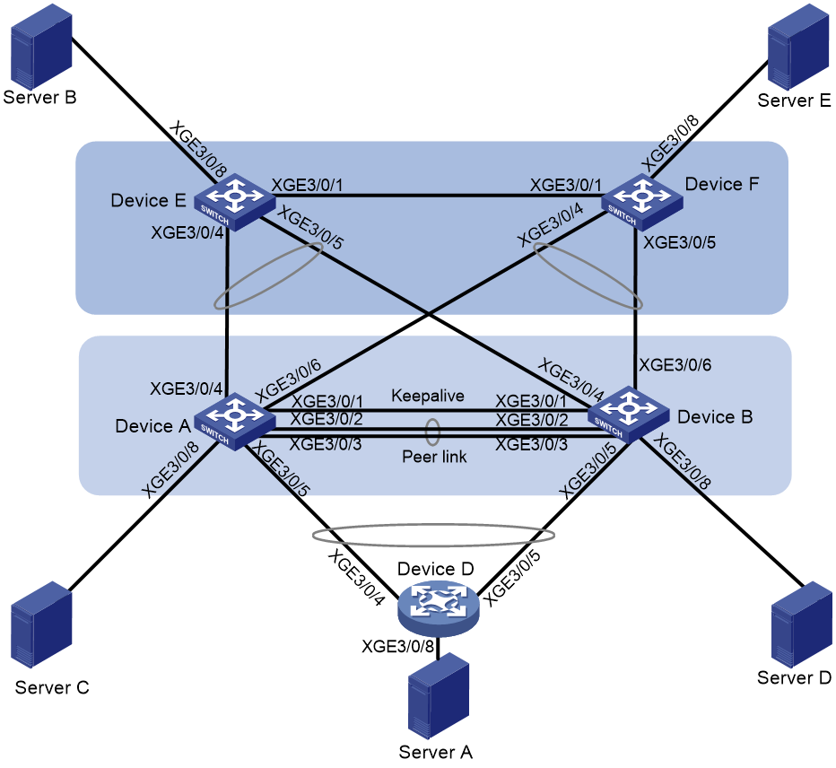
As shown in Figure 1:
· Set up an M-LAG system with Device A and Device B. Device D, Device E and Device F are connected to the M-LAG system via the M-LAG interfaces.
· Server A is dualhomed to the network through M-LAG.
· Server A, Server B, Server C, Server D, and Server E belong to the same network segment.
Application scenarios and user requirements for spanning tree are as follows:
· All services can communicate at layer 2.
· When a link on the M-LAG member devices fails, the servers still can communicate at Layer 2.
· When an M-LAG member device fails, the servers still can communicate at Layer 2.
|
Device |
Interface |
IP address |
Remarks |
|
Device A |
XGE 3/0/4 |
N/A |
Device E: XGE 3/0/4 Member interface of an M-LAG aggregation group |
|
XGE 3/0/6 |
N/A |
Device F: XGE 3/0/4 Member interface of an M-LAG aggregation group |
|
|
XGE 3/0/1 |
21.1.1.1/24 |
Device B: XGE 3/0/1 Keepalive link between M-LAG member devices. |
|
|
XGE 3/0/2 |
N/A |
Device B: XGE 3/0/2 Member interface of the peer-link aggregation group |
|
|
XGE 3/0/3 |
N/A |
Device B: XGE 3/0/3 Member interface of the peer-link aggregation group |
|
|
XGE 3/0/5 |
N/A |
Device D: XGE 3/0/4 Member interface of an M-LAG aggregation group |
|
|
XGE 3/0/8 |
N/A |
Server C |
|
|
Device B |
XGE 3/0/4 |
N/A |
Device E XGE 3/0/5 Member interface of an M-LAG aggregation group |
|
XGE 3/0/6 |
N/A |
Device F: XGE 3/0/5 Member interface of an M-LAG aggregation group |
|
|
XGE 3/0/1 |
21.1.1.2/24 |
Device A: XGE 3/0/1 Keepalive link between M-LAG member devices. |
|
|
XGE 3/0/2 |
N/A |
Device A: XGE 3/0/2 Member interface of the peer-link aggregation group |
|
|
XGE 3/0/3 |
N/A |
Device A: XGE 3/0/3 Member interface of the peer-link aggregation group |
|
|
XGE 3/0/5 |
N/A |
Device D: XGE 3/0/5 Member interface of an M-LAG aggregation group |
|
|
XGE 3/0/8 |
N/A |
Server D |
|
|
Device E |
XGE 3/0/4 |
N/A |
Device A: XGE 3/0/4 |
|
XGE 3/0/5 |
N/A |
Device B: XGE 3/0/4 |
|
|
XGE 3/0/1 |
N/A |
Device F: XGE 3/0/1 |
|
|
XGE 3/0/8 |
N/A |
Server B |
|
|
Device F |
XGE 3/0/4 |
N/A |
Device A: XGE 3/0/6 |
|
XGE 3/0/5 |
N/A |
Device B: XGE 3/0/6 |
|
|
XGE 3/0/1 |
N/A |
Device F: XGE 3/0/1 |
|
|
XGE 3/0/8 |
N/A |
Server E |
|
|
Device D |
XGE 3/0/4 |
N/A |
Device A: XGE 3/0/5 |
|
XGE 3/0/5 |
N/A |
Device B: XGE 3/0/5 |
|
|
XGE 3/0/8 |
N/A |
Server A |
Applicable product matrix
|
|
IMPORTANT: In addition to running an applicable software version, you must also install the most recent patch, if any. |
|
Device |
Software version |
|
S10500, S10500X, S7600, S7600-X, S7600E-X, S7500X, S7500E |
R7625 and later |
|
S12500G-AF (type T cards) |
R7625 and later |
|
S12500G-AF (type S cards) |
R8054P04 and later |
|
S10500X-G, S7500X-G |
R7754P04 and later |
|
S5590XP-HI-G, S6520X-EI-G, S6520XP-EI-G |
R7754P04 and later |
|
S6550XE-HI, S6525XE-HI |
R8106P22 and later |
|
S6520X-EI, S6520X-HI |
F6628P11 and later |
|
S5590-HI, S5590-EI, S6805-G, S6850-G, S6530X, S9850-G |
R8307P08 and later |
|
S5560X-HI |
F6628P11 and later |
|
S5560X-EI |
F6628P11 and later |
Analysis
· Configure Device A and Device B as an M-LAG system. Both uplink and downlink interfaces are assigned to M-LAG groups and interconnected with Device E, Device F and Device D. Device E and Device F are interconnected with each other.
· MSTP or PVST are enabled on all devices. MSTP mode and PVST mode are configured separately. If PVST mode is configured, then the M-LAG member device running PVST must communicate with third-party devices running Rapid PVST or PVST. If MSTP mode is configured, this requirement is not necessary.
Restrictions and guidelines
All devices in this example were started with the factory default configuration. When you are working on a live network, make sure you understand the potential impact of every command on your network.
When enabling MSTP or PVST on all devices, make sure that MSTP mode and PVST mode are configured separately.
Configuring MSTP
Configuring the M-LAG system
Procedure summary
1. Setting up the M-LAG system
2. Configuring interconnect links between the M-LAG member devices and Device D
3. Configuring interconnect links between the M-LAG member devices and Device E or Device F
4. Configuring interconnect links between the M-LAG member devices and singlehomed devices
Setting up the M-LAG system
|
Device A |
Device B |
Description |
Remarks |
|
m-lag system-mac 2-2-2 |
m-lag system-mac 2-2-2 |
Set the M-LAG system MAC address. |
You must set the same M-LAG system MAC address for devices in the same M-LAG system. |
|
m-lag system-number 1 |
m-lag system-number 2 |
Set the M- LAG system number. |
You must set different M-LAG system numbers for devices in the same M-LAG system. |
|
m-lag system-priority 123 |
m-lag system-priority 123 |
Set the M-LAG system priority. |
You must set the same M-LAG system priority for devices in the same M-LAG system. |
|
m-lag standalone enable |
m-lag standalone enable |
(Optional.) Enable M-LAG standalone mode. |
The M-LAG member devices might both operate with the primary role to forward traffic after the M-LAG system splits. M-LAG standalone mode helps avoid traffic forwarding issues in this multi-active situation. |
|
m-lag keepalive ip destination 21.1.1.2 source 21.1.1.1 |
m-lag keepalive ip destination 21.1.1.1 source 21.1.1.2 |
Configure the destination and source IP addresses of keepalive packets. |
N/A |
|
interface Ten-gigabitethernet3/0/1 |
interface Ten-gigabitethernet3/0/1 |
Enter the view of the keepalive interface. |
N/A |
|
port link-mode route |
port link-mode route |
Configure the keepalive interface to operate in Layer 3 mode. |
N/A |
|
ip address 21.1.1.1 24 |
ip address 21.1.1.2 24 |
Assign source IPv4 address of keepalive packets to the keepalive interface. |
N/A |
|
quit |
quit |
Return to system view. |
N/A |
|
m-lag mad exclude interface Ten-gigabitethernet3/0/1 |
m-lag mad exclude interface Ten-gigabitethernet3/0/1 |
Exclude the interface used for M-LAG keepalive detection from the shutdown action by M-LAG MAD. |
N/A |
|
interface bridge-aggregation 1 |
interface bridge-aggregation 1 |
Create the Layer 2 aggregate interface to be used as the peer-link interface and enter interface view. |
N/A |
|
link-aggregation mode dynamic |
link-aggregation mode dynamic |
Configure the aggregate interface to operate in dynamic mode. |
N/A |
|
quit |
quit |
Return to system view. |
N/A |
|
interface range Ten-gigabitethernet 3/0/2 Ten-gigabitethernet 3/0/3 |
interface range Ten-gigabitethernet 3/0/2 Ten-gigabitethernet 3/0/3 |
Enter the view of physical interfaces on the peer link. |
N/A |
|
port link-aggregation group 1 |
port link-aggregation group 1 |
Assign the physical interfaces on the peer link to the aggregation group for the peer link. |
N/A |
|
quit |
quit |
Return to system view. |
N/A |
|
interface bridge-aggregation 1 |
interface bridge-aggregation 1 |
Enter aggregate interface view. |
N/A |
|
port m-lag peer-link 1 |
port m-lag peer-link 1 |
Specify Bridge-Aggregation 1 as the peer-link interface. |
N/A |
|
undo mac-address static source-check enable |
undo mac-address static source-check enable |
Disable the static source check feature to avoid inter-peer link Layer 3 traffic forwarding failures. |
N/A |
|
quit |
quit |
Return to system view. |
N/A |
Configuring interconnect links between the M-LAG member devices and Device D
|
Device A |
Device B |
Description |
Remarks |
|
interface bridge-aggregation 2 |
interface bridge-aggregation 2 |
Create an aggregate interface connected to Device D. |
N/A |
|
link-aggregation mode dynamic |
link-aggregation mode dynamic |
Configure the aggregate group to operate in dynamic mode. |
N/A |
|
port m-lag group 1 |
port m-lag group 1 |
Assign Bridge-Aggregation 2 to M-LAG group 1. |
N/A |
|
quit |
quit |
Return to system view. |
N/A |
|
interface Ten-gigabitethernet 3/0/5 |
interface Ten-gigabitethernet 3/0/5 |
Enter the view of the physical interface facing Device D. |
N/A |
|
port link-aggregation group 2 |
port link-aggregation group 2 |
Assign the interface to an aggregation group. |
N/A |
|
quit |
quit |
Return to system view. |
N/A |
|
vlan 1001 1002 |
vlan 1001 1002 |
Create a VLAN. |
N/A |
|
interface bridge-aggregation 2 |
interface bridge-aggregation 2 |
Enter aggregate interface view. |
N/A |
|
port link-type trunk |
port link-type trunk |
Configure Bridge-Aggregation 2 as a trunk port. |
N/A |
|
port trunk permit vlan 1001 1002 |
port trunk permit vlan 1001 1002 |
Allow packets for the specified VLAN to pass. |
N/A |
|
port lacp system-priority 100 |
port lacp system-priority 101 |
Set the LACP priority. |
The two devices need to be configured with different LACP priorities so that only the high priority member port (the smaller the value, the higher the priority) is selected in case of brain split (the keepalive link and peer-link link fail at the same time). |
|
quit |
quit |
Return to system view. |
N/A |
Configuring interconnect links between the M-LAG member devices and Device E or Device F
|
Device A |
Device B |
Description |
Remarks |
|
interface bridge-aggregation 101 |
interface bridge-aggregation 101 |
Create the aggregate interface connecting to Device E. |
N/A |
|
link-aggregation mode dynamic |
link-aggregation mode dynamic |
Configure the aggregate interface to operate in dynamic mode. |
N/A |
|
port m-aggregation group 101 |
port m-lag group 101 |
Assign the aggregate interface 101 to M-LAG group 101. |
N/A |
|
quit |
quit |
Return to system view. |
N/A |
|
interface Ten-gigabitethernet 3/0/4 |
interface Ten-gigabitethernet 3/0/4 |
Enter the view of the physical interface connecting the M-LAG system to Device E. |
N/A |
|
port link-aggregation group 101 |
port link-aggregation group 101 |
Assign the interface to an aggregation group. |
N/A |
|
quit |
quit |
Return to system view. |
N/A |
|
interface bridge-aggregation 102 |
interface bridge-aggregation 102 |
Create the aggregate interface connecting to Device F. |
N/A |
|
link-aggregation mode dynamic |
link-aggregation mode dynamic |
Configure the aggregate interface to operate in dynamic mode. |
N/A |
|
port m-lag group 102 |
port m-lag group 102 |
Assign the aggregate interface 102 to M- LAG group 102. |
N/A |
|
quit |
quit |
Return to system view. |
N/A |
|
interface Ten-gigabitethernet 3/0/6 |
interface Ten-gigabitethernet 3/0/6 |
Enter the view of the physical interface connecting the M-LAG system to Device F. |
N/A |
|
port link-aggregation group 102 |
port link-aggregation group 102 |
Assign the interface to an aggregation group. |
N/A |
|
quit |
quit |
Return to system view. |
N/A |
|
interface range bridge-aggregation 101 bridge-aggregation 102 |
interface range bridge-aggregation 101 bridge-aggregation 102 |
Enter aggregate interface group view. |
N/A |
|
port link-type trunk |
port link-type trunk |
Configure Bridge-Aggregation 2 as a trunk port. |
N/A |
|
port trunk permit vlan 1001 1002 |
port trunk permit vlan 1001 1002 |
Allow packets for the specified VLAN to pass. |
N/A |
|
port lacp system-priority 100 |
port lacp system-priority 101 |
Configure the LACP priority. |
The two devices need to be configured with different LACP priorities so that only the high priority member port (the smaller the value, the higher the priority) is selected in case of brain split (the keepalive link and peer-link link fail at the same time). |
|
quit |
quit |
Return to system view. |
N/A |
Configuring interconnect links between the M-LAG member devices and singlehomed devices
|
Device A |
Device B |
Description |
Remarks |
|
interface Ten-gigabitethernet 3/0/8 |
interface Ten-gigabitethernet 3/0/8 |
Enter Ethernet interface view. |
N/A |
|
port link-type trunk |
port link-type trunk |
Configure Bridge-Aggregation 2 as a trunk port. |
N/A |
|
port trunk permit vlan 1001 1002 |
port trunk permit vlan 1001 1002 |
Allow packets for the specified VLAN to pass. |
N/A |
|
quit |
quit |
Return to system view. |
N/A |
Configuring MSTP
|
Device A |
Device B |
Description |
Remarks |
|
stp global enable |
stp global enable |
Enable the spanning tree protocol globally. |
|
|
stp region-configuration |
stp region-configuration |
Configure an MST region. |
|
|
region-name test |
region-name test |
Configure an MST region name. |
|
|
interface vlan-interface 1001 |
interface vlan-interface 1001 |
Create VLAN-interface 1001. |
|
|
instance 2 vlan 1002 |
instance 2 vlan 1002 |
Map the VLAN to MSTI 2. |
|
|
active region-configuration |
active region-configuration |
Activate the MST region. |
|
|
quit |
quit |
Return to system view. |
|
|
stp instance 1 root primary |
stp instance 1 root primary |
Configure the switch as the root bridge in MSTI 1. |
|
|
stp instance 2 root primary |
stp instance 2 root primary |
Configure the switch as the root bridge in MSTI 2. |
|
|
interface bridge-aggregation 101 |
interface bridge-aggregation 101 |
Enter aggregate interface view. |
|
|
stp instance 1 cost 10 |
stp instance 1 cost 10 |
Configure the path cost of the port in MSTI 1. |
You can enable flows of different instances to travel along different physical links by configuring different path cost values for the same port in different MSTIs, so that load sharing can be implemented. |
|
stp instance 2 cost 100 |
stp instance 2 cost 100 |
Configure the path cost of the port in MSTI 2. |
|
|
quit |
quit |
Return to system view. |
|
|
interface bridge-aggregation 102 |
interface bridge-aggregation 102 |
Enter aggregate interface view. |
|
|
stp instance 1 cost 100 |
stp instance 1 cost 100 |
Configure the path cost of the port in MSTI 1. |
You can enable flows of different instances to travel along different physical links by configuring different path cost values for the same port in different MSTIs, so that load sharing can be implemented. |
|
stp instance 2 cost 10 |
stp instance 2 cost 10 |
Configure the path cost of the port in MSTI 2. |
|
|
quit |
quit |
Return to system view. |
|
|
interface Ten-gigabitethernet 3/0/8 |
interface Ten-gigabitethernet 3/0/8 |
Enter Ethernet interface view. |
|
|
stp edged-port |
stp edged-port |
Configure the ports as spanning tree edge ports. |
|
|
quit |
quit |
Return to system view. |
|
Configuring Device E or Device F
Procedure summary
1. Configuring the interconnect links between the M-LAG member devices and Device E or Device F
2. Configuring the interconnect links between Device E and Device F
3. Configuring the links connecting Device E and Device F to the endpoint
Configuring the interconnect links between the M-LAG member devices and Device E or Device F
|
Device E |
Device F |
Description |
Remarks |
|
vlan 1001 1002 |
vlan 1001 1002 |
Create a VLAN. |
N/A |
|
interface bridge-aggregation 101 |
interface bridge-aggregation 102 |
Create the aggregate interface connecting to M-LAG. |
N/A |
|
link-aggregation mode dynamic |
link-aggregation mode dynamic |
Configure the aggregate interface to operate in dynamic mode. |
N/A |
|
quit |
quit |
Return to system view. |
N/A |
|
interface range Ten-gigabitethernet 3/0/4 Ten-gigabitethernet 3/0/5 |
interface range Ten-gigabitethernet 3/0/4 Ten-gigabitethernet 3/0/5 |
Enter physical port group view. |
N/A |
|
port link-aggregation group 101 |
port link-aggregation group 102 |
Assign the interface to an aggregation group. |
N/A |
|
quit |
quit |
Return to system view. |
N/A |
|
interface bridge-aggregation 101 |
interface bridge-aggregation 102 |
Enter aggregate interface view. |
N/A |
|
port link-type trunk |
port link-type trunk |
Configure Bridge-Aggregation 2 as a trunk port. |
N/A |
|
port trunk permit vlan 1001 1002 |
port trunk permit vlan 1001 1002 |
Allow packets for the specified VLAN to pass. |
N/A |
|
quit |
quit |
Return to system view. |
N/A |
Configuring the interconnect links between Device E and Device F
|
Device E |
Device F |
Description |
Remarks |
|
interface Ten-gigabitethernet 3/0/1 |
interface Ten-gigabitethernet 3/0/1 |
Enter Ethernet interface view. |
N/A |
|
port link-type trunk |
port link-type trunk |
Configure Bridge-Aggregation 2 as a trunk port. |
N/A |
|
port trunk permit vlan 1001 1002 |
port trunk permit vlan 1001 1002 |
Allow packets for the specified VLAN to pass. |
N/A |
|
quit |
quit |
Return to system view. |
N/A |
|
interface Ten-gigabitethernet 3/0/8 |
interface Ten-gigabitethernet 3/0/8 |
Enter Ethernet interface view. |
N/A |
|
port link-type trunk |
port link-type trunk |
Configure Bridge-Aggregation 2 as a trunk port. |
N/A |
|
port trunk permit vlan 1001 1002 |
port trunk permit vlan 1001 1002 |
Allow packets for the specified VLAN to pass. |
N/A |
|
quit |
quit |
Return to system view. |
N/A |
Configuring the links connecting Device E and Device F to the endpoint
|
Device E |
Device F |
Description |
Remarks |
|
interface Ten-gigabitethernet 3/0/8 |
interface Ten-gigabitethernet 3/0/8 |
Enter Ethernet interface view. |
N/A |
|
port link-type trunk |
port link-type trunk |
Configure Bridge-Aggregation 2 as a trunk port. |
N/A |
|
port trunk permit vlan 1001 1002 |
port trunk permit vlan 1001 1002 |
Allow packets for the specified VLAN to pass. |
N/A |
|
quit |
quit |
Return to system view. |
N/A |
Configuring MSTP
|
Device E |
Device F |
Description |
Remarks |
|
stp global enable |
stp global enable |
Enable the spanning tree feature globally. |
MSTP configuration is independent of PVST configuration. |
|
stp region-configuration |
stp region-configuration |
Configure an MST region. |
N/A |
|
region-name test |
region-name test |
Configure an MST region name. |
N/A |
|
instance 1 vlan 1001 |
instance 1 vlan 1001 |
Mapping a VLAN to MSTI 1. |
N/A |
|
instance 2 vlan 1002 |
instance 2 vlan 1002 |
Map a VLAN to MSTI 2. |
N/A |
|
active region-configuration |
active region-configuration |
Activate the MST region. |
N/A |
|
quit |
quit |
Return to system view. |
N/A |
|
interface bridge-aggregation 101 |
interface bridge-aggregation 102 |
Enter aggregate interface view. |
N/A |
|
stp instance 1 cost 10 |
stp instance 1 cost 100 |
Configure the path cost of the port in MSTI 1. |
You can enable flows of different VLANs to travel along different physical links by configuring different path cost values for the same port in different MSTIs, so that load balancing can be implemented. |
|
stp instance 2 cost 100 |
stp instance 2 cost 10 |
Configure the path cost of the port in MSTI 2. |
|
|
quit |
quit |
Return to system view. |
N/A |
|
interface Ten-gigabitethernet 3/0/1 |
interface Ten-gigabitethernet 3/0/1 |
Enter Ethernet interface view. |
N/A |
|
stp instance 1 cost 100 |
stp instance 1 cost 200 |
Set the path cost of the interface in MSTI 1. |
You can enable flows of different instances to travel along different physical links by configuring different path cost values for the same port in different MSTIs, so that load sharing can be implemented. |
|
stp instance 2 cost 100 |
stp instance 2 cost 200 |
Set the path cost of the interface in MSTI 2. |
|
|
quit |
quit |
Return to system view. |
N/A |
|
interface Ten-gigabitethernet 3/0/8 |
interface Ten-gigabitethernet 3/0/8 |
Enter Ethernet interface view. |
N/A |
|
stp edged-port |
stp edged-port |
Configure the ports as spanning tree edge ports. |
N/A |
|
quit |
quit |
Return to system view. |
N/A |
Configuring Device D
Procedure summary
1. Configuring the interconnect links between the M-LAG member devices and Device D
Configuring the interconnect links between the M-LAG member devices and Device D
|
Device D |
Description |
|
vlan 1001 1002 |
Create a VLAN. |
|
interface bridge-aggregation 2 |
Create an aggregate interface to connect to the M-LAG system. |
|
link-aggregation mode dynamic |
Configure an aggregate interface to operate in dynamic mode. |
|
quit |
Return to system view. |
|
interface range Ten-gigabitethernet 3/0/4 to Ten-gigabitethernet 3/0/5 |
Enter the view of the physical port group connected to the M-LAG system. |
|
port link-aggregation group 2 |
Assign the interface to an aggregation group. |
|
quit |
Return to system view. |
|
interface bridge-aggregation 2 |
Enter aggregate interface view. |
|
port link-type trunk |
Configure Bridge-Aggregation 2 as a trunk port. |
|
port trunk permit vlan 1001 1002 |
Allow packets for the specified VLAN to pass. |
|
quit |
Return to system view. |
|
interface Ten-gigabitethernet 3/0/8 |
Enter Ethernet interface view. |
|
port link-type trunk |
Configure Bridge-Aggregation 2 as a trunk port. |
|
port trunk permit vlan 1001 1002 |
Allow packets for the specified VLAN to pass. |
|
quit |
Return to system view. |
Configuring MSTP
|
Device D |
Description |
Remarks |
|
stp global enable |
Enable the spanning tree feature globally. |
MSTP configuration is independent of PVST configuration. |
|
stp region-configuration |
Configure an MST region. |
N/A |
|
region-name test |
Configure an MST region name. |
N/A |
|
instance 1 vlan 1001 |
Map a VLAN to MSTI 1. |
N/A |
|
instance 2 vlan 1002 |
Map a VLAN to MSTI 2. |
N/A |
|
active region-configuration |
Activate the MST region. |
N/A |
|
quit |
Return to system view. |
N/A |
|
interface Ten-gigabitethernet 3/0/8 |
Enter Ethernet interface view. |
N/A |
|
stp edged-port |
Configure the ports as spanning tree edge ports. |
N/A |
|
quit |
Return to system view. |
N/A |
Configure PVST
Configure M-LAG member devices
The configuration is the same as "Configuring MSTP" except for PVST configuration.
Configuring PVST
|
Device A |
Device B |
Description |
Remarks |
|
stp global enable |
stp global enable |
Enable the spanning tree feature globally. |
PVST configuration is independent of MSTP configuration. |
|
stp mode pvst |
stp mode pvst |
Set the spanning tree mode to PVST. |
N/A |
|
stp vlan 1001 root primary |
stp vlan 1001 root primary |
Configure the switch as a root bridge in VLAN 1001. |
N/A |
|
stp vlan 1002 root primary |
stp vlan 1002 root primary |
Configure the switch as a root bridge in VLAN 1002. |
N/A |
|
interface bridge-aggregation 101 |
interface bridge-aggregation 101 |
Enter aggregate interface view. |
N/A |
|
stp vlan 1001 cost 10 |
stp vlan 1001 cost 10 |
Configure the path cost of the interface in VLAN 1001. |
You can enable flows of different VLANs to travel along different physical links by configuring different path cost values for the same port in different VLANs, so that the load balancing can be implemented. |
|
stp vlan 1002 cost 100 |
stp vlan 1002 cost 100 |
Configure the path cost of the interface in VLAN 1002. |
|
|
quit |
quit |
Return to system view. |
N/A |
|
interface bridge-aggregation 102 |
interface bridge-aggregation 102 |
Enter aggregate interface view. |
N/A |
|
stp vlan 1001 cost 100 |
stp vlan 1001 cost 100 |
Configure the path cost of the interface in VLAN 1001. |
You can enable flows of different VLANs to travel along different physical links by configuring different path costs on the same ports in different VLANs, so that the load sharing can be implemented. |
|
stp vlan 1002 cost 10 |
stp vlan 1002 cost 10 |
Configure the path cost of the interface in VLAN 1002. |
|
|
quit |
quit |
Return to system view. |
N/A |
|
interface Ten-gigabitethernet 3/0/8 |
interface Ten-gigabitethernet 3/0/8 |
Enter Ethernet interface view. |
N/A |
|
stp edged-port |
stp edged-port |
Configure the ports as spanning tree edge ports. |
N/A |
|
quit |
quit |
Return to system view. |
N/A |
Configuring Device E and Device F
The configuration is the same as "Configuring MSTP" except for PVST configuration.
Configuring PVST
|
Device E |
Device F |
Description |
N/A |
|
stp global enable |
stp global enable |
Enable the spanning tree feature globally. |
PVST configuration is independent of MSTP configuration. |
|
stp mode pvst |
stp mode pvst |
Set the spanning tree mode to PVST. |
N/A |
|
interface bridge-aggregation 101 |
interface bridge-aggregation 102 |
Enter aggregate interface view. |
N/A |
|
stp vlan 1001 cost 10 |
stp vlan 1001 cost 100 |
Configure the path cost of the interface in VLAN 1001. |
You can enable flows of different VLANs to travel along different physical links by configuring different path costs on the same port in different VLANs, so that the load sharing can be implemented. |
|
stp vlan 1002 cost 100 |
stp vlan 1002 cost 10 |
Configure the path cost of the interface in VLAN 1002. |
|
|
quit |
quit |
Return to system view. |
N/A |
|
interface Ten-gigabitethernet 3/0/1 |
interface Ten-gigabitethernet 3/0/1 |
Enter Ethernet interface view. |
N/A |
|
stp vlan 1001 cost 200 |
stp vlan 1002 cost 200 |
Configure the path cost of the interface in VLAN 1002. |
You can enable flows of different VLANs to travel along different physical links by configuring different path cost values for the same port in different VLAN, so that load sharing can be implemented. |
|
stp vlan 1002 cost 200 |
stp vlan 1001 cost 200 |
Configure the path cost of the interface in VLAN 1001. |
|
|
quit |
quit |
Return to system view. |
N/A |
|
interface Ten-gigabitethernet 3/0/8 |
interface Ten-gigabitethernet 3/0/8 |
Enter Ethernet interface view. |
N/A |
|
stp edged-port |
stp edged-port |
Configure the ports as spanning tree edge ports. |
N/A |
|
quit |
quit |
Return to system view. |
N/A |
Configuring Device D
The configuration is the same as "Configuring MSTP" except for PVST configuring.
Configuring PVST
|
Device D |
Description |
Remarks |
|
stp global enable |
Enable the spanning tree feature globally. |
PVST configuration is independent of MSTP configuration. |
|
stp mode pvst |
Set the spanning tree mode to PVST. |
N/A |
|
interface Ten-gigabitethernet 3/0/8 |
Enter Ethernet interface view. |
N/A |
|
stp edged-port |
Configure the ports as spanning tree edge ports. |
N/A |
|
quit |
Return to system view. |
N/A |
Traffic forwarding models
Overlay traffic characteristics
· No.—Traffic number in the O-X-XXX format:
¡ O—Overlay traffic.
¡ X—Protocol number, which can be 4 (IPv4) or 6 (IPv6).
¡ XXX—Traffic sequence number starting from 001.
· Traffic type—Type of overlay traffic, which can be IPv4 known unicast or IPv6 known unicast.
· Direction—Direction of overlay traffic. The value is south-north or east-west.
· Forwarding path—Nodes that overlay traffic traverses.
· Traffic simulation—Traffic simulation method. Typically, a tester is used to simulate server traffic.
· Load—Traffic size, which can be light (less than 1000 flows) and heavy (more than 1000 flows).
· Traffic direction to firewalls/LB—Configuration used to direct traffic to firewalls and load balancers, such as PBR, M-LAG, VRRP, static routes.
Forwarding models
|
No. |
Traffic type |
Direction |
Forwarding path |
Traffic simulation |
Load |
Traffic direction to firewalls/LBs |
Remarks |
|
O-4-001 |
Known unicast/L2 |
Ring network |
Server A > Device A&B > Device E > Server B |
Tester |
Light |
N/A |
N/A |
|
O-4-002 |
Known unicast/L2 |
Ring network |
Server C > Device A > Device E > Server B |
Tester |
Light |
N/A |
N/A |
|
O-4-003 |
Known unicast/L2 |
Ring network |
Server D > Device B > Device E > Server B |
Tester |
Light |
N/A |
N/A |
|
O-4-004 |
Known unicast/L2 |
M-LAG |
Server C > Device A > Device B > Server D |
Tester |
Light |
N/A |
N/A |
Testing network convergence upon single points of failure
Failure test results
Table 1 MSTP network convergence upon single points of failure
|
Device |
Failure type |
Traffic interruption time |
Remarks |
|
Device A |
Single point of failure on M-LAG member links |
≤ 200 ms |
N/A |
|
Single point of failure restored on M-LAG member links |
≤ 100 ms |
N/A |
|
|
Single point of failure on uplinks |
≤ 300 ms |
N/A |
|
|
Single point of failure on M-LAG member links |
≤ 100 ms |
N/A |
|
|
Peer link failure |
≤ 1100 ms |
Only M-LAG interfaces are paid attention. Availability of interfaces facing single-homed devices is not ensured. |
|
|
Peer link failure restored |
≤ 100 ms |
Only M-LAG interfaces are paid attention. Availability of interfaces facing single-homed devices is not ensured. |
|
|
Keepalive link failure |
0 ms |
N/A |
|
|
Keepalive link failure restored |
0 ms |
N/A |
|
|
Keepalive link and peer link failure |
≤ 6000 ms |
Only M-LAG interfaces are paid attention. Availability of interfaces facing single-homed devices is not ensured. |
|
|
Keepalive link and peer link restored |
≤ 6000 ms |
Only M-LAG interfaces are paid attention. Availability of interfaces facing single-homed devices is not ensured. |
|
|
M-LAG member device restart |
≤ 100 ms |
Only M-LAG interfaces are paid attention. Availability of interfaces facing single-homed devices is not ensured. |
|
|
M-LAG member device restored after restart |
≤ 100 ms |
Only M-LAG interfaces are paid attention. Availability of interfaces facing single-homed devices is not ensured. |
|
|
Switching fabric module failure |
≤ 100 ms |
N/A |
|
|
Switching fabric module failure restored |
≤ 100 ms |
N/A |
Table 2 PVST network convergence upon single points of failure
|
Device |
Failure type |
Traffic interruption time |
Remarks |
|
Device A |
Single point of failure on M-LAG member links |
≤ 200 ms |
N/A |
|
Single point of failure restored on M-LAG member links |
≤ 100 ms |
N/A |
|
|
Single point of failure on uplinks |
≤ 300 ms |
N/A |
|
|
Single point of failure on M-LAG member links |
≤ 100 ms |
N/A |
|
|
Peer link failure |
≤ 1100 ms |
Only M-LAG interfaces are paid attention. Availability of interfaces facing single-homed devices is not ensured. |
|
|
Peer link failure restored |
≤ 100 ms |
Only M-LAG interfaces are paid attention. Availability of interfaces facing single-homed devices is not ensured. |
|
|
Keepalive link failure |
0 ms |
N/A |
|
|
Keepalive link failure restored |
0 ms |
N/A |
|
|
Keepalive link and peer link failure. |
≤ 6000 ms |
Only M-LAG interfaces are paid attention. Availability of interfaces facing single-homed devices is not ensured. |
|
|
Keepalive link and peer link restored |
≤ 6000 ms |
Only M-LAG interfaces are paid attention. Availability of interfaces facing single-homed devices is not ensured. |
|
|
M-LAG member device restart |
≤ 100 ms |
Only M-LAG interfaces are paid attention. Availability of interfaces facing single-homed devices is not ensured. |
|
|
M-LAG member device restored after restart |
≤ 100 ms |
Only M-LAG interfaces are paid attention. Availability of interfaces facing single-homed devices is not ensured. |
|
|
Switching fabric module failure |
≤ 100 ms |
N/A |
|
|
Switching fabric module failure restored |
≤ 100 ms |
N/A |
Verifying the configuration
Commands
|
Device A |
Device B |
Description |
|
display m-lag summary |
display m-lag summary |
Displays summary information about the peer-link interface and M-LAG interfaces. |
|
display m-lag keepalive |
display m-lag keepalive |
Displays packet statistics about the M-LAG keepalive link. |
|
display m-lag role |
display m-lag role |
Displays M-LAG role information. |
|
disp stp brief |
disp stp brief |
Displaying STP information |
Procedure
M- LAG system state
View the M-LAG system status of Device A and Device B, and the M-LAG system is correctly established. Take Device A as an example:
# Display summary information about the peer-link interface and M-LAG interfaces in the M-LAG system. The peer-link interface is up.
[DeviceA]disp m-lag summary
Flags: A -- Aggregate interface down, B -- No peer M-LAG interface configured
C -- Configuration consistency check failed
Peer-link interface: BAGG1
Peer-link interface state (cause): UP
Keepalive link state (cause): UP
M-LAG interface information
M-LAG IF M-LAG group Local state (cause) Peer state Remaining down time(s)
BAGG2 1 UP UP -
BAGG101 101 UP UP -
BAGG102 102 UP UP -
# Display information about keepalive packets. The sending and receiving status of keepalive packets is successful.
[DeviceA]disp m-lag keepalive
Neighbor keepalive link status (cause): Up
Neighbor is alive for: 13585 s 153 ms
Keepalive packet transmission status:
Sent: Successful
Received: Successful
Last received keepalive packet information:
Source IP address: 21.1.1.2
Time: 3/04/2022 03:20:16 PM
Action: Accept
M-LAG keepalive parameters
Destination IP address: 21.1.1.2
Source IP address: 21.1.1.1
Keepalive UDP port : 6400
Keepalive VPN name : N/A
Keepalive interval : 1000 ms
Keepalive timeout : 5 sec
Keepalive hold time: 3 sec
# Display the M-LAG role information.
[DeviceA]disp m-lag role
Effective role information
Factors Local Peer
Effective role Primary Secondary
Initial role None None
MAD DOWN state Yes Yes
Health level 0 0
Role priority 32768 32768
Bridge MAC b0f9-63b6-4c00 b0f9-63b6-4c09
Effective role trigger: peer-link calculation
Effective role reason: Bridge MAC
Configured role information
Factors Local Peer
Configured role Primary Secondary
Role priority 32768 32768
Bridge MAC b0f9-63b6-4c00 b0f9-63b6-4c09
Spanning tree status
MSTP status
# View the spanning tree status information on Device A. The status of all interfaces is FORWARDING.
[DeviceA]disp stp brief
MST ID Port Role STP State Protection
0 Bridge-Aggregation2 (M-LAG) DESI FORWARDING NONE
0 Bridge-Aggregation101 (M-LAG) DESI FORWARDING NONE
0 Bridge-Aggregation102 (M-LAG) DESI FORWARDING NONE
1 Bridge-Aggregation2 (M-LAG) DESI FORWARDING NONE
1 Bridge-Aggregation101 (M-LAG) DESI FORWARDING NONE
1 Bridge-Aggregation102 (M-LAG) DESI FORWARDING NONE
2 Bridge-Aggregation2 (M-LAG) DESI FORWARDING NONE
2 Bridge-Aggregation101 (M-LAG) DESI FORWARDING NONE
2 Bridge-Aggregation102 (M-LAG) DESI FORWARDING NONE
# View the spanning tree status information on Device B status of all interfaces is FORWARDING.
[DeviceB]disp stp brief
MST ID Port Role STP State Protection
0 Bridge-Aggregation2 (M-LAG) DESI FORWARDING NONE
0 Bridge-Aggregation101 (M-LAG) DESI FORWARDING NONE
0 Bridge-Aggregation102 (M-LAG) DESI FORWARDING NONE
1 Bridge-Aggregation2 (M-LAG) DESI FORWARDING NONE
1 Bridge-Aggregation101 (M-LAG) DESI FORWARDING NONE
1 Bridge-Aggregation102 (M-LAG) DESI FORWARDING NONE
2 Bridge-Aggregation2 (M-LAG) DESI FORWARDING NONE
2 Bridge-Aggregation101 (M-LAG) DESI FORWARDING NONE
2 Bridge-Aggregation102 (M-LAG) DESI FORWARDING NONE
# View the spanning tree status information on Device E. The interconnect port with Device F in instance 2 is in DISCARDING state, and all other interfaces are in FORWARDING state.
[DeviceE]disp stp brief
MST ID Port Role STP State Protection
0 Bridge-Aggregation101 ROOT FORWARDING NONE
0 Ten-GigabitEthernet3/0/1 DESI FORWARDING NONE
1 Bridge-Aggregation101 ROOT FORWARDING NONE
1 Ten-GigabitEthernet3/0/1 DESI FORWARDING NONE
2 Bridge-Aggregation101 ROOT FORWARDING NONE
2 Ten-GigabitEthernet3/0/1 ALTE DISCARDING NONE
# View the spanning tree status information on Device E. The interconnect port with Device F in MSTI 1 is in DISCARDING state, and all other interfaces are in FORWARDING state.
[DeviceF]disp stp brief
MST ID Port Role STP State Protection
0 Bridge-Aggregation102 ROOT FORWARDING NONE
0 Ten-GigabitEthernet3/0/1 ALTE DISCARDING NONE
1 Bridge-Aggregation102 ROOT FORWARDING NONE
1 Ten-GigabitEthernet3/0/1 ALTE DISCARDING NONE
2 Bridge-Aggregation102 ROOT FORWARDING NONE
2 Ten-GigabitEthernet3/0/1 DESI FORWARDING NONE
# View the OSPFv3 neighbor information on Device D.
[DeviceD]disp stp brief
MST ID Port Role STP State Protection
0 Bridge-Aggregation2 ROOT FORWARDING NONE
1 Bridge-Aggregation2 ROOT FORWARDING NONE
2 Bridge-Aggregation2 ROOT FORWARDING NONE
PVST status
# View the spanning tree status information on Device A. The status of all interfaces is FORWARDING.
[DeviceA]disp stp brief
VLAN ID Port Role STP State Protection
1 Bridge-Aggregation2 (M-LAG) DESI FORWARDING NONE
1 Bridge-Aggregation101 (M-LAG) DESI FORWARDING NONE
1 Bridge-Aggregation102 (M-LAG) DESI FORWARDING NONE
1001 Bridge-Aggregation2 (M-LAG) DESI FORWARDING NONE
1001 Bridge-Aggregation101 (M-LAG) DESI FORWARDING NONE
1001 Bridge-Aggregation102 (M-LAG) DESI FORWARDING NONE
1002 Bridge-Aggregation2 (M-LAG) DESI FORWARDING NONE
1002 Bridge-Aggregation101 (M-LAG) DESI FORWARDING NONE
1002 Bridge-Aggregation102 (M-LAG) DESI FORWARDING NONE
[DeviceA]
# View the spanning tree status information on Device B. The status of all interfaces is FORWARDING.
[DeviceB]disp stp brief
VLAN ID Port Role STP State Protection
1 Bridge-Aggregation2 (M-LAG) DESI FORWARDING NONE
1 Bridge-Aggregation101 (M-LAG) DESI FORWARDING NONE
1 Bridge-Aggregation102 (M-LAG) DESI FORWARDING NONE
1001 Bridge-Aggregation2 (M-LAG) DESI FORWARDING NONE
1001 Bridge-Aggregation101 (M-LAG) DESI FORWARDING NONE
1001 Bridge-Aggregation102 (M-LAG) DESI FORWARDING NONE
1002 Bridge-Aggregation2 (M-LAG) DESI FORWARDING NONE
1002 Bridge-Aggregation101 (M-LAG) DESI FORWARDING NONE
1002 Bridge-Aggregation102 (M-LAG) DESI FORWARDING NONE
# View the spanning tree status information on Device E. The interconnect port with Device F in VLAN 1002 is in DISCARDING state, and all other interfaces are in FORWARDING state.
[DeviceE]disp stp brief
VLAN ID Port Role STP State Protection
1 Bridge-Aggregation101 ROOT FORWARDING NONE
1 Ten-GigabitEthernet3/0/1 DESI FORWARDING NONE
1001 Bridge-Aggregation101 ROOT FORWARDING NONE
1001 Ten-GigabitEthernet3/0/1 DESI FORWARDING NONE
1002 Bridge-Aggregation101 ROOT FORWARDING NONE
1002 Ten-GigabitEthernet3/0/1 ALTE DISCARDING NONE
# View the spanning tree status information on Device E. The interconnect port with Device F in VLAN 1001 is in DISCARDING state, and all other interfaces are in FORWARDING state.
[DeviceF]disp stp brief
VLAN ID Port Role STP State Protection
1 Bridge-Aggregation102 ROOT FORWARDING NONE
1 Ten-GigabitEthernet3/0/1 ALTE DISCARDING NONE
1001 Bridge-Aggregation102 ROOT FORWARDING NONE
1001 Ten-GigabitEthernet3/0/1 ALTE DISCARDING NONE
1002 Bridge-Aggregation102 ROOT FORWARDING NONE
1002 Ten-GigabitEthernet3/0/1 DESI FORWARDING NONE
# View the spanning tree status information on Device D. The status of all interfaces is FORWARDING.
[DeviceD]disp stp brief
VLAN ID Port Role STP State Protection
1 Bridge-Aggregation2 ROOT FORWARDING NONE
1001 Bridge-Aggregation2 ROOT FORWARDING NONE
1002 Bridge-Aggregation2 ROOT FORWARDING NONE
Server communication
The servers communicate with each other correctly.
Server communication upon link failure
Disconnect the interface connecting Device A to Device D, E, or F, and the servers still can communicate with each other. Transient packet loss occurs during the traffic switching process.
Disconnect the interface connecting Device B to Device D, E, or F and the servers still can communicate with each other. Transient packet loss occurs during the traffic switching process.
Upgrading the devices
Checking the environment
Execute the commands in "Verifying the configuration" and the following commands to verify that the devices are available for an upgrade.
Table 4 Pre-upgrade verification commands
|
Device A |
Device B |
Description |
|
display device |
display device |
Displays device information. |
|
display boot-loader |
display boot-loader |
Displays current software images and startup software images. |
|
display version |
display version |
Displays system version information. |
Upgrading the devices
Before you upgrade the device software, perform the following tasks:
1. Execute the display version command to verify the current BootWare image version and startup software version.
2. Use the release notes for the upgrade software version to evaluate the upgrade impact on your network and verify the following items:
¡ Software and hardware compatibility.
¡ Version and size of the upgrade software.
¡ Compatibility of the upgrade software with the current BootWare image and startup software image.
3. Use the release notes to verify whether the upgrade software images require a license. If licenses are required, check the system for availability of valid licenses. If no valid licenses are available, register and activate licenses for each license-based software image. Or the package installation fails.
4. Use the dir command to verify that the device has sufficient storage space for the upgrade images. If the storage space is not sufficient, delete unused files by using the delete command. Make sure that all MPUs in the system have sufficient storage space.
5. After Device A and Device B form an M-LAG system, perform the following tasks:
a. Check the LLDP neighbors of Device A, and obtain the LLDP status information of all interfaces on Device A.
b. Manually shut down all interfaces connecting to the other devices (except M-LAG peer-link interface and keepalive interfaces) on Device A.
c. Switch all the incoming and outgoing traffic of Device A to Device B.
6. Save the configuration on Device A, and use FTP or TFTP to transfer the upgrade image file to the root directory of a file system. Upgrade Device A and reboot it.
7. When Device A is being rebooted, manually shut down the interfaces connecting Device B to Device A, typically the peer-link and keepalive interfaces.
8. After Device A is rebooted, bring up the interfaces that have been shut down on Device B. Wait for M-LAG to restore between Device A and Device B.
9. After Device A and Device B form an M-LAG system again, bring up the interfaces connecting to the other devices. Wait for the traffic to restore.
For the detailed upgrade guide, see H3C Switches M-LAG System Upgrade Guide.
No special requirements are imposed on the upgrade method. Upgrade the devices based on the environment.
Estimating upgrade downtime
See "Testing network convergence upon single points of failure" The replacement downtime of each device contains the downtime for single point of failure on M-LAG member links, single point of failure on uplinks, recovery from single point of failure on M-LAG member links, and recovery from single point of failure on uplinks.
Verifying the upgrade result
Execute the commands in "Verifying the configuration" and the following commands to verify that the devices are upgraded successfully.
Table 5 Post-upgrade verification commands
|
Device A |
Device B |
Description |
|
display device |
display device |
Displays device information. |
|
display boot-loader |
display boot-loader |
Displays current software images and startup software images. |
|
display version |
display version |
Displays system version information. |
Expanding the network
Checking the environment
Execute the commands in "Verifying the configuration" and the following commands to verify that the devices are available for an expansion.
Table 6 Pre-expansion verification commands
|
Device A |
Device B |
Description |
|
display device |
display device |
Displays device information. |
|
display boot-loader |
display boot-loader |
Displays current software images and startup software images. |
|
display version |
display version |
Displays system version information. |
Adding a device to the network
1. Disconnect the device from network management systems.
2. Upgrade the software of the device as needed.
3. Preconfigure the device.
4. Connect the device to network management systems.
Estimating expansion downtime
N/A
Verifying the expansion result
Execute the following commands to verify that the device is added successfully.
|
Device A |
Device B |
Description |
|
display device |
display device |
Displays device information. |
|
display boot-loader |
display boot-loader |
Displays the current software images and startup software images. |
|
display version |
display version |
Displays system version information. |
Replacing hardware
Replacing a service module
Pre-replacement verification commands
Execute the commands in Verifying the configuration and the following commands to verify that all requirements are met for a replacement.
|
Device A |
Device B |
Description |
|
display device |
display device |
Displays device information. |
|
display boot-loader |
display boot-loader |
Displays the current software images and startup software images. |
|
display version |
display version |
Displays system version information. |
Replacement procedure
Before you replace an interface module, make sure the service and management traffic has switched over to other interface modules that are operating correctly.
Replace the interface modules online while the system is operating or power off the system before you do the replacement, depending on the evaluation of the conditions.
Estimated replacement downtime
See "Testing network convergence upon single points of failure" The replacement downtime of each device contains the downtime for single point of failure on M-LAG member links, single point of failure on uplinks, recovery from single point of failure on M-LAG member links, and recovery from single point of failure on uplinks.
Verifying the replacement result
See the commands used for environment check before the replacement.
Replacing a switching fabric module
Checking the environment
Execute the commands in "Verifying the configuration" and the following commands to verify that the device is available for a replacement.
|
Device A |
Device B |
Description |
|
display device |
display device |
Displays device information. |
|
display boot-loader |
display boot-loader |
Displays the current software images and startup software images. |
|
display version |
display version |
Displays system version information. |
Replacement procedure
Replace the switching fabric module online while the system is operating or power off the system before you do the replacement, depending on the evaluation of the conditions.
Estimated replacement downtime
See "Testing network convergence upon single points of failure" The replacement downtime of each device contains the downtime for single point of failure on M-LAG member links, single point of failure on uplinks, recovery from single point of failure on M-LAG member links, and recovery from single point of failure on uplinks.
Verifying the replacement result
See the commands used for environment check before the replacement.
