- Table of Contents
-
- H3C Campus Switches M-LAG Configuration Guide-6W101
- 00-M-LAG network planning for campus networks
- 01-M-LAG and VRRP Configuration Example (Campus)
- 02-M-LAG + Spanning Tree Configuration Example (Campus)
- 03-Dual-Active VLAN Gateway Configuration Example (Campus)
- 04-M-LAG and Loop Detection Configuration Example (Campus)
- 05-Multi-Tier M-LAG and VRRP Configuration Example (Campus)
- 06-M-LAG + VXLAN Distributed Gateway Network Configuration Example (Ethernet Aggregate Link as Peer Link) (Campus)
- 07-M-LAG + EVPN VXLAN Centralized Gateway Network Configuration Example (Ethernet Aggregate Link as Peer Link) (Campus)
- 08-M-LAG and MPLS L3VPN Configuraion Example (Campus)
- 09-M-LAG and Mirroring Configuration Example (Campus)
- Related Documents
-
| Title | Size | Download |
|---|---|---|
| 07-M-LAG + EVPN VXLAN Centralized Gateway Network Configuration Example (Ethernet Aggregate Link as Peer Link) (Campus) | 403.56 KB |
Configuring IP addresses and unicast routing protocols
Configuring M-LAG member devices
Configuring the Layer 3 link connecting the M-LAG member devices
Configuring the interconnect links between the M-LAG member devices and servers
Configuring the uplink device Leaf 3
Configuring the gateway device Spine
Convergence performance test results
Switching fabric module replacement
Example: Configuring an M-LAG + EVPN VXLAN centralized gateway network (Ethernet aggregate link as peer link) (campus)
Network configuration
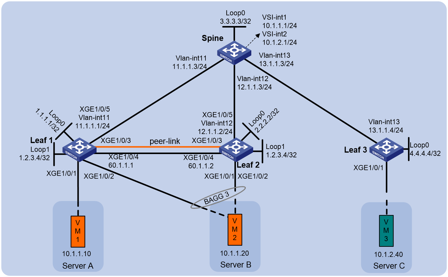
As shown in Figure 1:
· Leaf 1 and Leaf 2 form an M-LAG system, and they use an Ethernet aggregate link as the peer link.
· Server A is single-homed to Leaf 1, and Server B is connected to the M-LAG system through M-LAG interfaces.
· Leaf 1 and Leaf 2 are connected to the uplink device Spine through Equal-Cost Multi-Path (ECMP) routes.
· Spine is a centralized EVPN gateway connected to the Wide Area Network (WAN). It also serves as a route reflector (RR) and reflects routes between Leaf 1, Leaf 2, and Leaf 3.
Configure the network to meet the following requirements:
· Server A and Server B belong to VXLAN 10, and Server C belongs to VXLAN 20. Server A, Server B, and Server C communicate with each other through the centralized EVPN gateway.
· When a link fails between the two M-LAG member devices, Server A, Server B, and Server C can still communicate with each other.
|
Device |
Interface |
IP address |
Remarks |
|
Leaf 1 |
Loopback0 |
1.1.1.1/32 |
Router ID. |
|
Loopback1 |
1.2.3.4/32 |
Virtual VTEP address for the M-LAG system to establish VXLAN tunnels to remote devices. |
|
|
XGE 1/0/1 |
N/A |
Server A. Single-homed interface. |
|
|
XGE 1/0/2 |
N/A |
Server B. M-LAG member interface. |
|
|
XGE 1/0/3 |
N/A |
Leaf 2: XGE 1/0/3. Peer link member interface. |
|
|
XGE 1/0/4 |
60.1.1.1/24 |
Leaf 2: XGE 1/0/4. Keepalive interface. |
|
|
XGE 1/0/5 |
N/A |
Spine: XGE 1/0/5. |
|
|
Vlan-interface 11 |
11.1.1.1/24 |
VLAN interface connecting to Spine. |
|
|
Vlan-interface 2 |
40.94.1.1/24 |
Interface of the Layer 3 link connecting the two M-LAG member devices, which is used for forwarding east-west traffic or allowing north-south traffic to escape. |
|
|
Leaf 2 |
Loopback0 |
2.2.2.2/32 |
Router ID. |
|
Loopback1 |
1.2.3.4/32 |
Virtual VTEP address for the M-LAG system to establish VXLAN tunnels to remote devices. |
|
|
XGE 1/0/2 |
N/A |
Server B. M-LAG member interface. |
|
|
XGE 1/0/3 |
N/A |
Leaf 1: XGE 1/0/3. Peer link member interface. |
|
|
XGE 1/0/4 |
60.1.1.2/24 |
Leaf 1: XGE 1/0/4. Keepalive interface. |
|
|
XGE 1/0/5 |
N/A |
Spine: XGE 1/0/6. |
|
|
Vlan-interface 12 |
12.1.1.2/24 |
VLAN interface connecting to Spine. |
|
|
Vlan-interface 2 |
40.94.1.2/24 |
Interface of the Layer 3 link connecting the two M-LAG member devices, which is used for forwarding east-west traffic or allowing north-south traffic to escape. |
|
|
Leaf 3 |
Loopback0 |
4.4.4.4 |
Router ID. |
|
XGE 1/0/1 |
N/A |
Server C. |
|
|
XGE 1/0/5 |
N/A |
Spine: XGE 1/0/7. |
|
|
Vlan-interface 13 |
13.1.1.4/24 |
Spine. |
|
|
Spine |
Loopback0 |
3.3.3.3 |
Router ID. |
|
XGE 1/0/5 |
N/A |
Leaf 1: XGE 1/0/5. |
|
|
XGE 1/0/6 |
N/A |
Leaf 2: XGE 1/0/5. |
|
|
XGE 1/0/7 |
N/A |
Leaf 3: XGE 1/0/5. |
|
|
Vlan-interface 11 |
11.1.1.3/24 |
VLAN interface connecting to Leaf 1. |
|
|
Vlan-interface 12 |
12.1.1.3/24 |
VLAN interface connecting to Leaf 2. |
|
|
Vlan-interface 13 |
13.1.1.3/24 |
VLAN interface connecting to Leaf 3. |
|
|
VSI-interface 1 |
10.1.1.1/24 10::1/64 |
Gateway interface of VXLAN 10. |
|
|
VSI-interface 2 |
10.1.2.1/24 11::1/64 |
Gateway interface of VXLAN 20. |
Applicable product matrix
|
|
NOTE: In addition to running an applicable software version, you must also install the most recent patch, if any. |
|
Device |
Software version |
|
S10500, S10500X, S7600, S7600-X, S7600E-X, S7500X, S7500E |
R7625 and later |
|
S12500G-AF (type T cards) |
R7625 and later |
|
S12500G-AF (type S cards) |
R8054P04 and later |
|
S10500X-G, S7500X-G |
R7754P04 and later |
|
S5590XP-HI-G |
R7754P04 and later |
Analysis
· Leaf 1 and Leaf 2 act as M-LAG member devices, and an Ethernet aggregate link acts as the peer link.
· Leaf 1 and Leaf 2 are connected to the uplink device Spine through ECMP routes.
· Configure OSPF neighbors on the peer link between Leaf 1 and Leaf 2 to connect the single-homed services. The peer link also acts as a backup path for the network side and single-homed services.
· On the overlay, both IPv4 and IPv6 network settings exist.
Restrictions and guidelines
All devices in this example were started with the factory default configuration. When you are working on a live network, make sure you understand the potential impact of every command on your network.
The primary and secondary M-LAG member devices must deploy different uplink VLAN interfaces to avoid loops. As a best practice, disable the spanning tree protocol on the interfaces when making sure no physical loops exist.
On the primary and secondary M-LAG member devices, the frame match criteria of the dynamic ACs on the peer link must be the same.
· Solution 1: Use the l2vpn m-lag peer-link ac-match-rule vxlan-mapping command to enable the device to create frame match criteria based on VXLAN IDs for the dynamic ACs on the peer link.
If an M-LAG system uses an Ethernet aggregate link as the peer link, each member device creates a dynamic AC on the peer link when an AC (Ethernet service instance) is configured on a site-facing interface. The dynamic AC and the site-facing AC have the same frame match criteria and VSI mapping. If two site-facing ACs on different interfaces have the same frame match criteria but different VSI mappings, the dynamic ACs created for the site-facing ACs will conflict with each other on the peer link. Use this command to resolve the preceding issue.
· Solution 2: Create an AC on the peer link interface based on the frame match criteria of the site-facing Ethernet service instance.
You do not need to configure other settings. This solution is used by default.
Configuring IP addresses and unicast routing protocols
# On Server A and Server B, specify the gateway address as 10.1.1.1/10::1. On Server C, specify the gateway address as 10.1.2.1/11::1.
# Configure the IP address and subnet mask for each interface. (Details not shown.)
# Configure OSPF on the IP core network to advertise routes for subnets attached to the interfaces (including Loopback interfaces) on each node. Make sure the switches have connectivity to each other. As a best practice, execute the ospf peer hold-max-cost duration 300000 command on OSPF interfaces. (Details not shown.)
Configuring M-LAG member devices
Procedure summary
· Configuring the Layer 3 link connecting the M-LAG member devices
· Configuring the interconnect links between the M-LAG member devices and servers
Configuring M-LAG
|
Leaf 2 |
Description |
Remarks |
|
|
m-lag system-mac 1-1-1 |
m-lag system-mac 1-1-1 |
Configure the M-LAG system MAC address. |
You must assign the same M-LAG system MAC address to the member devices in an M-LAG system. |
|
m-lag system-number 1 |
m-lag system-number 2 |
Set the M-LAG system number. |
You must assign different M-LAG system numbers to the member devices in an M-LAG system. |
|
m-lag system-priority 10 |
m-lag system-priority 10 |
Set the M-LAG system priority. |
You must set the same M-LAG system priority on the member devices in an M-LAG system. |
|
drni restore-delay 300 |
drni restore-delay 300 |
Set the data restoration interval. |
This parameter specifies the maximum amount of time for the secondary M-LAG member device to synchronize data with the primary M-LAG member device during M-LAG system setup. |
|
m-lag standalone enable |
m-lag standalone enable |
(Optional.) Enable M-LAG standalone mode. |
Enable M-LAG standalone mode to avoid forwarding issues in the multi-active situation that might occur when the M-LAG system splits. Configure this feature before the M-LAG system splits. |
|
drni keepalive ip destination 60.1.1.2 source 60.1.1.1 |
drni keepalive ip destination 60.1.1.1 source 60.1.1.2 |
Configure the destination and source IPv4 addresses of keepalive packets. |
N/A |
|
interface Ten-gigabitethernet1/0/4 |
interface Ten-gigabitethernet1/0/4 |
Keepalive interface. |
N/A |
|
port link-mode route |
port link-mode route |
Configure the keepalive interface to operate in route mode as a Layer 3 interface. |
N/A |
|
ip address 60.1.1.1 24 |
ip address 60.1.1.2 24 |
Configure the source IPv4 address of keepalive packets. |
N/A |
|
quit |
quit |
Return to system view. |
N/A |
|
m-lag mad exclude interface Ten-gigabitethernet1/0/4 |
m-lag mad exclude interface Ten-gigabitethernet1/0/4 |
Exclude the keepalive interface from the shutdown action by M-LAG MAD. |
N/A |
|
interface bridge-aggregation 1 |
interface bridge-aggregation 1 |
Create an Ethernet aggregate interface. |
The interface is used as the peer link interface. |
|
link-aggregation mode dynamic |
link-aggregation mode dynamic |
Configure the aggregate interface of the peer link to operate in dynamic mode. |
N/A |
|
quit |
quit |
Return to system view. |
N/A |
|
interface range Ten-gigabitethernet 1/0/3 |
interface range Ten-gigabitethernet 1/0/3 |
Enter the view of the physical interface for the peer link. |
N/A |
|
port link-aggregation group 1 |
port link-aggregation group 1 |
Assign the physical interface for the peer link to the peer link aggregation group. |
N/A |
|
quit |
quit |
Return to system view. |
N/A |
|
interface bridge-aggregation 1 |
interface bridge-aggregation 1 |
Enter Ethernet aggregate interface view. |
N/A |
|
port m-lag peer-link 1 |
port m-lag peer-link 1 |
Configure Bridge-Aggregation 1 as the peer link interface. |
N/A |
|
port trunk pvid vlan 4094 |
port trunk pvid vlan 4094 |
Set the PVID of the trunk port to VLAN 4094. |
N/A |
|
undo mac-address static source-check enable |
undo mac-address static source-check enable |
Disable source MAC check on the interface to avoid interruption of traffic forwarded at Layer 3 across the peer link. |
N/A |
|
quit |
quit |
Return to system view. |
N/A |
Configuring the Layer 3 link connecting the M-LAG member devices
|
Leaf 1 |
Leaf 2 |
Description |
Remarks |
|
vlan 2 |
vlan 2 |
Create VLAN 2. |
N/A |
|
quit |
quit |
Return to system view. |
N/A |
|
interface vlan-interface 2 |
interface vlan-interface 2 |
Create VLAN-interface 2. |
Interface of the Layer 3 link connecting the two M-LAG member devices, which is used for forwarding east-west traffic or allowing north-south traffic to escape. |
|
ip address 40.94.1.1 255.255.255.0 |
ip address 40.94.1.2 255.255.255.0 |
Assign an IPv4 address to VLAN-interface 2. |
N/A |
|
ospf 1 area 0.0.0.0 |
ospf 1 area 0.0.0.0 |
Enable OSPF on the interface. |
N/A |
|
quit |
quit |
Return to system view. |
N/A |
|
drni mad exclude interface Vlan-interface 2 |
drni mad exclude interface Vlan-interface 2 |
Exclude the VLAN interface from the shutdown action by M-LAG MAD. |
N/A |
Configuring the interconnect links between the M-LAG member devices and servers
|
Leaf 1 |
Leaf 2 |
Description |
Remarks |
|
l2vpn enable |
l2vpn enable |
Enable L2VPN. |
N/A |
|
evpn m-lag local 1.1.1.1 remote 2.2.2.2 |
evpn m-lag local 2.2.2.2 remote 1.1.1.1 |
Specify the IP addresses of the local and peer VTEPs in an M-LAG system. |
This step is required if the M-LAG system uses an Ethernet aggregate link as the peer link and has an AC attached to only one of the member devices. |
|
evpn drni group 1.2.3.4 |
evpn drni group 1.2.3.4 |
Enable EVPN distributed relay and set the virtual VTEP address. |
N/A |
|
vsi vpna |
vsi vpna |
Create VSI instance vpna. |
N/A |
|
vxlan 10 |
vxlan 10 |
Configure VXLAN 10. |
N/A |
|
arp suppression enable |
arp suppression enable |
Configure ARP suppression. |
N/A |
|
evpn encapsulation vxlan |
evpn encapsulation vxlan |
Create an EVPN instance. |
N/A |
|
route-distinguisher auto |
route-distinguisher auto |
Configure the device to automatically generate an RD for the EVPN instance. |
N/A |
|
vpn-target auto |
vpn-target auto |
Configure the device to automatically generate an RT for the EVPN instance. |
N/A |
|
quit |
quit |
Return to VSI view. |
N/A |
|
quit |
quit |
Return to system view. |
N/A |
|
bgp 200 |
bgp 200 |
Enter BGP view. |
N/A |
|
peer 3.3.3.3 as-number 200 |
peer 3.3.3.3 as-number 200 |
Configure a BGP peer. |
N/A |
|
peer 3.3.3.3 connect-interface loopback 0 |
peer 3.3.3.3 connect-interface loopback 0 |
Specify a source interface for establishing TCP connections to a BGP peer. |
N/A |
|
address-family l2vpn evpn |
address-family l2vpn evpn |
Configure BGP to advertise EVPN routes. |
N/A |
|
peer 3.3.3.3 enable |
peer 3.3.3.3 enable |
Enable a BGP EVPN peer. |
N/A |
|
quit |
quit |
Return to BGP view. |
N/A |
|
quit |
quit |
Return to system view. |
N/A |
|
interface Ten-gigabitethernet 1/0/2 |
N/A |
Single-homed interface. |
N/A |
|
service-instance 1000 |
N/A |
Create Ethernet service instance 1000 on the interface connecting to the server. |
N/A |
|
encapsulation s-vid 2 |
N/A |
Configure the instance to match data frames of VLAN 2. |
N/A |
|
xconnect vsi vpna |
N/A |
Map Ethernet service instance 1000 to VSI vpna. |
N/A |
|
quit |
N/A |
Return to system view. |
N/A |
|
interface bridge-aggregation 3 |
interface bridge-aggregation 3 |
Enter Ethernet aggregate interface view. |
N/A |
|
service-instance 1000 |
service-instance 1000 |
Create Ethernet service instance 1000 on the interface connecting to the server. |
N/A |
|
encapsulation s-vid 3 |
encapsulation s-vid 3 |
Configure the instance to match data frames of VLAN 3. |
N/A |
|
xconnect vsi vpna |
xconnect vsi vpna |
Map Ethernet service instance 1000 to VSI vpna. |
N/A |
|
quit |
quit |
Return to system view. |
N/A |
|
m-lag mad exclude interface loopback 0 |
m-lag mad exclude interface loopback 0 |
Exclude all VXLAN interfaces from the shutdown action by M-LAG MAD. |
N/A |
|
m-lag mad exclude interface vlan-interface 11 |
m-lag mad exclude interface vlan-interface 12 |
Exclude all VXLAN interfaces from the shutdown action by M-LAG MAD. |
N/A |
Configuring the uplink device Leaf 3
Procedure summary
Configuring EVPN VXLAN
|
Leaf 3 |
Description |
Remarks |
|
l2vpn enable |
Enable L2VPN. |
N/A |
|
vsi vpnb |
Create VSI instance vpnb. |
N/A |
|
vxlan 20 |
Create VXLAN 20. |
N/A |
|
evpn encapsulation vxlan |
Create an EVPN instance in VSI instance vpnb. |
N/A |
|
route-distinguisher auto |
Configure the device to automatically generate an RD for the EVPN instance. |
N/A |
|
vpn-target auto |
Configure the device to automatically generate an RT for the EVPN instance. |
N/A |
|
quit |
Return to VSI view. |
N/A |
|
quit |
Return to system view. |
N/A |
|
bgp 200 |
Enter BGP view. |
N/A |
|
peer 3.3.3.3 as-number 200 |
Configure a BGP peer. |
N/A |
|
peer 3.3.3.3 connect-interface loopback 0 |
Specify a source interface for establishing TCP connections to a BGP peer. |
N/A |
|
address-family l2vpn evpn |
Enter L2VPN EVPN view. |
N/A |
|
peer 3.3.3.3 enable |
Enable a BGP EVPN peer. |
N/A |
|
quit |
Return to BGP view. |
N/A |
|
quit |
Return to system view. |
N/A |
|
interface Ten-gigabitethernet1/0/3 |
Enter Ethernet interface view. |
N/A |
|
service-instance 1000 |
Create Ethernet service instance 1000 on the interface connecting to the server. |
N/A |
|
encapsulation s-vid 4 |
Configure the instance to match data frames of VLAN 4. |
N/A |
|
xconnect vsi vpnb |
Map Ethernet service instance 1000 to VSI vpnb. |
N/A |
|
quit |
Return to system view. |
N/A |
Configuring the gateway device Spine
Procedure summary
Configuring EVPN VXLAN
|
Spine |
Description |
Remarks |
|
l2vpn enable |
Enable L2VPN. |
N/A |
|
vxlan tunnel mac-learning disable |
Disable remote MAC address learning for VXLANs. This setting avoids the conflict between automatically learned MAC address entries and MAC address entries advertised through BGP EVPN. |
N/A |
|
vsi vpna |
Create VSI instance vpna. |
N/A |
|
vxlan 10 |
Configure VXLAN 10. |
N/A |
|
evpn encapsulation vxlan |
Create an EVPN instance. |
N/A |
|
route-distinguisher auto |
Configure the device to automatically generate an RD for the EVPN instance. |
N/A |
|
vpn-target auto |
Configure the device to automatically generate an RT for the EVPN instance. |
N/A |
|
quit |
Return to VSI view. |
N/A |
|
quit |
Return to system view. |
N/A |
|
vsi vpnb |
Create VSI instance vpnb. |
N/A |
|
vxlan 20 |
Configure VXLAN 20. |
N/A |
|
evpn encapsulation vxlan |
Create an EVPN instance. |
N/A |
|
route-distinguisher auto |
Configure the device to automatically generate an RD for the EVPN instance. |
N/A |
|
vpn-target auto |
Configure the device to automatically generate an RT for the EVPN instance. |
N/A |
|
quit |
Return to VSI view. |
N/A |
|
quit |
Return to system view. |
N/A |
|
bgp 200 |
Enter BGP view. |
N/A |
|
group evpn |
Configure a BGP EVPN group |
N/A |
|
peer 1.1.1.1 group evpn |
Configure a BGP peer. |
N/A |
|
peer 2.2.2.2 group evpn |
Configure a BGP peer. |
N/A |
|
peer 4.4.4.4 group evpn |
Configure a BGP peer. |
N/A |
|
peer evpn as-number 200 |
Configure an AS number for the BGP EVPN group |
N/A |
|
peer evpn connect-interface loopback 0 |
Specify a source interface for establishing TCP connections to a BGP EVPN group. |
N/A |
|
address-family l2vpn evpn |
Enter L2VPN EVPN view. |
N/A |
|
peer evpn enable |
Enable the BGP EVPN group. |
N/A |
|
undo policy vpn-target |
Disable route target filtering for BGP EVPN routes. |
N/A |
|
peer evpn reflect-client |
Configure BGP to reflect EVPN routes. |
N/A |
|
quit |
Return to BGP view. |
N/A |
|
quit |
Return to system view. |
N/A |
|
interface vsi-interface 1 |
Create VSI-interface 1. |
N/A |
|
ip address 10.1.1.1 255.255.255.0 |
Configure an IP address, which is to be used as the gateway address of the servers in VXLAN 10. |
N/A |
|
Ipv6 address 10::1 64 |
Configure an IPv6 address, which is to be used as the gateway address of the servers in VXLAN 10. |
N/A |
|
quit |
Return to system view. |
N/A |
|
interface vsi-interface 2 |
Create VSI-interface 2. |
N/A |
|
ip address 10.1.2.1 255.255.255.0 |
Configure an IP address, which is to be used as the gateway address of the servers in VXLAN 20. |
N/A |
|
Ipv6 address 11::1 64 |
Configure an IPv6 address, which is to be used as the gateway address of the servers in VXLAN 20. |
N/A |
|
quit |
Return to system view. |
N/A |
|
vsi vpna |
Enter VSI view. |
N/A |
|
gateway vsi-interface 1 |
Specify VSI-interface 1 as the gateway interface for the VSI of VXLAN 10. |
N/A |
|
quit |
Return to system view. |
N/A |
|
vsi vpnb |
Enter VSI view. |
N/A |
|
gateway vsi-interface 2 |
Specify VSI-interface 2 as the gateway interface for the VSI of VXLAN 20. |
N/A |
|
quit |
Return to system view. |
N/A |
Traffic model
About the traffic model
The traffic model contains the following information:
· ID—Traffic ID, in O-X-XXX format. The first segment (O) represents overlay traffic. The second segment (X) represents the IP version (4 for IPv4 and 6 for IPv6). The third segment (XXX) represents a unique number for the traffic.
· Type—Traffic type, such as known unicast/IPv4 and unicast/L2.
· Direction—Traffic direction, such as inter-leaf east-west traffic and north-south traffic.
· Path—The nodes that the traffic traverses from the source to the destination.
· Simulation method—Traffic simulation method. Testers are used to simulate the patterns of traffic on the network set up in this example.
· Simulation traffic load—The network can be tested under light load (fewer than 1000 simulation traffic flows) or heavy load (more than 1000 simulation traffic flows).
· Traffic direction to firewalls/LBs—No firewalls or LBs are used in this example, or traffic is directed to firewalls or LBs through PBR, M-LAG+VRRP, or static routing.
Overlay traffic
|
ID |
Type |
Direction |
Path |
Simulation method |
Simulation traffic load |
Traffic direction to firewalls/LBs |
Remarks |
|
O-4-001 |
Known unicast/IPv4 |
Inter-leaf east-west traffic |
Server A-Leaf 1-Spine-Leaf 3-Server C |
Tester |
Light |
N/A |
When the uplink interface fails, traffic is forwarded along the Layer 3 link between M-LAG member devices |
|
O-4-002 |
Known unicast/IPv4 |
Inter-leaf east-west traffic |
Server B-Leaf 1/2-Spine-Leaf 3-Server C |
Tester |
Light |
N/A |
N/A |
|
O-6-001 |
Known unicast/IPv6 |
Inter-leaf east-west traffic |
ServerA-Leaf 1-Spine-Leaf 3-Server C |
Tester |
Light |
N/A |
When the uplink interface fails, traffic is forwarded along the Layer 3 link between M-LAG member devices |
|
O-6-002 |
Known unicast/IPv6 |
Inter-leaf east-west traffic |
Server B-Leaf 1/2-Spine-Leaf 3-Server C |
Tester |
Light |
N/A |
N/A |
Convergence performance test results
Failure test results
Table 1 Link failure test results
|
Device |
Failure cause |
Traffic downtime |
Remarks |
|
Leaf1 |
Single member link failure in an M-LAG interface |
≤ 100 ms |
N/A |
|
Recovery from a single M-LAG interface member link failure |
≤ 100 ms |
N/A |
|
|
Single uplink failure |
≤ 500 ms |
N/A |
|
|
Recovery from a single uplink failure |
≤ 200 ms |
N/A |
|
|
Complete peer link failure |
≤ 500 ms |
Focus on M-LAG interface services. Single-homed interface services are not assured. |
|
|
Recovery from a complete peer link failure |
≤ 100 ms |
Focus on M-LAG interface services. Single-homed interface services can recover. |
|
|
Keepalive interface failure |
0 ms |
N/A |
|
|
Recovery from a keepalive interface failure |
0 ms |
N/A |
|
|
Keepalive link and peer link failure |
≤ 500 ms |
Focus on M-LAG interface services. Single-homed interface services are not assured. |
|
|
Recovery from a keepalive link and peer link failure |
≤ 200 ms |
Focus on M-LAG interface services. Single-homed interface services can recover. |
|
|
Restart of one M-LAG member device |
≤ 500 ms |
Focus on M-LAG interface services. Single-homed interface services are not assured. |
|
|
Recovery from M-LAG member device restart |
≤ 200 ms |
Focus on M-LAG interface services. Single-homed interface services can recover. |
|
|
Switching fabric module failure |
≤ 100 ms |
N/A |
|
|
Recovery from a switching fabric module failure |
≤ 100 ms |
N/A |
Verifying the configuration
Verification commands
|
DeviceA |
DeviceB |
Description |
|
display interface tunnel |
display interface tunnel |
Displays tunnel interface information. |
|
display l2vpn vsi |
display l2vpn vsi |
Displays VSI information. |
|
display bgp l2vpn evpn |
display bgp l2vpn evpn |
Displays BGP EVPN routes. |
Procedure
1. Verify the configuration on the EVPN gateway device Spine.
# Display the EVPN route information on Spine to verify that Spine has sent the MAC/IP routes and Inclusive Multicast Ethernet Tag (IMET) routes of the gateway and received the MAC/IP routes and IMET routes from Leaf 1, Leaf 2, and Leaf 3.
[Spine] display bgp l2vpn evpn
BGP local router ID is 3.3.3.3
Status codes: * - valid, > - best, d - dampened, h - history,
s - suppressed, S - stale, i - internal, e - external
a - additional-path
Origin: i - IGP, e - EGP, ? - incomplete
Total number of routes from all PEs: 5
Route distinguisher: 1:100
Total number of routes: 5
* > Network : [2][0][48][0800-2700-400e][0][0.0.0.0]/104
NextHop : 0.0.0.0 LocPrf : 100
PrefVal : 32768 OutLabel : NULL
MED : 0
Path/Ogn: i
* i Network : [2][0][48][0800-2700-400e][0][0.0.0.0]/104
NextHop : 1.2.3.4 LocPrf : 100
PrefVal : 0 OutLabel : NULL
MED : 0
Path/Ogn: i
* >i Network : [3][0][32][1.2.3.4]/80
NextHop : 1.2.3.4 LocPrf : 100
PrefVal : 0 OutLabel : NULL
MED : 0
Path/Ogn: i
* >i Network : [3][0][32][3.3.3.3]/80
NextHop : 0.0.0.0 LocPrf : 100
PrefVal : 0 OutLabel : NULL
MED : 0
Path/Ogn: i
* >i Network : [3][0][32][2.2.2.2]/80
NextHop : 1.2.3.4 LocPrf : 100
PrefVal : 0 OutLabel : NULL
MED : 0
Path/Ogn: i
# On Spine, display tunnel interface information to verify that the VXLAN tunnels are up. The destination addresses of tunnels are virtual VTEP addresses.
[Spine] display interface tunnel
Tunnel0
Current state: UP
Line protocol state: UP
Description: Tunnel0 Interface
Bandwidth: 64 kbps
Maximum transmission unit: 1464
Internet protocol processing: Disabled
Output queue - Urgent queuing: Size/Length/Discards 0/100/0
Output queue - Protocol queuing: Size/Length/Discards 0/500/0
Output queue - FIFO queuing: Size/Length/Discards 0/75/0
Last clearing of counters: Never
Tunnel source 3.3.3.3, destination 1.2.3.4
Tunnel protocol/transport UDP_VXLAN/IP
Last 300 seconds input rate: 0 bytes/sec, 0 bits/sec, 0 packets/sec
Last 300 seconds output rate: 0 bytes/sec, 0 bits/sec, 0 packets/sec
Input: 0 packets, 0 bytes, 0 drops
Output: 0 packets, 0 bytes, 0 drops
# On Spine, display VSI information to view the VXLANs created in VSIs, VXLAN tunnels associated with VXLANs, and VSI interfaces associated with VSIs.
[Spine] display l2vpn vsi verbose
VSI Name: vpna
VSI Index : 0
VSI State : Up
MTU : 1500
Bandwidth : Unlimited
Broadcast Restrain : Unlimited
Multicast Restrain : Unlimited
Unknown Unicast Restrain: Unlimited
MAC Learning : Enabled
MAC Table Limit : -
MAC Learning rate : -
Drop Unknown : -
Flooding : Enabled
Statistics : Disabled
Gateway Interface : VSI-interface 1
VXLAN ID : 10
Tunnels:
Tunnel Name Link ID State Type Flood proxy
Tunnel0 0x5000000 UP Auto Disabled
VSI Name: vpnb
VSI Index : 1
VSI State : Up
MTU : 1500
Bandwidth : Unlimited
Broadcast Restrain : Unlimited
Multicast Restrain : Unlimited
Unknown Unicast Restrain: Unlimited
MAC Learning : Enabled
MAC Table Limit : -
MAC Learning rate : -
Drop Unknown : -
Flooding : Enabled
Statistics : Disabled
Gateway Interface : VSI-interface 2
VXLAN ID : 20
Tunnels:
Tunnel Name Link ID State Type Flood proxy
Tunnel1 0x5000001 UP Auto Disabled
2. Verify the M-LAG system configuration.
# Verify EVPN routing information on node Leaf 1.
[Leaf 1] display bgp l2vpn evpn
BGP local router ID is 1.2.3.4
Status codes: * - valid, > - best, d - dampened, h - history,
s - suppressed, S - stale, i - internal, e - external
a - additional-path
Origin: i - IGP, e - EGP, ? - incomplete
Total number of routes from all PEs: 5
Route distinguisher: 1:100
Total number of routes: 5
* > Network : [2][0][48][0800-2700-400e][0][0.0.0.0]/104
NextHop : 1.2.3.4 LocPrf : 100
PrefVal : 32768 OutLabel : NULL
MED : 0
Path/Ogn: i
* >i Network : [2][0][48][46b2-aea0-0101][0][0.0.0.0]/104
NextHop : 3.3.3.3 LocPrf : 100
PrefVal : 0 OutLabel : NULL
MED : 0
Path/Ogn: i
* > Network : [2][0][48][ac1e-24e3-0201][0][0.0.0.0]/104
NextHop : 3.3.3.3 LocPrf : 100
PrefVal : 0 OutLabel : NULL
MED : 0
Path/Ogn: i
* >i Network : [3][0][32][1.2.3.4]/80
NextHop : 1.2.3.4 LocPrf : 100
PrefVal : 32768 OutLabel : NULL
MED : 0
Path/Ogn: i
* >i Network : [3][0][32][3.3.3.3]/80
NextHop : 3.3.3.3 LocPrf : 100
PrefVal : 0 OutLabel : NULL
MED : 0
Path/Ogn: i
[Leaf 1] display interface tunnel
Tunnel0
Current state: UP
Line protocol state: UP
Description: Tunnel0 Interface
Bandwidth: 64 kbps
Maximum transmission unit: 1464
Internet protocol processing: Disabled
Output queue - Urgent queuing: Size/Length/Discards 0/100/0
Output queue - Protocol queuing: Size/Length/Discards 0/500/0
Output queue - FIFO queuing: Size/Length/Discards 0/75/0
Last clearing of counters: Never
Tunnel source 1.2.3.4, destination 3.3.3.3
Tunnel protocol/transport UDP_VXLAN/IP
Last 300 seconds input rate: 0 bytes/sec, 0 bits/sec, 0 packets/sec
Last 300 seconds output rate: 0 bytes/sec, 0 bits/sec, 0 packets/sec
Input: 0 packets, 0 bytes, 0 drops
Output: 0 packets, 0 bytes, 0 drops
# View the VSI information on Leaf 1 to verify that ACs are automatically created on the peer link and they are associated with VSIs.
[Leaf 1] display l2vpn vsi verbose
VSI Name: vpna
VSI Index : 1
VSI State : Up
MTU : 1500
Bandwidth : Unlimited
Broadcast Restrain : Unlimited
Multicast Restrain : Unlimited
Unknown Unicast Restrain: Unlimited
MAC Learning : Enabled
MAC Table Limit : -
MAC Learning rate : -
Drop Unknown : -
Flooding : Enabled
Statistics : Disabled
VXLAN ID : 10
Tunnels:
Tunnel Name Link ID State Type Flood proxy
Tunnel0 0x5000000 UP Auto Disabled
ACs:
AC Link ID State Type
XGE1/0/1 srv1000 0 Up Manual
BAGG1 srv2 1 Up Dynamic (M-LAG)
BAGG3 srv1000 2 Up Manual
3. Verify that Server A/Server B can communicate with Server C.
4. Verify that traffic can still be forwarded between Server B and Server C when the downlink M-LAG member interface of Leaf 1 or Leaf 2 fails.
Transient packet loss might occur during the switchover process.
5. Verify that traffic can still be forwarded between Server A/Server B and Server C when the uplink interface of Leaf 1 or Leaf 2 fails.
Transient packet loss might occur during the switchover process.
Upgrade procedure
Pre-upgrade verification commands
Before you perform an upgrade, use the commands in “Verifying the configuration” and the commands in the following table to verify that all requirements are met for an upgrade.
Table 3 Pre-upgrade verification commands
|
Leaf 1 |
Leaf 2 |
Description |
|
display device |
display device |
Displays summary information about the peer link interfaces and M-LAG interfaces in the M-LAG system. |
|
display boot-loader |
display boot-loader |
Displays the current software images and startup software images. |
|
display version |
display version |
Displays system version information. |
Upgrade procedure
To upgrade software:
1. Execute the display version command to verify the current BootWare image version and startup software version.
2. Use the release notes for the upgrade software version to evaluate the upgrade impact on your network and verify the following items:
¡ Software and hardware compatibility.
¡ Version and size of the upgrade software.
¡ Compatibility of the upgrade software with the current BootWare image and startup software image.
3. Use the release notes to verify whether the upgrade software images require a license. If licenses are required, check the system for availability of valid licenses. If no valid licenses are available, register and activate licenses for each license-based software image.
4. Use the dir command to verify that the device has sufficient storage space for the upgrade images. If the storage space is not sufficient, delete unused files by using the delete command. Make sure all MPUs in the system have sufficient storage space.
5. After Leaf 1 and Leaf 2 form an M-LAG system, perform the following tasks:
a. Check the LLDP neighbors of Leaf 1 to obtain the LLDP state information of all interfaces on Leaf 1.
b. Manually shut down all interfaces connecting to the other devices (except M-LAG peer link interfaces and keepalive interfaces) on Leaf 1 to switch all incoming and outgoing traffic of Leaf 1 to Leaf 2.
6. Save the configuration on Leaf 1, and use FTP or TFTP to transfer the upgrade image file to the root directory of a file system. Upgrade Leaf 1 and reboot it.
7. When Leaf 1 is being rebooted, manually shut down the interfaces connecting Leaf 2 to Leaf 1. The interfaces are typically peer link interfaces and keepalive interfaces.
8. After Leaf 1 is rebooted, bring up the interfaces that have been shut down on Leaf 2. Wait for M-LAG to restore between Leaf 1 and Leaf 2.
9. After Leaf 1 and Leaf 2 form an M-LAG system again, bring up the interfaces connecting to other devices. Wait for the traffic to restore.
For more information about upgrading software on an M-LAG system, see H3C Switches M-LAG System Upgrade Guide.
Upgrade the software. For more information about the software upgrade procedure, see the fundamentals configuration guide for the device.
Estimated upgrade downtime
See “Convergence performance test results.” The upgrade downtime of each device contains the traffic downtime for restart of one M-LAG member device and recovery from M-LAG member device restart.
Post-upgrade verification commands
After the upgrade finishes, use the commands in “Verifying the configuration” and the commands in the following table to verify that the upgrade has been done correctly.
Table 4 Post-upgrade verification commands
|
Leaf 1 |
Leaf 2 |
Description |
|
display device |
display device |
Displays summary information about the peer link interfaces and M-LAG interfaces in the M-LAG system. |
|
display boot-loader |
display boot-loader |
Displays the current software images and startup software images. |
|
display version |
display version |
Displays system version information. |
Node expansion
Pre-expansion verification commands
Before you perform a node expansion, use the commands in “Verifying the configuration” and the commands in the following table to verify that all requirements are met for an expansion.
Table 5 Pre-expansion verification commands
|
Leaf 1 |
Leaf 2 |
Description |
|
display device |
display device |
Displays summary information about the peer link interfaces and M-LAG interfaces in the M-LAG system. |
|
display boot-loader |
display boot-loader |
Displays the current software images and startup software images. |
|
display version |
display version |
Displays system version information. |
Node expansion
1. Make sure the expansion device is not connected to the management network.
2. Upgrade the device to the target software version.
3. Configure the device.
4. Connect the device to the management network.
Estimated expansion downtime
N/A
Post-expansion verification commands
After the expansion finishes, use the commands in the following table to verify that the expansion has been done correctly.
Table 6 Post-expansion verification commands
|
Leaf 1 |
Leaf 2 |
Description |
|
display device |
display device |
Displays summary information about the peer link interfaces and M-LAG interfaces in the M-LAG system. |
|
display boot-loader |
display boot-loader |
Displays the current software images and startup software images. |
|
display version |
display version |
Displays system version information. |
Replacement procedure
Service module replacement
Pre-replacement verification commands
Execute the commands in “Verifying the configuration” and the following commands to verify that all requirements are met for a replacement.
Table 7 Pre-replacement verification commands
|
Leaf 1 |
Leaf 2 |
Description |
|
display device |
display device |
Displays device information. |
|
display boot-loader |
display boot-loader |
Displays the current software images and startup software images. |
|
display version |
display version |
Displays system version information. |
Replacement procedure
Before you replace an interface module, make sure the service and management traffic has switched over to other interface modules that are operating correctly.
Replace the interface modules online while the system is operating or power off the system before you do the replacement, depending on the evaluation of the conditions.
Estimated replacement downtime
See “Convergence performance test results.” The replacement downtime of each interface module contains the traffic downtime for single member link failure in an M-LAG interface, single uplink failure, recovery from a single member link failure in an M-LAG interface, and recovery from a single uplink failure.
Post-replacement verification commands
Use the same commands for pre-replacement verification to verify that the system can operate correctly after the hardware replacement.
Switching fabric module replacement
Pre-replacement verification commands
Execute the commands in “Verifying the configuration” and the following commands to verify that all requirements are met for a replacement.
Table 8 Pre-replacement verification commands
|
Leaf 1 |
Leaf 2 |
Description |
|
display device |
display device |
Displays summary information about the peer link interfaces and M-LAG interfaces in the M-LAG system. |
|
display boot-loader |
display boot-loader |
Displays the current software images and startup software images. |
|
display version |
display version |
Displays system version information. |
Replacement procedure
Replace the switching fabric module online while the system is operating or power off the system before you do the replacement, depending on the evaluation of the conditions.
Estimated replacement downtime
See “Convergence performance test results.” The replacement downtime of each switching fabric module contains the traffic downtime for switching fabric module failure and recovery from a switching fabric module failure.
Post-replacement verification commands
Use the same commands for pre-replacement verification to verify that the system can operate correctly after the hardware replacement.
