- Table of Contents
-
- H3C HDM Configuration Examples-6W100
- 01-H3C Redfish Configuration Examples
- 02-H3C LDAP Configuration Examples
- 03-H3C IPMI Configuration Examples
- 04-H3C SNMP Configuration Examples
- 05-H3C HDM Mobile Configuration Examples for Remote Access to a Server Through L2TP VPN
- 06-H3C HDM Configuration Examples for Obtaining Event Logs Through the Redfish Interface
- 07-H3C HDM SMTP Configuration Examples
- 08-H3C HDM Zabbix-Based Server Monitoring Configuration Examples
- 09-H3C HDM Network Settings Configuration Examples
- 10-H3C hREST Configuration Examples for Configuring SNMP and Obtaining the CPU Information
- 11-H3C HDM Configuration Management Configuration Examples
- 12-HDM AD Configuration Examples
- 13-H3C HDM SOL Configuration Examples
- 14-HDM Unified Control Configuration Examples
- Related Documents
-
| Title | Size | Download |
|---|---|---|
| 10-H3C hREST Configuration Examples for Configuring SNMP and Obtaining the CPU Information | 382.19 KB |
H3C hREST
Configuration Examples for Configuring SNMP and Obtaining the CPU Information
Copyright © 2023 New H3C Technologies Co., Ltd. All rights reserved.
No part of this manual may be reproduced or transmitted in any form or by any means without prior written consent of New H3C Technologies Co., Ltd.
Except for the trademarks of New H3C Technologies Co., Ltd., any trademarks that may be mentioned in this document are the property of their respective owners.
The information in this document is subject to change without notice.
Example: Configuring SNMP through hREST commands
Example: Obtaining CPU information through hREST commands
Introduction
hREST is a command line tool developed based on the HDM interface and is convenient for users to manage servers. Users can manage servers by querying and configuring commands on hREST. This document describes configuration examples of configuring SNMP and obtaining CPU information through the hREST command line tool.
Prerequisites
Procedures and information in the examples might be slightly different depending on the software or hardware version of the products.
The configuration was created and verified in a lab environment, and all the servers and software were started with the factory default configuration. When you are working on a live network, make sure you understand the potential impact of every command on your network.
The following information is provided based on the assumption that you have basic knowledge of of hREST.
Applicable scenarios
This document is applicable to scenarios where you need to configure SNMP with the hREST tool to quickly obtain HDM information, which can efficiently obtain device information in real time, so as to respond to and deal with server issues in a timely manner.
Configuration example
Network requirement
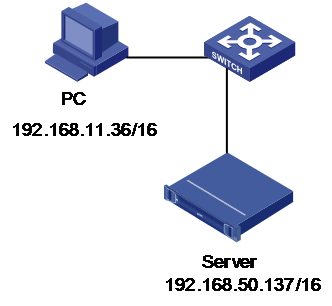
As shown in Figure 1, HDM of the H3C UniServer R4900 G3 server is connected to the PC through the dedicated HDM network port, and the network is accessible. Now the requirement is to remotely manage servers through the command line of hREST on the PC, including configuring SNMP and obtaining CPU information. The network diagram is as follows:
· HDM management software information:
¡ IP addresses: 192.168.50.137/16
¡ Administrator account: admin
¡ Administrator password: Password@_
· PC information:
¡ IP addresses: 192.168.11.35/16
¡ The PC is installed with a Windows system and the hREST command line tool.
Figure 1 hREST network diagram
Key steps
Use the hREST tool and see the description of related commands in the hREST user guide to perform related operations.
The basic analysis is:
1. Query the current status of devices.
2. Confirm the configuration parameters and send commands to modify the configuration.
3. Send the query command again to confirm that the modification succeeded.
Software versions used
This example was created and verified on HDM-2.96 and hREST-1.15P02.
Example: Configuring SNMP through hREST commands
Procedures
Obtaining the current SNMP settings
1. Open the folder directory D:hREST_Windows_V1.15P02 where the hREST installation package resides. Enter the bin directory, press Shift while right-clicking in the blank, and select Open command window here to open the Windows CMD.
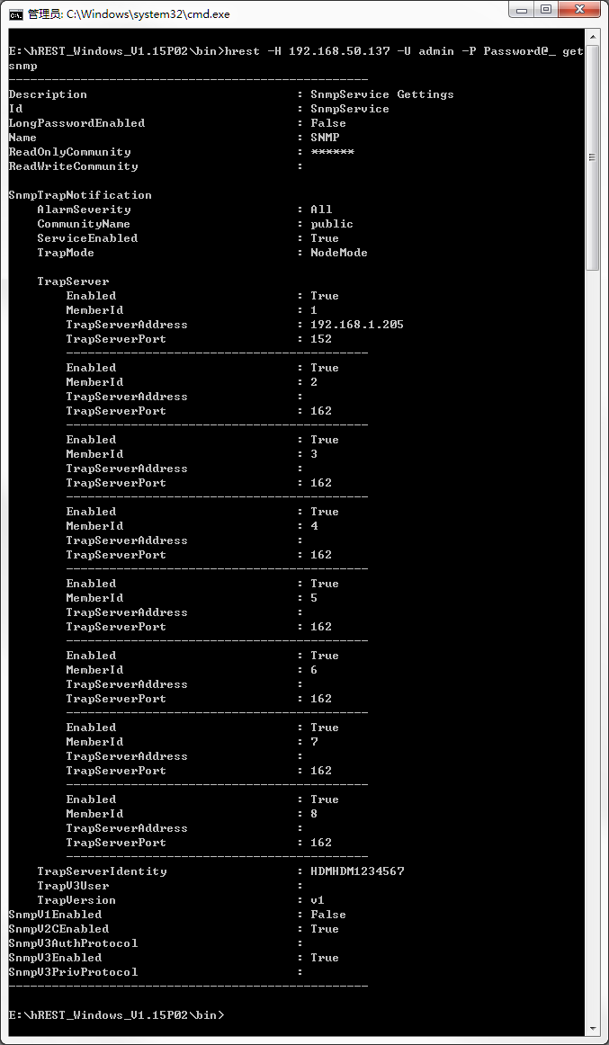
2. Execute the following command in the Windows CMD interface to obtain the current SNMP information, as shown in Figure 2.
hrest –H 192.168.50.137 –U admin –P Password@_ getsnmp
|
|
NOTE: The common format of hREST commands is hrest -H hostname -U username -P password <command>. · -H hostname—Specifies the IP address of the device to be managed. · -U username—Specifies the HDM username of the device to be managed. · -P password—Specifies the HDM password of the device to be managed. · <command>: The specific action performed by the hREST command. |
Figure 2 Obtaining the current SNMP information
Configuring SNMP
1. Execute the following command to enable SNMP V1, as shown in Figure 3. If SNMP v3 is enabled by default, you do not need to configure it.
hREST -H 192.168.50.137 -U admin -P Password@_ setsnmp -V1E Enable

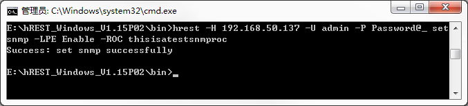
2. Execute the following command to enable the long community string feature and configure the read-only community string with a string of 16 to 32 characters, as shown in Figure 4.
hREST -H 192.168.50.137 -U admin -P Password@_ setsnmp –LPE Enable –ROC thisisatestsnmproc
|
|
NOTE: If the long community string feature is disabled, the read-only community string needs to be configured with a string of 1 to 32 characters. The read-only community string and the read/write community string must be different. The configuration configured through the hREST tool and the configuration on the HDM Web page must be the same. To ensure successful configuration, you need to consider the factors of the associated items. |
Figure 4 Configuring the long community string feature status
Configure SNMP trap settings
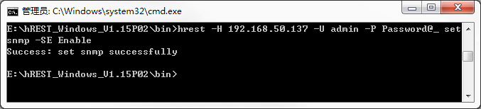
1. Execute the following command to enable SNMP trap packet notification, as shown in Figure 5.
hREST -H 192.168.50.137 -U admin -P Password@_ setsnmp –SE Enable
Figure 5 Enabling SNMP trap packet notification
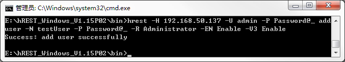
2. Execute the following command to add the user named testUser who supports SNMP extended privileges, as shown in Figure 6.
hrest –H 192.168.10.6 –U ****** -P ****** adduser -N testUser -P Password@_ -R Administrator -EN Enable -V3 Enable
Figure 6 Enabling SNMP trap packet notification
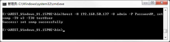
3. Execute the following command to configure the SNMP trap version to v3, and specify the SNMP v3 user testUser. To configure the SNMP trap version to v3, there must be a user with SNMP extended privileges enabled. Execute the following command, as shown in Figure 7.
hREST -H 192.168.50.137 -U admin -P Password@_ setsnmp –TV v3 –T3U testUser
Figure 7 Configuring the SNMP version and user
4. Configure the alarm sending level, as shown in Figure 8. In this example, the sending level is All.
hREST -H 192.168.50.137 -U admin -P Password@_ setsnmp –AS All
Figure 8 Configuring the alarm sending level

5. Configure the alarm trap server.
· The alarm server with sequence number 1 is enabled, the trap server address is 192.168.1.1, and the trap port is 161.
· The alarm server with sequence number 2 is enabled, the trap server address is 192.168.1.2, and the trap port is 162.
· The alarm server with sequence number 3 is disabled, the trap server address is 192.168.1.3, and the trap port is 163.
· The alarm server with sequence number 4 is enabled, the trap server address is 192.168.1.4, and the trap port is 164.
Execute the following command, as shown in Figure 9.
hREST -H 192.168.50.137 -U admin -P Password@_ setsnmp –TS [1-1-161-192.168.1.1_2-1-162-192.168.1.2_3-0-163-192.168.1.3_4-1-164-192.168.1.4]
Figure 9 Configuring the alarm trap server

Verifying configuration
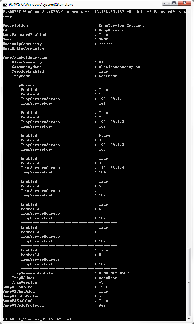
1. Execute the following command to obtain the current SNMP information, as shown in Figure 10.
hrest –H 192.168.50.137 –U admin –P Password@_ getsnmp
Figure 10 Obtaining SNMP information
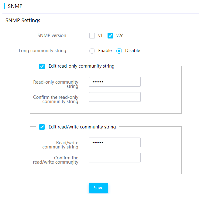
2. Log in to the HDM Web page, access the SNMP page, and verify that the long community string feature is enabled, as shown in Figure 11.
Figure 11 Viewing the SNMP page
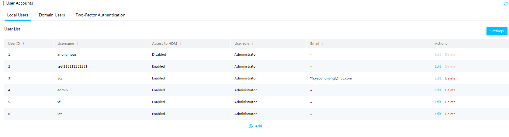
3. Enter the local users page, and verify that a new local user named testUser is added, as shown in Figure 12.
4. Enter the SNMP trap packet settings page, and verify that the configuration is the same as the actual configuration.
Example: Obtaining CPU information through hREST commands
Procedures
1. Open the folder directory D:hREST_Windows_V1.15P02 where the hREST installation package resides. Enter the bin directory, press Shift while right-clicking in the blank, and select Open command window here to open the Windows CMD.
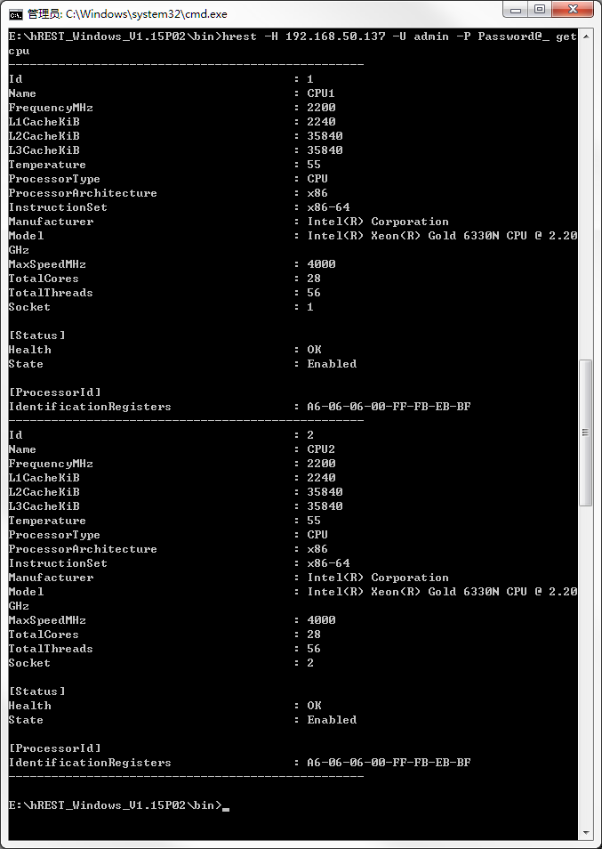
2. Execute the following command to obtain the CPU information, as shown in Figure 13.
hREST -H 192.168.50.137 -U admin -P Password@_ getcpu
Figure 13 Obtaining CPU information
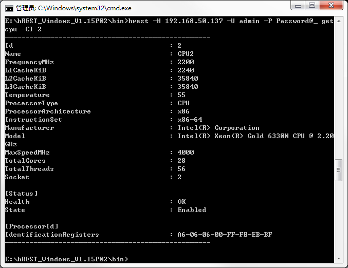
3. Execute the following command to obtain the CPU information with an ID of 2, as shown in Figure 14.
hREST -H 192.168.50.137 -U admin -P Password@_ getcpu –CI 2
Figure 14 Obtaining the CPU information with an ID of 2
Verifying configuration
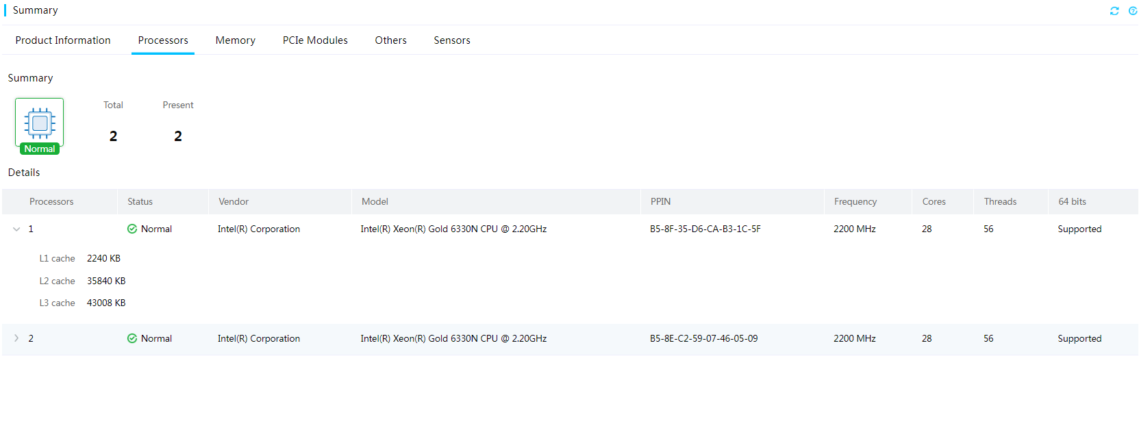
Log in to the HDM Web page, access the CPU hardware information page, and verify that the information is the same as that obtained through hREST, as shown in Figure 15.
Viewing CPU hardware information
Related documentation
H3C hREST User Guide
