- Table of Contents
-
- H3C HDM Configuration Examples-6W100
- 01-H3C Redfish Configuration Examples
- 02-H3C LDAP Configuration Examples
- 03-H3C IPMI Configuration Examples
- 04-H3C SNMP Configuration Examples
- 05-H3C HDM Mobile Configuration Examples for Remote Access to a Server Through L2TP VPN
- 06-H3C HDM Configuration Examples for Obtaining Event Logs Through the Redfish Interface
- 07-H3C HDM SMTP Configuration Examples
- 08-H3C HDM Zabbix-Based Server Monitoring Configuration Examples
- 09-H3C HDM Network Settings Configuration Examples
- 10-H3C hREST Configuration Examples for Configuring SNMP and Obtaining the CPU Information
- 11-H3C HDM Configuration Management Configuration Examples
- 12-HDM AD Configuration Examples
- 13-H3C HDM SOL Configuration Examples
- 14-HDM Unified Control Configuration Examples
- Related Documents
-
| Title | Size | Download |
|---|---|---|
| 03-H3C IPMI Configuration Examples | 263.46 KB |
H3C HDM
IPMI Configuration Examples
Copyright © 2022 New H3C Technologies Co., Ltd. All Rights Reserved.
No part of this manual may be reproduced or transmitted in any form or by any means without prior written consent of New H3C Technologies Co., Ltd.
Except for the trademarks of New H3C Technologies Co., Ltd., any trademarks that may be mentioned in this document are the property of their respective owners.
The information in this document is subject to change without notice.
Example 1: Setting the power status through the IPMI command
Example 2: Setting the next boot device through the IPMI command
Introduction
The following information provides examples for using the intelligent platform management interface (IPMI) command to manage servers, including operations through commands of string (such as power status) or the original code in hexadecimal (such as raw 0x00 0x01) types.
Prerequisites
Procedures and information in the examples might be slightly different depending on the software or hardware version of the products.
The configuration was created and verified in a lab environment, and all the servers and software were started with the factory default configuration. When you are working on a live network, make sure you understand the potential impact of every command on your network.
The following information is provided based on the assumption that you have basic knowledge of relevant IPMI features.
Applicable scenarios
The following information applies to scenarios where IPMI command lines are required to invoke HDM and manage the server quickly.
Configuration example
Network requirement
As shown in Figure 1, the server is connected to the PC through the HDM dedicated management interface and the IP addresses of HDM and PC can ping each other. Now, the following requirements are expected to be met: Set the server power status and set the next boot device on the PC via IPMItool in a command line, with the following network configuration:
· HDM management software information:
¡ IP addresses: 192.168.50.137/16
¡ Administrator account: admin
¡ Administrator password: Password@_
· PC information:
¡ IP addresses: 192.168.11.36/16
¡ Windows OS with IPMItool installed. You can download IPMItool from the Internet.
Figure 1 IPMI configuration networking

Analysis
See the relevant descriptions in H3C HDM IPMI Basic Command Reference Manual to use IPMItool for operations. The following analysis and procedure are also instructive for using tools other than IPMItool.
The basic analysis is:
1. Query the current status of devices.
2. Confirm the configuration parameters and send commands to modify the configuration.
3. Send the query command again to confirm that the modification succeeded.
Software versions used
This example was created and verified on the HDM-2.32 version and the IPMItool version is 1.8.18.
Restrictions and guidelines
The restrictions and guidelines for using the IPMI command are:
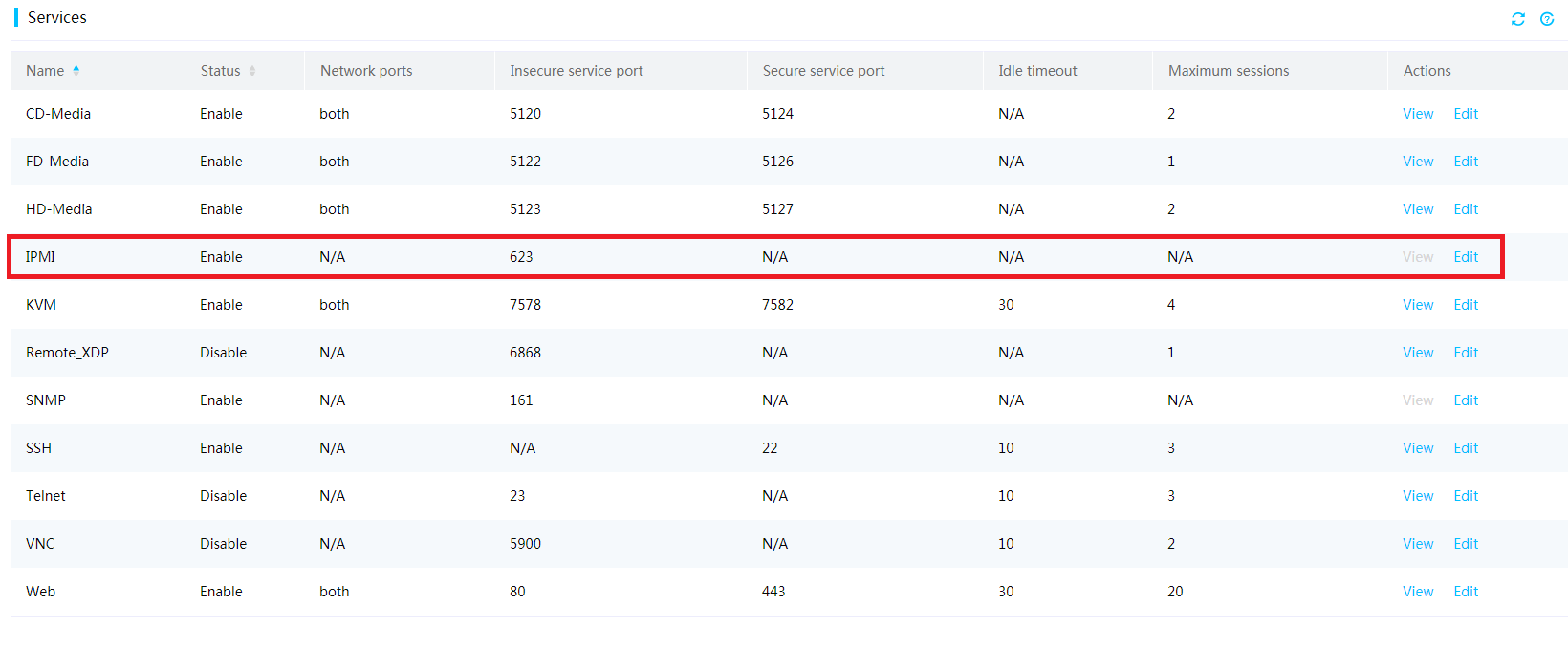
· Make sure the IPMI service of the HDM is enabled, as shown in Figure 2.
· Confirm that the non-security port ID is 623 by default.
¡ If the non-security port ID is 623, you do not need to specify the port ID when inputting the IPMI command.
¡ If the non-security port ID is not 623, the -p parameter is required to specify the port ID when the IPMI command is input.
Example 1: Setting the power status through the IPMI command
Procedures
Obtaining the current power status
1. Open the E:\ipmitool-1.8.18 directory where the ipmitool.exe file locates. Press and hold Shift, and right-click a blank space to select Open the command window here (W).
2. Execute the following command on the Windows CMD CLI to obtain the current power status.
ipmitool –I lanplus –H 192.168.50.137 –U admin –P Password@_ power status
|
|
NOTE: An IPMI command uses the ipmitool -I connect_type -H hostname -U username -P password <command> format, where: · -I connect_type—Specifies the connection method used to access the device to be managed. The connect_type argument is fixed to lanplus, which indicates that the device to be managed will be accessed as required in the IPMI 2.0 specification. · -H hostname—Specifies the IP address of the device to be managed. · -U username—Specifies the HDM username of the device to be managed. · -P password—Specifies the HDM password of the device to be managed. · <command>—Specifies the action to be taken. This argument can be a string (power status for example) or a hexadecimal raw code (raw 0x00 0x01 for example). · -L—Specifies the session privilege. The default value is Administrator. It is required by users and operators. |
3. As shown in Figure 3, the server is on.
Figure 3 Obtaining the server status

Powering off the server
As shown in Figure 4, execute the following command to power off the server.
ipmitool –I lanplus –H 192.168.50.137 –U admin –P Password@_ power off
Figure 4 Powering off the server

Verifying the configuration
1. Execute the following command to query the server power status again.
ipmitool –I lanplus –H 192.168.50.137 –U admin –P Password@_ power status
2. As shown in Figure 5, you can see that the server is off.
Figure 5 Obtaining the power status again

Example 2: Setting the next boot device through the IPMI command
Procedures
Querying the next boot device
Go to the directory of IPMItool from the Windows CLI, as shown in Figure 6. Execute the following command to obtain the next boot device information of the server set by the user.
ipmitool –I lanplus –H 192.168.50.137 –U admin –P Password@_ raw 0x00 0x09 0x05 0x00 0x00
Figure 6 Querying the next boot device
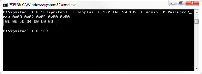
The returned result is 01 05 c0 04 00 00 00. You need to parse this byte code in hexadecimal according to Table 1.
|
|
NOTE: For more detailed descriptions of the IPMI command, see H3C HDM IPMI Basic Command Reference. |
The Data[3] in the current returned result is 0xc0, which is equal to 1100 0000 in binary. The digits are Bit 7–Bit 0 starting from the left. Therefore, Bit 7 is 1, and Bit 6 is also 1. According to the description, the boot device is a permanent boot device.
The Data[4] in the current returned result is 0x04, which is equal to 0000 0100 in binary. Digits at Bit 5–Bit 2 are 0001, meaning the boot device is PXE.
Table 1 Returned result descriptions
|
Returned result |
Remarks |
|
Data[3] |
Boot period of validity · Bit 7 indicates whether the boot setting is valid. ¡ 0: Invalid ¡ 1: Valid · Bit 6 indicates whether the boot is one-off or permanent. ¡ 0: One-off. The setting only takes effect at the next boot and then resumes to the default value. ¡ 1: Permanent · Other bits are set to 0 by default. |
|
Data[4] |
Server boot device · Bit 5–Bit 2: Boot device ¡ 0000b: Not specified ¡ 0001b: PXE ¡ 0110b: BIOS setup ¡ 0010b: HDD ¡ 0101b: CDROM · Other bits are set to 0 by default. |
Setting the next boot device
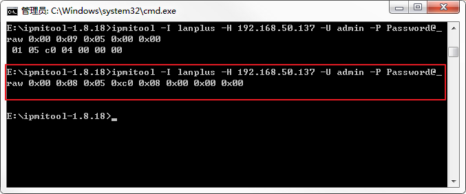
As shown in Figure 7, execute the following command to set the boot item to HDD.
ipmitool –I lanplus –H 192.168.50.137 –U admin –P Password@_ raw 0x00 0x08 0x05 0xc0 0x08 0x00 0x00 0x00
Figure 7 Setting the next boot device through the IPMI command
Specific parameter descriptions of the command are shown in Table 2. Since the boot item is set to HDD, it requires to:
· Set Data[4] to 0xc0, which is equal to 1100 0000 in binary. The digits are Bit 7–Bit 0 starting from left. Therefore, Bit 7 is 1, and Bit 6 is 1, meaning the boot item is valid permanently.
· Set Data[5] to 0x08, which is equal to 0000 1000 in binary. The digits are Bit 7–Bit 0 starting from the left. Therefore, Bit 5–Bit 2 is 0010, meaning HDD.
Table 2 Descriptions of setting the system boot commands
|
Byte |
Value/Indication |
|
Data[4] |
Setting boot period of validity · Bit 7 indicates whether the boot setting is valid. ¡ 0: Invalid ¡ 1: Valid · Bit 6 indicates whether the boot is one-off or permanent. ¡ 0: One-off. The setting of the boot device only takes effect at the next boot and then resumes to the default value. ¡ 1: Permanent · Other bits are set to 0 by default. |
|
Data[5] |
· Setting the server boot device · Bit 5–Bit 2: Boot device ¡ 0000b: Not specified ¡ 0001b: PXE ¡ 0110b: BIOS setup ¡ 0010b: HDD ¡ 0101b: CDROM · Other bits are set to 0 by default. |
Verifying the configuration
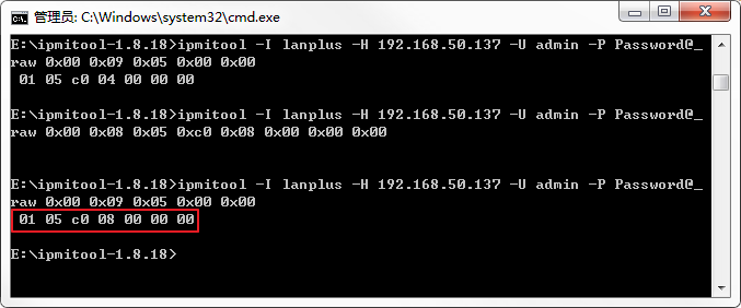
Execute the following command, and query the next boot device information again, as shown in Figure 8, to confirm that the settings are successful.
ipmitool –I lanplus –H 192.168.50.137 –U admin –P Password@_ raw 0x00 0x09 0x05 0x00 0x00
Figure 8 Querying the next boot device again
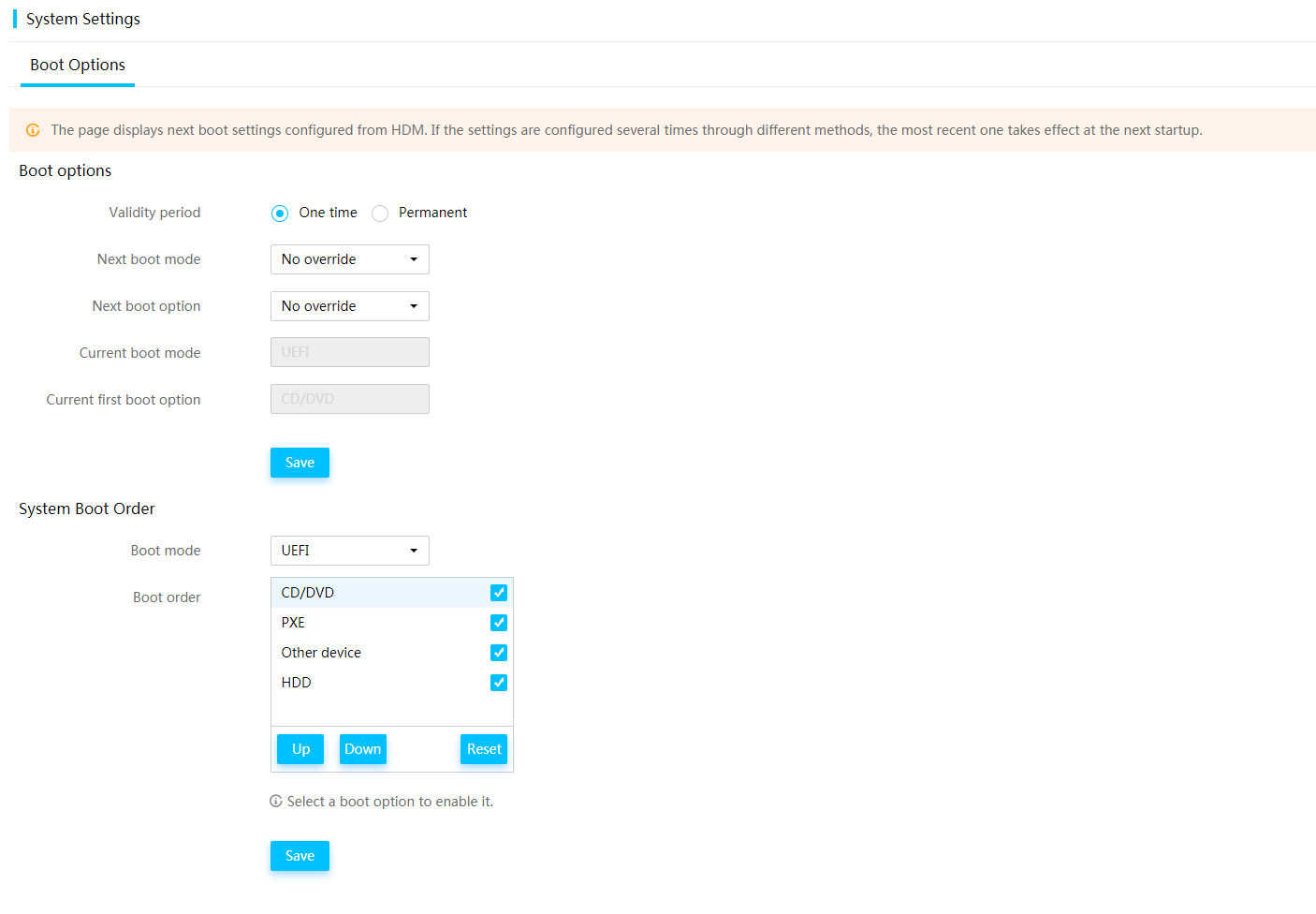
Log in to HDM and query the system boot item settings. As shown in Figure 9, the boot item is permanently valid and the next boot device is modified to HDD.
Figure 9 Querying the system boot device on the HDM page
Related documentation
· H3C HDM IPMI Basic Command Reference
· H3C HDM IPMI Technology White Paper
