- Table of Contents
-
- H3C HDM Configuration Examples-6W100
- 01-H3C Redfish Configuration Examples
- 02-H3C LDAP Configuration Examples
- 03-H3C IPMI Configuration Examples
- 04-H3C SNMP Configuration Examples
- 05-H3C HDM Mobile Configuration Examples for Remote Access to a Server Through L2TP VPN
- 06-H3C HDM Configuration Examples for Obtaining Event Logs Through the Redfish Interface
- 07-H3C HDM SMTP Configuration Examples
- 08-H3C HDM Zabbix-Based Server Monitoring Configuration Examples
- 09-H3C HDM Network Settings Configuration Examples
- 10-H3C hREST Configuration Examples for Configuring SNMP and Obtaining the CPU Information
- 11-H3C HDM Configuration Management Configuration Examples
- 12-HDM AD Configuration Examples
- 13-H3C HDM SOL Configuration Examples
- 14-HDM Unified Control Configuration Examples
- Related Documents
-
| Title | Size | Download |
|---|---|---|
| 09-H3C HDM Network Settings Configuration Examples | 605.79 KB |
H3C HDM
Network Settings Configuration Examples
Copyright © 2023 New H3C Technologies Co., Ltd. All rights reserved.
No part of this manual may be reproduced or transmitted in any form or by any means without prior written consent of New H3C Technologies Co., Ltd.
Except for the trademarks of New H3C Technologies Co., Ltd., any trademarks that may be mentioned in this document are the property of their respective owners.
The information in this document is subject to change without notice.
Example: Configuring network settings
Configuring the dedicated port
Configuring the Wi-Fi information
Verifying the dedicated port settings
Verifying the shared port settings
Introduction
The following information provides examples for configuring the HDM dedicated and shared network ports and Wi-Fi information through the HDM Web page.
Prerequisites
Procedures and information in the examples might be slightly different depending on the software or hardware version of the products.
The configuration was created and verified in a lab environment, and all the servers and software were started with the factory default configuration. When you are working on a live network, make sure you understand the potential impact of every command on your network.
The following information is provided based on the assumption that you have learned about functions related to HDM network settings.
Applicable scenarios
The following information applies to the scenarios where HDM network settings need to be completed to realize configuration of various ports and integrate the HDM management network with the current network management system.
Example: Configuring network settings
Network analysis
As shown in Figure 1, the HDM dedicated and shared ports of the target server (H3C UniServer R4900 G5 in this example, or R4900 G5 for short) are connected to client A and client B through a switch. On client A, log in to the HDM Web page using the default IP address of the HDM dedicated network port, configure the IP addresses of the dedicated and shared network ports and wireless network. It is required that client A can navigate to HDM through the dedicated network port, shared network port, or wireless network.
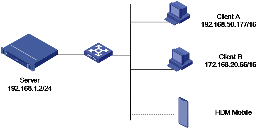
· HDM management software information:
¡ IP address of the dedicated network port: 192.168.1.2/24 (Default IP address)
¡ Administrator account: admin
¡ Administrator password: Password@_
· Client A information:
¡ IP addresses: 192.168.55.177/16
· Client B information:
¡ IP addresses: 172.168.20.66/16
Software versions used
This example was created and verified on HDM 2.90 and HDM Mobile 2.0.0.
Restrictions and guidelines
· When the network port is in the normal mode, configure the IP addresses of the HDM shared network port, dedicated network port and wireless network in three different network segments. The IP addresses cannot be the same; otherwise, the network failure may occur.
· Do not disable all HDM network ports at the same time; otherwise, users will not be able to navigate to the HDM Web interface.
· After the HDM network configuration is modified, the browser session will be disconnected. It may take several minutes before the HDM Web interface can be reconnected.
· After modifying the HDM network settings, wait until the configuration takes effect, and then power off and restart the server.
· A mobile client may fail to access the Internet after it is connected to the HDM wireless network.
· Ensure that HDM Mobile has been downloaded and installed on the mobile client.
Procedures
Logging in to HDM
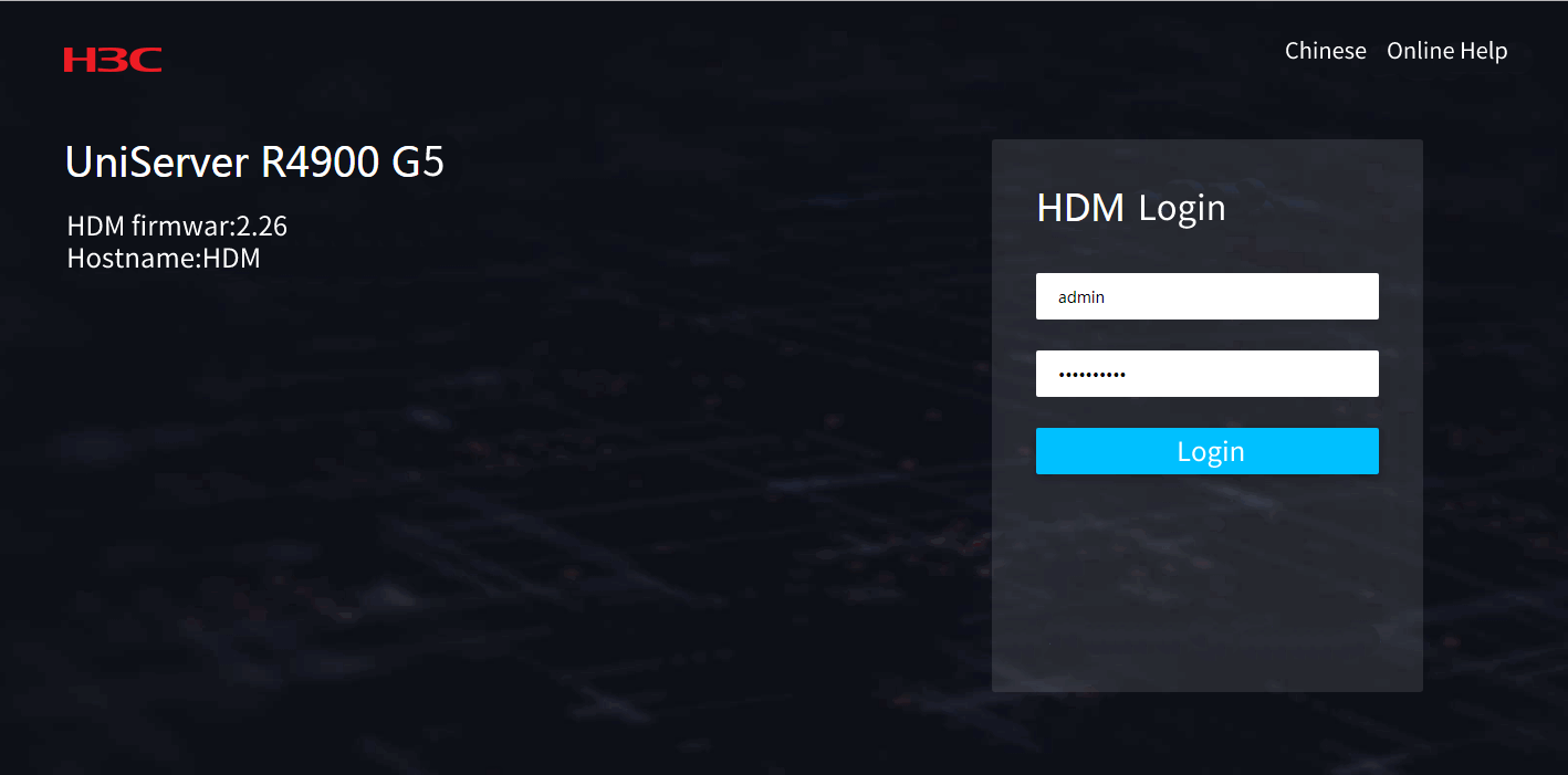
1. Open a browser on client A, and enter the default IP address of the HDM dedicated port 192.168.1.2 in the address bar to navigate to the HDM login page, as shown in Figure 2. On the HDM login page, enter the default username admin and the default password Password@_, and then click Log In.
2. Select Network > Dedicated Port, and view the general information, IP address and VLAN information of the dedicated port, as shown in Figure 3.

Configuring the dedicated port
The HDM dedicated network port is designed to handle HDM management traffic. The default IPv4 address is 192.168.1.2/24, and the IPv6 addresses are obtained automatically by default through DHCP.
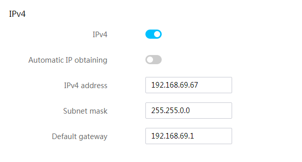
1. Click Configure in the upper right corner of the Dedicated Port tab. On the dedicated port configuration page that opens, configure the IP address and VLAN information, as shown in Figure 4.
a. Configure the IPv4 address. In this example, a static IP address is configured.
- Enable the IPv4 configuration function.
- Disable Automatic IP obtaining.
- Set IPv4 address to 192.168.50.137.
- Set Subnet mask to 255.255.255.0.
- Set Default gateway to 0.0.0.0.
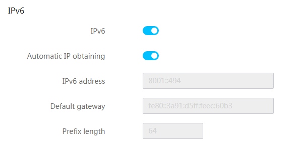
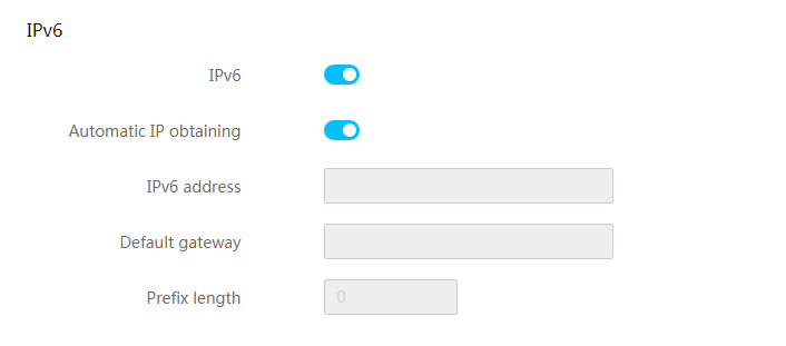
b. Configure the IPv6 address. In this example, the IP address is obtained automatically through DHCP.
- Enable the IPv6 configuration function.
- Enable Automatic IP obtaining.
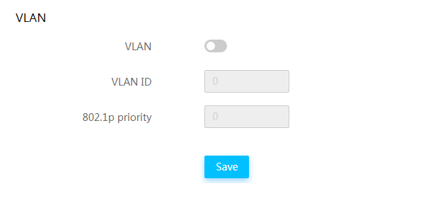
c. (Optional) Configure the VLAN information.
- Enable the VLAN configuration function.
- Configure the VLAN ID and VLAN priority. In this example, the default values are retained.
Figure 4 Dedicated port configuration page
2. Click Save. HDM restarts automatically to make the configuration take effect. After the configuration takes effect, you need to log in to HDM again.
Configuring the shared port
The HDM shared port can handle the management traffic of HDM and service traffic of the server simultaneously. It automatically obtains the IP address through DHCP by default.
1. Open a browser on client A, and enter the IP address of the HDM dedicated port 192.168.50.137 in the address bar to navigate to the HDM login page. On the HDM login page, enter the default username admin and the default password Password@_, and then click Login to log in to HDM again.
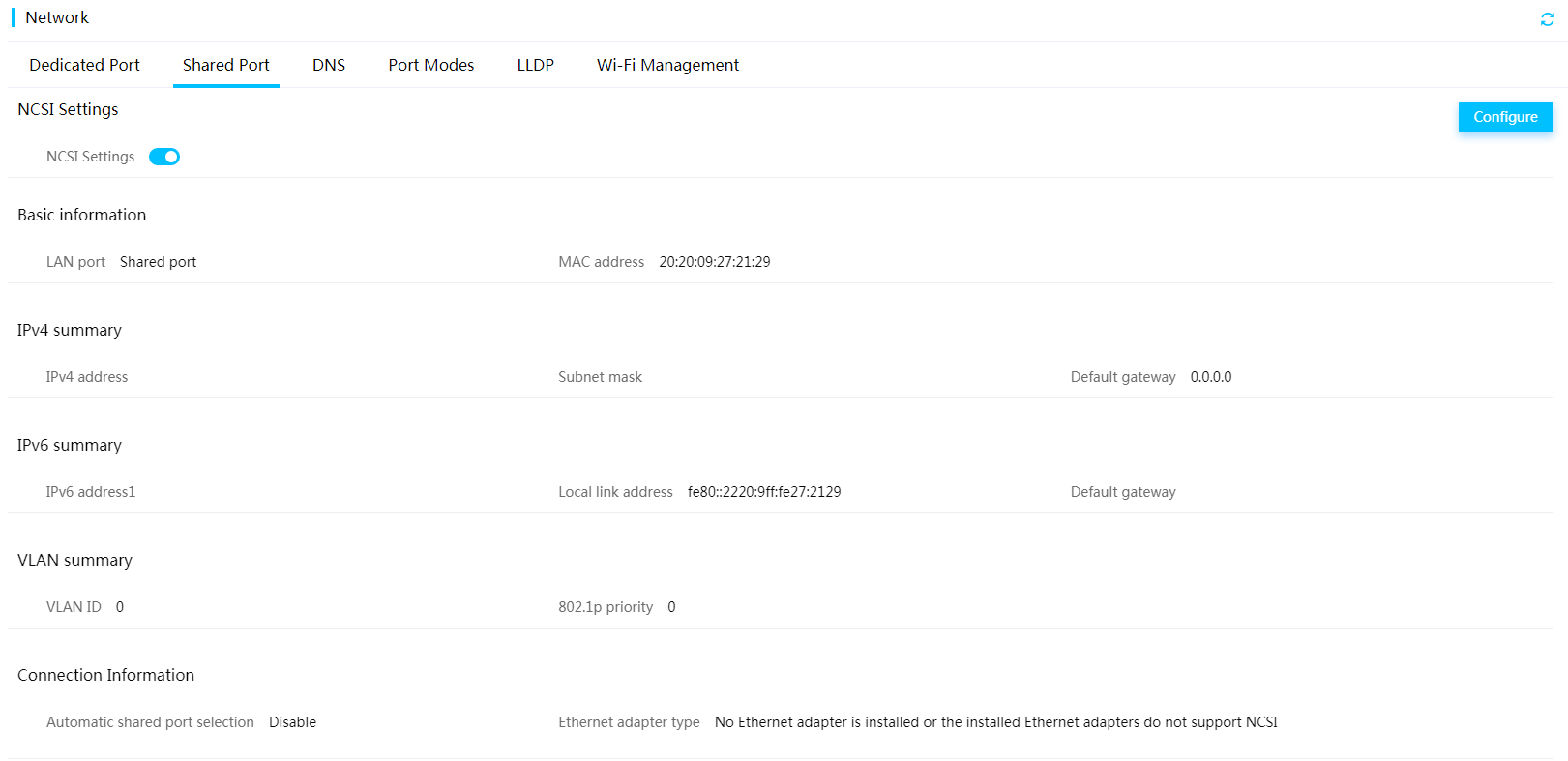
2. Select Network > Shared Port, and view the information of the shared port, as shown in Figure 5.
3. Click Configure in the upper right corner. On the shared port configuration page that opens, configure the LAN, IP address and VLAN information, as shown in Figure 6.
a. Enable the LAN configuration function.
b. Configure the IPv4 address. In this example, a static IP address is configured.
- Enable the IPv4 configuration function.
- Disable Automatic IP obtaining.
- Set IPv4 address to 172.168.20.12.
- Set Subnet mask to 255.255.255.0.
- Set Default gateway to 0.0.0.0.
c. Configure the IPv6 address. In this example, the IP address is obtained automatically through DHCP.
- Enable the IPv6 configuration function.
- Enable Automatic IP obtaining.
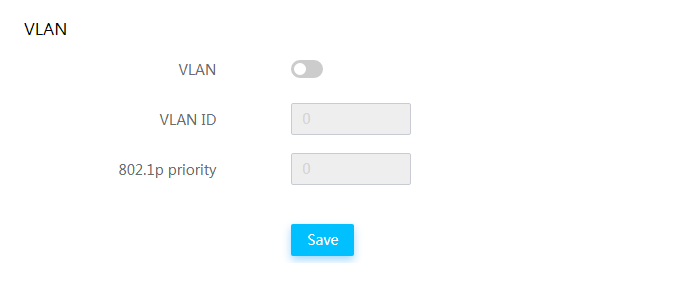
d. (Optional) Configure the VLAN information.
- Enable the VLAN configuration function.
- Configure the VLAN ID and VLAN priority. In this example, the default values are retained.
Figure 6 Shared port configuration page

4. Click Save. HDM restarts automatically to make the configuration take effect. After the configuration takes effect, you need to log in to HDM again.
Configuring the Wi-Fi information
1. Use a USB-C to USB-A adapter cable to connect the USB WiFi module to the dedicated management port on the left mounting ear of the server.
2. Log in to the HDB Web page again through the HDM dedicated port or shared port, and the Wi-Fi Management page, as shown in Figure 7.
Figure 7 Wi-Fi Management page

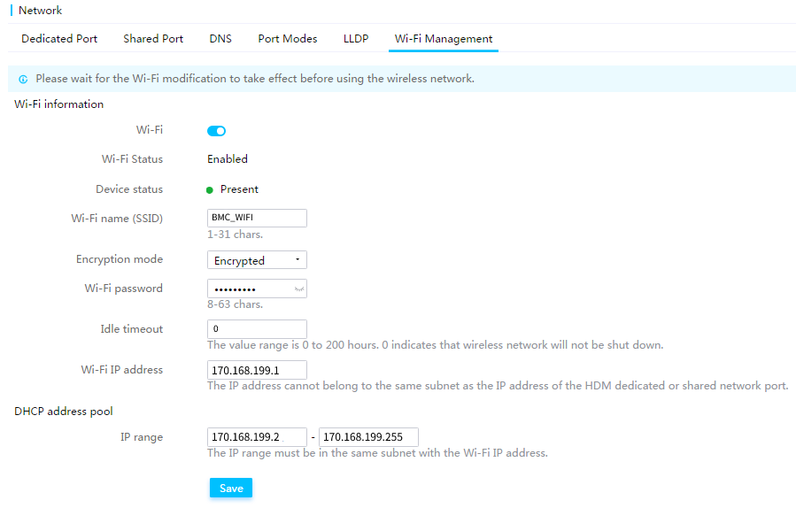
3. Configure the Wi-Fi information, as shown in Figure 8.
¡ Wi-Fi name: BMC_WiFi
¡ Encryption mode: Unencrypted (Default)
¡ Idle timeout: 0, indicating that the Wi-Fi network will not be automatically disconnected.
¡ Wi-Fi IP address: 170.168.199.1. The subnet mask is 255.255.255.0 by default.
¡ DHCP address pool:170.168.199.2 to 170.168.199.255
Figure 8 Wi-Fi information configuration page
4. Click Save. The Wi-Fi settings take effect automatically after a period of time.
Verifying the configuration
Verifying the dedicated port settings
1. Open a browser on client A, and enter the IP address of the HDM dedicated port 192.168.50.137 in the address bar to navigate to the HDM login page. On the HDM login page, enter the default username admin and the default password Password@_, and then click Login to log in to HDM again.
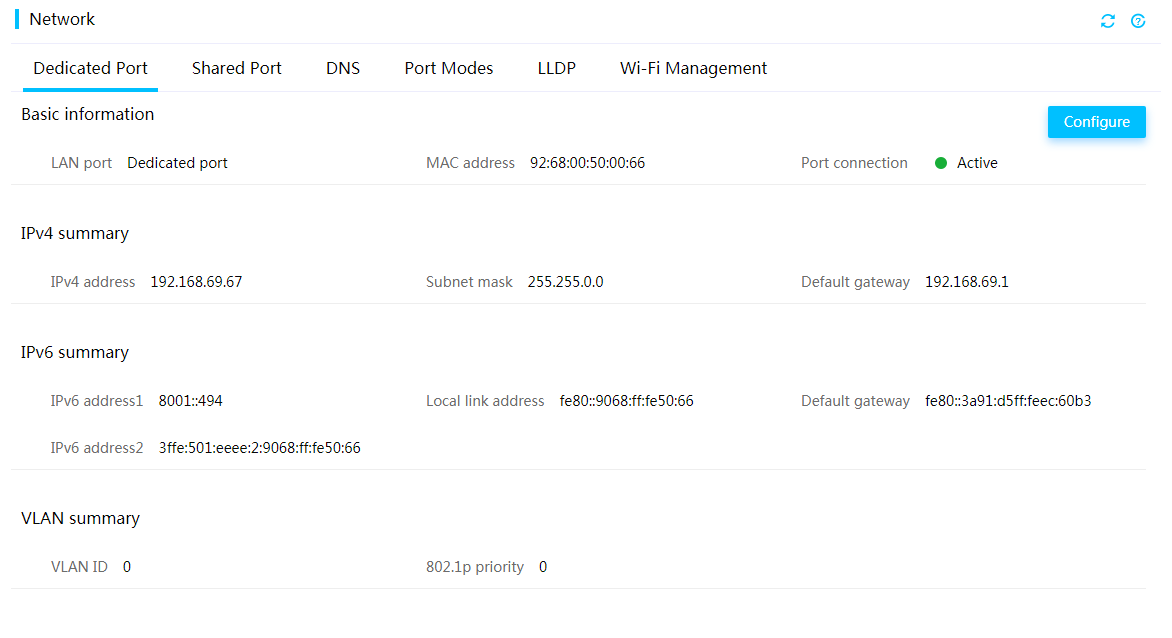
2. Select Network > Dedicated Port, and check the settings of the HDM dedicated port, as shown in Figure 9.
Figure 9 Checking the dedicated port information
Verifying the shared port settings
1. Open a browser on client B, and enter the IP address of the HDM shared port 172.168.20.12 in the address bar to navigate to the HDM login page. On the HDM login page, enter the default username admin and the default password Password@_, and then click Log In.
2. Select Network > Shared Port, and check the settings of the shared port.
Verifying the Wi-Fi settings
1. Open the mobile client, and navigate to the WLAN page.
2. Enable the WLAN function, and connect to the BMC_WiFi network.
3. Open HDM Mobile, and navigate to the Device Management page.
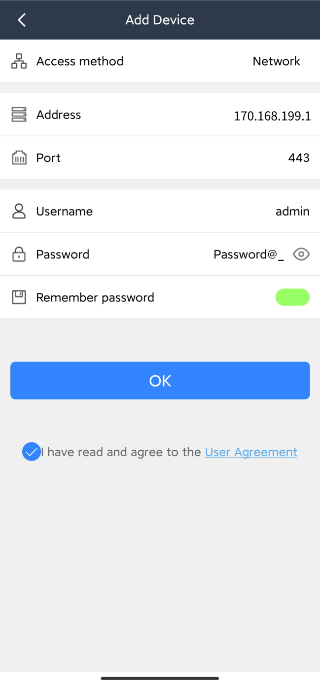
4. Tap ![]() in the upper right corner to navigate to the Add
Device page, and enter the device information of the server, as shown in
Figure 10.
in the upper right corner to navigate to the Add
Device page, and enter the device information of the server, as shown in
Figure 10.
¡ IP address: 170.168.199.1
¡ Port: 443 (Default)
¡ Username: admin
¡ Administrator password: Password@_
¡ (Optional) Remember the password: Enable
5. After the device is added, it is displayed in the device list, as shown in Figure 11.
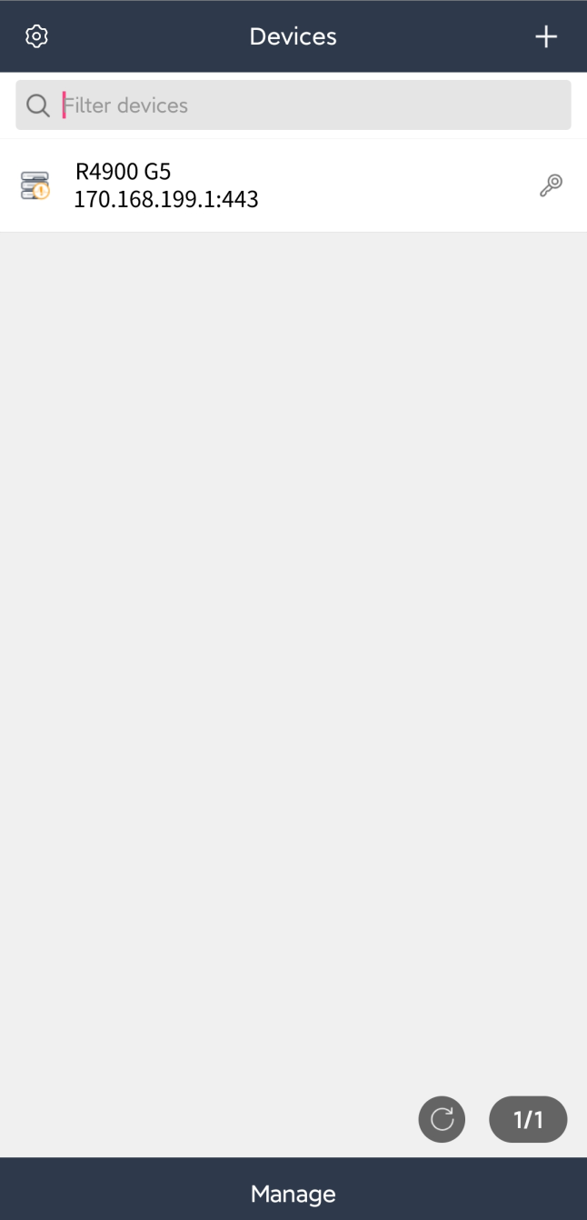
6. Tap R4900 G5 in the device list to navigate to the HDM Mobile homepage of the server, as shown in Figure 12.

Related documentation
· H3C Servers HDM User Guide
· H3C Servers HDM H3C User Guide
