- Table of Contents
-
- H3C S6820 Switch Series Configuration Examples-Release 630x-6W100
- 01-Login Management Configuration Examples
- 02-RBAC Configuration Examples
- 03-Software Upgrade Examples
- 04-ISSU Configuration Examples
- 05-Software Patching Examples
- 06-Ethernet Link Aggregation Configuration Examples
- 07-Port Isolation Configuration Examples
- 08-Spanning Tree Configuration Examples
- 09-VLAN Configuration Examples
- 10-VLAN Tagging Configuration Examples
- 11-DHCP Snooping Configuration Examples
- 12-Cross-Subnet Dynamic IP Address Allocation Configuration Examples
- 13-IPv6 over IPv4 Manual Tunneling with OSPFv3 Configuration Examples
- 14-ISATAP Tunnel and 6to4 Tunnel Configuration Examples
- 15-IPv6 over IPv4 GRE Tunnel Configuration Examples
- 16-GRE with OSPF Configuration Examples
- 17-OSPF Configuration Examples
- 18-IS-IS Configuration Examples
- 19-BGP Configuration Examples
- 20-Policy-Based Routing Configuration Examples
- 21-OSPFv3 Configuration Examples
- 22-IPv6 IS-IS Configuration Examples
- 23-Routing Policy Configuration Examples
- 24-IGMP Snooping Configuration Examples
- 25-IGMP Configuration Examples
- 26-BIDIR-PIM Configuration Examples
- 27-Multicast VPN Configuration Examples
- 28-MLD Snooping Configuration Examples
- 29-IPv6 Multicast VLAN Configuration Examples
- 30-Basic MPLS Configuration Examples
- 31-MPLS L3VPN Configuration Examples
- 32-ACL Configuration Examples
- 33-Control Plane-Based QoS Policy Configuration Examples
- 34-Traffic Policing Configuration Examples
- 35-GTS and Rate Limiting Configuration Examples
- 36-Priority Mapping and Queue Scheduling Configuration Examples
- 37-Traffic Filtering Configuration Examples
- 38-AAA Configuration Examples
- 39-Port Security Configuration Examples
- 40-Portal Configuration Examples
- 41-SSH Configuration Examples
- 42-IP Source Guard Configuration Examples
- 43-Ethernet OAM Configuration Examples
- 44-CFD Configuration Examples
- 45-DLDP Configuration Examples
- 46-VRRP Configuration Examples
- 47-BFD Configuration Examples
- 48-NTP Configuration Examples
- 49-SNMP Configuration Examples
- 50-NQA Configuration Examples
- 51-Mirroring Configuration Examples
- 52-sFlow Configuration Examples
- 53-FCoE Configuration Examples
- 54-OpenFlow Configuration Examples
- 55-MAC Address Table Configuration Examples
- 56-Static Multicast MAC Address Entry Configuration Examples
- 57-IP Unnumbered Configuration Examples
- 58-MVRP Configuration Examples
- 59-MCE Configuration Examples
- 60-Congestion Avoidance and Queue Scheduling Configuration Examples
- 61-Attack Protection Configuration Examples
- 62-Smart Link Configuration Examples
- 63-RRPP Configuration Examples
- 64-BGP Route Selection Configuration Examples
- 65-IS-IS Route Summarization Configuration Examples
- 66-IRF Configuration Examples
- 67-MPLS OAM Configuration Examples
- 68-MPLS TE Configuration Examples
- 69-NetStream Configuration Examples
- 70-VXLAN Configuration Examples
- 71-DRNI Configuration Examples
- 72-DRNI and EVPN Configuration Examples
- 73-EVPN-DCI over an MPLS L3VPN Network Configuration Examples
- 74-S-MLAG Configuration Examples
- 75-MPLS SR Configuration Examples
- 76-Puppet Configuration Examples
- Related Documents
-
| Title | Size | Download |
|---|---|---|
| 73-EVPN-DCI over an MPLS L3VPN Network Configuration Examples | 88.06 KB |
|
|
|
H3C S6820 Switches |
|
EVPN-DCI over an MPLS L3VPN Network |
|
Configuration Examples |
Copyright © 2020 New H3C Technologies Co., Ltd. All rights reserved.
No part of this manual may be reproduced or transmitted in any form or by any means without prior written consent of New H3C Technologies Co., Ltd.
Except for the trademarks of New H3C Technologies Co., Ltd., any trademarks that may be mentioned in this document are the property of their respective owners.
The information in this document is subject to change without notice.
Contents
General restrictions and guidelines
Example: Configuring IPv4 EVPN-DCI over an MPLS L3VPN network
Configuring the system operating mode
Configuring IP addresses for interfaces
Configuring OSPF on the switches
Creating the VXLANs and EVPN instances
Configuring L3 VXLAN IDs and VSI interfaces
Disabling remote MAC address learning and remote ARP learning
Mapping Ethernet service instances to VSIs
Establishing BGP EVPN peer relationship within a data center
Establishing MPLS L3VPN connections between ASs
Configuring the BGP EVPN address family and the BGP VPNv4 address family to exchange routes
Introduction
This document provides examples for configuring EVPN-DCI over an MPLS L3VPN network.
Prerequisites
This document is not restricted to specific software or hardware versions.
The configuration examples in this document were created and verified in a lab environment, and all the devices were started with the factory default configuration. When you are working on a live network, make sure you understand the potential impact of every command on your network.
This document assumes that you have basic knowledge of MPLS L3VPN and EVPN.
General restrictions and guidelines
Before you configure EVPN on a device, you must perform the following tasks:
1. Set the system operating mode to standard mode by using the system-working-mode command in system view.
2. Save the running configuration.
3. Reboot the device.
Example: Configuring IPv4 EVPN-DCI over an MPLS L3VPN network
Network configuration
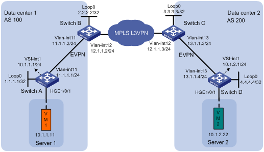
As shown in Figure 1:
· Data center 1 and data center 2 are interconnected through an MPLS L3VPN network. The two data centers can communicate with each other through the MPLS L3VPN network.
· Switch A and Switch D are distributed EVPN gateways in the data centers.
· Switch B and Switch C act as both EVPN EDs and MPLS L3VPN PEs.
Analysis
For the switches within a data center to reach each other, configure a routing protocol on the switches to advertise routes for interfaces (including the loopback interfaces). In this example, OSPF is used.
To enable communication between the data centers, you must perform the following tasks on Switch B and Switch C:
· Configure both MPLS L3VPN and EVPN.
· Configure the BGP EVPN address family and the BGP VPNv4 address family to exchange routes.
Software versions used
This configuration example was created and verified on R6301.
Restrictions and guidelines
As a best practice to ensure correct traffic forwarding, configure the same MAC address for all VSI interfaces on an EVPN gateway.
When you configure L3 VXLAN IDs for VSI interfaces, make sure the same route targets are configured for the VPN instances associated with these VSI interfaces.
Procedures
Configuring the system operating mode
# Set the system operating mode to standard on Switch A, and reboot the switch for the mode change to take effect.
<SwitchA> system-view
[SwitchA] system-working-mode standard
[SwitchA] quit
<SwitchA> reboot
# Set the system operating mode of Switch B, Switch C, and Switch D to standard. The method is the same as Switch A. (Details not shown.)
Configuring IP addresses for interfaces
# Configure IP addresses for interfaces on Switch A.
<SwitchA> system-view
[SwitchA] vlan 11
[SwitchA-vlan11] quit
[SwitchA] interface hundredgige 1/0/2
[SwitchA-HundredGigE1/0/2] port link-type trunk
[SwitchA-HundredGigE1/0/2] port trunk permit vlan 11
[SwitchA-HundredGigE1/0/2] undo shutdown
[SwitchA-HundredGigE1/0/2] quit
[SwitchA] interface vlan-interface 11
[SwitchA-Vlan-interface11] ip address 11.1.1.1 24
[SwitchA-Vlan-interface11] undo shutdown
[SwitchA-Vlan-interface11] quit
[SwitchA] interface loopback 0
[SwitchA-LoopBack0] ip address 1.1.1.1 32
[SwitchA-LoopBack0] undo shutdown
[SwitchA-LoopBack0] quit
# Configure IP addresses for interfaces on Switch B, Switch C, and Switch D. The method is the same as Switch A. (Details not shown.)
Configuring OSPF on the switches
# On Switch A, specify interfaces attached to the specified network to run OSPF.
[SwitchA] ospf 1
[SwitchA-ospf-1] area 0
[SwitchA-ospf-1-area-0.0.0.0] network 1.1.1.1 0.0.0.0
[SwitchA-ospf-1-area-0.0.0.0] network 11.1.1.0 0.0.0.255
[SwitchA-ospf-1-area-0.0.0.0] quit
[SwitchA-ospf-1] quit
# On Switch B, specify interfaces attached to the specified network to run OSPF.
<SwitchB> system-view
[SwitchB] ospf 1
[SwitchB-ospf-1] import-route bgp
[SwitchB-ospf-1] area 0
[SwitchB-ospf-1-area-0.0.0.0] network 2.2.2.2 0.0.0.0
[SwitchB-ospf-1-area-0.0.0.0] network 11.1.1.0 0.0.0.255
[SwitchB-ospf-1-area-0.0.0.0] quit
[SwitchB-ospf-1] quit
# On Switch C, specify interfaces attached to the specified network to run OSPF.
<SwitchC> system-view
[SwitchC] ospf 1
[SwitchC-ospf-1] import-route bgp
[SwitchC-ospf-1] area 0
[SwitchC-ospf-1-area-0.0.0.0] network 3.3.3.3 0.0.0.0
[SwitchC-ospf-1-area-0.0.0.0] network 13.1.1.0 0.0.0.255
[SwitchC-ospf-1-area-0.0.0.0] quit
[SwitchC-ospf-1] quit
# On Switch D, specify interfaces attached to the specified network to run OSPF.
<SwitchD> system-view
[SwitchD] ospf 1
[SwitchD-ospf-1] area 0
[SwitchD-ospf-1-area-0.0.0.0] network 4.4.4.4 0.0.0.0
[SwitchD-ospf-1-area-0.0.0.0] network 13.1.1.0 0.0.0.255
[SwitchD-ospf-1-area-0.0.0.0] quit
[SwitchD-ospf-1] quit
Creating the VXLANs and EVPN instances
Configuring Switch A
# Enable L2VPN.
[SwitchA] l2vpn enable
# Create VSI vpn1 and VXLAN 10.
[SwitchA] vsi vpn1
[SwitchA-vsi-vpn1] vxlan 10
[SwitchA-vsi-vpn1-vxlan-10] quit
# Create an EVPN instance on VSI vpn1. Configure the switch to automatically generate an RD and a route target for the EVPN instance.
[SwitchA-vsi-vpn1] evpn encapsulation vxlan
[SwitchA-vsi-vpn1-evpn-vxlan] route-distinguisher auto
[SwitchA-vsi-vpn1-evpn-vxlan] vpn-target auto
[SwitchA-vsi-vpn1-evpn-vxlan] quit
[SwitchA-vsi-vpn1] quit
Configuring Switch D
# Enable L2VPN.
[SwitchD] l2vpn enable
# Create VSI vpn1 and VXLAN 20.
[SwitchD] vsi vpn1
[SwitchD-vsi-vpn1] vxlan 20
[SwitchD-vsi-vpn1-vxlan-20] quit
# Create an EVPN instance on VSI vpn1. Configure the switch to automatically generate an RD and a route target for the EVPN instance.
[SwitchD-vsi-vpn1] evpn encapsulation vxlan
[SwitchD-vsi-vpn1-evpn-vxlan] route-distinguisher auto
[SwitchD-vsi-vpn1-evpn-vxlan] vpn-target auto
[SwitchD-vsi-vpn1-evpn-vxlan] quit
[SwitchD-vsi-vpn1] quit
Configuring L3 VXLAN IDs and VSI interfaces
Configuring Switch A
# Configure RD and route target settings for VPN instance vpna.
[SwitchA] ip vpn-instance vpna
[SwitchA-vpn-instance-vpna] route-distinguisher 1:1
[SwitchA-vpn-instance-vpna] address-family ipv4
[SwitchA-vpn-ipv4-vpna] vpn-target 2:2
[SwitchA-vpn-ipv4-vpna] quit
[SwitchA-vpn-instance-vpna] address-family evpn
[SwitchA-vpn-evpn-vpna] vpn-target 1:1
[SwitchA-vpn-evpn-vpna] quit
[SwitchA-vpn-instance-vpna] quit
# Configure VSI-interface 1 as a distributed gateway.
[SwitchA] interface vsi-interface 1
[SwitchA-Vsi-interface1] ip binding vpn-instance vpna
[SwitchA-Vsi-interface1] ip address 10.1.1.1 24
[SwitchA-Vsi-interface1] mac-address 1-1-1
[SwitchA-Vsi-interface1] distributed-gateway local
[SwitchA-Vsi-interface1] local-proxy-arp enable
[SwitchA-Vsi-interface1] quit
# Create VSI-interface 2. Associate VSI-interface 2 with VPN instance vpna, and configure the L3 VXLAN ID as 1000 for the VPN instance.
[SwitchA] interface vsi-interface 2
[SwitchA-Vsi-interface2] ip binding vpn-instance vpna
[SwitchA-Vsi-interface2] l3-vni 1000
[SwitchA-Vsi-interface2] quit
# Specify VSI-interface 1 as the gateway interface for VSI vpn1.
[SwitchA] vsi vpn1
[SwitchA-vsi-vpn1] gateway vsi-interface 1
[SwitchA-vsi-vpn1] quit
Configuring Switch B
# Enable L2VPN.
[SwitchB] l2vpn enable
# Configure RD and route target settings for VPN instance vpna.
[SwitchB] ip vpn-instance vpna
[SwitchB-vpn-instance-vpna] route-distinguisher 1:2
[SwitchB-vpn-instance-vpna] address-family ipv4
[SwitchB-vpn-ipv4-vpna] vpn-target 2:2
[SwitchB-vpn-ipv4-vpna] quit
[SwitchB-vpn-instance-vpna] address-family evpn
[SwitchB-vpn-evpn-vpna] vpn-target 1:1
[SwitchB-vpn-evpn-vpna] quit
[SwitchB-vpn-instance-vpna] quit
# Create VSI-interface 1. Associate VSI-interface 1 with VPN instance vpna, and configure the L3 VXLAN ID as 1000 for the VPN instance.
[SwitchB] interface vsi-interface 1
[SwitchB-Vsi-interface1] ip binding vpn-instance vpna
[SwitchB-Vsi-interface1] l3-vni 1000
[SwitchB-Vsi-interface1] quit
Configuring Switch C
# Enable L2VPN.
[SwitchC] l2vpn enable
# Configure RD and route target settings for VPN instance vpna.
[SwitchC] ip vpn-instance vpna
[SwitchC-vpn-instance-vpna] route-distinguisher 1:3
[SwitchC-vpn-instance-vpna] address-family ipv4
[SwitchC-vpn-ipv4-vpna] vpn-target 2:2
[SwitchC-vpn-ipv4-vpna] quit
[SwitchC-vpn-instance-vpna] address-family evpn
[SwitchC-vpn-evpn-vpna] vpn-target 1:1
[SwitchC-vpn-evpn-vpna] quit
[SwitchC-vpn-instance-vpna] quit
# Create VSI-interface 1. Associate VSI-interface 1 with VPN instance vpna, and configure the L3 VXLAN ID as 1000 for the VPN instance.
[SwitchC] interface vsi-interface 1
[SwitchC-Vsi-interface1] ip binding vpn-instance vpna
[SwitchC-Vsi-interface1] l3-vni 1000
[SwitchC-Vsi-interface1] quit
Configuring Switch D
# Configure RD and route target settings for VPN instance vpna.
[SwitchD] ip vpn-instance vpna
[SwitchD-vpn-instance-vpna] route-distinguisher 1:4
[SwitchD-vpn-instance-vpna] address-family ipv4
[SwitchD-vpn-ipv4-vpna] vpn-target 2:2
[SwitchD-vpn-ipv4-vpna] quit
[SwitchD-vpn-instance-vpna] address-family evpn
[SwitchD-vpn-evpn-vpna] vpn-target 1:1
[SwitchD-vpn-evpn-vpna] quit
[SwitchD-vpn-instance-vpna] quit
# Configure VSI-interface 1 as a distributed gateway.
[SwitchD] interface vsi-interface 1
[SwitchD-Vsi-interface1] ip binding vpn-instance vpna
[SwitchD-Vsi-interface1] ip address 10.1.2.1 24
[SwitchD-Vsi-interface1] mac-address 1-2-1
[SwitchD-Vsi-interface1] distributed-gateway local
[SwitchD-Vsi-interface1] local-proxy-arp enable
[SwitchD-Vsi-interface1] quit
# Create VSI-interface 2. Associate VSI-interface 2 with VPN instance vpna, and configure the L3 VXLAN ID as 1000 for the VPN instance.
[SwitchD] interface vsi-interface 2
[SwitchD-Vsi-interface2] ip binding vpn-instance vpna
[SwitchD-Vsi-interface2] l3-vni 1000
[SwitchD-Vsi-interface2] quit
# Specify VSI-interface 1 as the gateway interface for VSI vpn1.
[SwitchD] vsi vpn1
[SwitchD-vsi-vpn1] gateway vsi-interface 1
[SwitchD-vsi-vpn1] quit
Disabling remote MAC address learning and remote ARP learning
# On Switch A, disable remote MAC address learning and remote ARP learning.
[SwitchA] vxlan tunnel mac-learning disable
[SwitchA] vxlan tunnel arp-learning disable
# Disable remote MAC address learning and remote ARP learning on Switch B, Switch C, and Switch D. The method is the same as Switch A. (Details not shown.)
Mapping Ethernet service instances to VSIs
# On Switch A, create Ethernet service instance 1000 on HundredGigE 1/0/1 to match VLAN 100 and map the Ethernet service instance to VSI vpn1.
[SwitchA] interface hundredgige 1/0/1
[SwitchA-HundredGigE1/0/1] service-instance 1000
[SwitchA-HundredGigE1/0/1-srv1000] encapsulation s-vid 100
[SwitchA-HundredGigE1/0/1-srv1000] xconnect vsi vpn1
[SwitchA-HundredGigE1/0/1-srv1000] quit
[SwitchA-HundredGigE1/0/1] quit
# On Switch D, create Ethernet service instance 1000 on HundredGigE 1/0/1 to match VLAN 100 and map the Ethernet service instance to VSI vpn1.
[SwitchD] interface hundredgige 1/0/1
[SwitchD-HundredGigE1/0/1] service-instance 1000
[SwitchD-HundredGigE1/0/1-srv1000] encapsulation s-vid 100
[SwitchD-HundredGigE1/0/1-srv1000] xconnect vsi vpn1
[SwitchD-HundredGigE1/0/1-srv1000] quit
[SwitchD-HundredGigE1/0/1] quit
Establishing BGP EVPN peer relationship within a data center
Data center 1
# Configure Switch A to advertise BGP EVPN routes.
[SwitchA] bgp 100
[SwitchA-bgp-default] peer 2.2.2.2 as-number 100
[SwitchA-bgp-default] peer 2.2.2.2 connect-interface loopback 0
[SwitchA-bgp-default] address-family l2vpn evpn
[SwitchA-bgp-default-evpn] peer 2.2.2.2 enable
[SwitchA-bgp-default-evpn] quit
[SwitchA-bgp-default] quit
# Configure Switch B to advertise BGP EVPN routes.
[SwitchB] bgp 100
[SwitchB-bgp-default] peer 1.1.1.1 as-number 100
[SwitchB-bgp-default] peer 1.1.1.1 connect-interface loopback 0
[SwitchB-bgp-default] address-family l2vpn evpn
[SwitchB-bgp-default-evpn] peer 1.1.1.1 enable
[SwitchB-bgp-default-evpn] quit
[SwitchB-bgp-default] quit
Data center 2
# Configure Switch C to advertise BGP EVPN routes.
[SwitchC] bgp 200
[SwitchC-bgp-default] peer 4.4.4.4 as-number 200
[SwitchC-bgp-default] peer 4.4.4.4 connect-interface loopback 0
[SwitchC-bgp-default] address-family l2vpn evpn
[SwitchC-bgp-default-evpn] peer 4.4.4.4 enable
[SwitchC-bgp-default-evpn] quit
[SwitchC-bgp-default] quit
# Configure Switch D to advertise BGP EVPN routes.
[SwitchD] bgp 200
[SwitchD-bgp-default] peer 3.3.3.3 as-number 200
[SwitchD-bgp-default] peer 3.3.3.3 connect-interface loopback 0
[SwitchD-bgp-default] address-family l2vpn evpn
[SwitchD-bgp-default-evpn] peer 3.3.3.3 enable
[SwitchD-bgp-default-evpn] quit
[SwitchD-bgp-default] quit
Establishing MPLS L3VPN connections between ASs
Configuring Switch B
# Configure the LSR ID as 2.2.2.2 for the local node, enable LDP globally, and enable MPLS and IPv4 LDP on HundredGigE 1/0/2.
[SwitchB] mpls lsr-id 2.2.2.2
[SwitchB] mpls ldp
[SwitchB-ldp] quit
[SwitchB] interface vlan-interface 12
[SwitchB–Vlan-interface12] mpls enable
[SwitchB–Vlan-interface12] mpls ldp enable
[SwitchB–Vlan-interface12] quit
# Configure BGP to advertise VPNv4 routes.
[SwitchB] bgp 100
[SwitchB-bgp-default] peer 12.1.1.3 as-number 200
[SwitchB-bgp-default] address-family vpnv4
[SwitchB-bgp-default-vpnv4] peer 12.1.1.3 enable
[SwitchB-bgp-default-vpnv4] quit
[SwitchB-bgp-default] quit
Configuring Switch C
# Configure the LSR ID as 3.3.3.3 for the local node, enable LDP globally, and enable MPLS and IPv4 LDP on HundredGigE 1/0/1.
[SwitchC] mpls lsr-id 3.3.3.3
[SwitchC] mpls ldp
[SwitchC -ldp] quit
[SwitchC] interface vlan-interface 12
[SwitchC–Vlan-interface12] mpls enable
[SwitchC–Vlan-interface12] mpls ldp enable
[SwitchC–Vlan-interface12] quit
# Configure BGP to advertise VPNv4 routes.
[SwitchC] bgp 200
[SwitchC-bgp-default] peer 12.1.1.2 as-number 100
[SwitchC-bgp-default] address-family vpnv4
[SwitchC-bgp-default-vpnv4] peer 12.1.1.2 enable
[SwitchC-bgp-default-vpnv4] quit
[SwitchC-bgp-default] quit
Configuring the BGP EVPN address family and the BGP VPNv4 address family to exchange routes
# On Switch B, configure the BGP EVPN address family and the BGP VPNv4 address family to exchange routes.
[SwitchB] bgp 100
[SwitchB-bgp-default] address-family l2vpn evpn
[SwitchB-bgp-default-evpn] advertise l3vpn route
[SwitchB-bgp-default-evpn] quit
[SwitchB-bgp-default] address-family vpnv4
[SwitchB-bgp-default-vpnv4] advertise evpn route
[SwitchB-bgp-default-vpnv4] quit
[SwitchB-bgp-default] quit
# On Switch C, configure the BGP EVPN address family and the BGP VPNv4 address family to exchange routes.
[SwitchC] bgp 200
[SwitchC-bgp-default] address-family l2vpn evpn
[SwitchC-bgp-default-evpn] advertise l3vpn route
[SwitchC-bgp-default-evpn] quit
[SwitchC-bgp-default] address-family vpnv4
[SwitchC-bgp-default-vpnv4] advertise evpn route
[SwitchC-bgp-default-vpnv4] quit
[SwitchC-bgp-default] quit
Verifying the configuration
# On Switch B, display the BGP VPNv4 routing table. Verify that BGP EVPN routes are redistributed to the routing table.
[SwitchB] display bgp routing-table vpnv4
BGP local router ID is 2.2.2.2
Status codes: * - valid, > - best, d - dampened, h - history
s - suppressed, S - stale, i - internal, e - external
a - additional-path
Origin: i - IGP, e - EGP, ? - incomplete
Total number of routes from all PEs: 1
Route distinguisher: 1:2(vpna)
Total number of routes: 3
Network NextHop MED LocPrf PrefVal Path/Ogn
* >i 10.1.1.0/24 1.1.1.1 0 100 0 i
* >i 10.1.1.11/32 1.1.1.1 0 100 0 i
* >e 10.1.2.0/24 12.1.1.3 0 200i
Route distinguisher: 1:3
Total number of routes: 1
Network NextHop MED LocPrf PrefVal Path/Ogn
* >e 10.1.2.0/24 12.1.1.3 0 200i
# Display BGP VPNv4 route advertisement information. Verify that the BGP EVPN routes are advertised to the BGP VPNv4 neighbor.
[SwitchB] display bgp routing-table vpnv4 10.1.1.0 advertise-info
BGP local router ID: 2.2.2.2
Local AS number: 100
Route distinguisher: 1:2
Total number of routes: 1
Paths: 1 best
BGP routing table information of 10.1.1.0/24(TxPathID:0):
Advertised to VPN peers (1 in total):
12.1.1.3
Inlabel : 1150
# Display BGP EVPN routes. Verify that an IP prefix advertisement route is generated based on the route that is redistributed in to the BGP EVPN address family from the BGP VPNv4 address family.
[SwitchB] display bgp l2vpn evpn
BGP local router ID is 2.2.2.2
Status codes: * - valid, > - best, d - dampened, h - history
s - suppressed, S - stale, i - internal, e - external
a - additional-path
Origin: i - IGP, e - EGP, ? - incomplete
Total number of routes from all PEs: 2
Route distinguisher: 1:1
Total number of routes: 1
Network NextHop MED LocPrf PrefVal Path/Ogn
* >i [5][0][24][10.1.1.0]/80
1.1.1.1 0 100 0 i
Route distinguisher: 1:2(vpna)
Total number of routes: 2
Network NextHop MED LocPrf PrefVal Path/Ogn
* >i [2][0][48][0005-0005-0005][32][10.1.1.11]/136
1.1.1.1 0 100 0 i
* >e [5][0][24][10.1.2.0]/80
127.0.0.1 0 200i
Route distinguisher: 1:10
Total number of routes: 1
Network NextHop MED LocPrf PrefVal Path/Ogn
* >i [2][0][48][0005-0005-0005][32][10.1.1.11]/136
1.1.1.1 0 100 0 i
# Display detailed advertisement information about the IP prefix advertisement route. Verify that the switch has advertised the route to the EVPN neighbor.
[SwitchB] display bgp l2vpn evpn [5][0][24][10.1.2.0]/80 advertise-info
BGP local router ID: 2.2.2.2
Local AS number: 100
Route distinguisher: 1:2
Total number of routes: 1
Paths: 1 best
BGP routing table information of [5][0][24][10.1.2.0]/80(TxPathID:0):
Advertised to peers (1 in total):
1.1.1.1
Configuration files
· Switch A:
#
sysname SwitchA
#
ip vpn-instance vpna
route-distinguisher 1:1
#
address-family ipv4
vpn-target 2:2 import-extcommunity
vpn-target 2:2 export-extcommunity
#
address-family evpn
vpn-target 1:1 import-extcommunity
vpn-target 1:1 export-extcommunity
#
vxlan tunnel mac-learning disable
#
ospf 1
area 0.0.0.0
network 1.1.1.1 0.0.0.0
network 11.1.1.0 0.0.0.255
#
reserve-vlan-interface 3000 to 3001 global
#
system-working-mode standard
#
vlan 11
#
vlan 100
#
l2vpn enable
vxlan tunnel arp-learning disable
#
vsi vpn1
gateway vsi-interface 1
vxlan 10
evpn encapsulation vxlan
route-distinguisher auto
vpn-target auto export-extcommunity
vpn-target auto import-extcommunity
#
interface LoopBack0
ip address 1.1.1.1 255.255.255.255
#
interface Vlan-interface11
ip address 11.1.1.1 255.255.255.0
#
interface HundredGigE1/0/1
port link-mode bridge
#
service-instance 1000
encapsulation s-vid 100
xconnect vsi vpn1
#
interface HundredGigE1/0/2
port link-mode bridge
port link-type trunk
port trunk permit vlan 1 11
#
interface Vsi-interface1
ip binding vpn-instance vpna
ip address 10.1.1.1 255.255.255.0
mac-address 0001-0001-0001
local-proxy-arp enable
distributed-gateway local
#
interface Vsi-interface2
ip binding vpn-instance vpna
l3-vni 1000
#
bgp 100
peer 2.2.2.2 as-number 100
peer 2.2.2.2 connect-interface LoopBack0
#
address-family l2vpn evpn
peer 2.2.2.2 enable
#
return
· Switch B:
#
sysname SwitchB
#
ip vpn-instance vpna
route-distinguisher 1:2
#
address-family ipv4
vpn-target 2:2 import-extcommunity
vpn-target 2:2 export-extcommunity
#
address-family evpn
vpn-target 1:1 import-extcommunity
vpn-target 1:1 export-extcommunity
#
vxlan tunnel mac-learning disable
#
ospf 1
import-route bgp
area 0.0.0.0
network 2.2.2.2 0.0.0.0
network 11.1.1.0 0.0.0.255
#
mpls lsr-id 2.2.2.2
#
reserve-vlan-interface 3000 to 3001 global
#
system-working-mode standard
#
vlan 11 to 12
#
mpls ldp
#
l2vpn enable
vxlan tunnel arp-learning disable
#
interface LoopBack0
ip address 2.2.2.2 255.255.255.255
#
interface Vlan-interface11
ip address 11.1.1.2 255.255.255.0
#
interface Vlan-interface12
ip address 12.1.1.2 255.255.255.0
mpls enable
mpls ldp enable
#
interface HundredGigE1/0/1
port link-mode bridge
port link-type trunk
port trunk permit vlan 1 11
#
interface HundredGigE1/0/2
port link-mode bridge
port link-type trunk
port trunk permit vlan 1 12
#
interface Vsi-interface1
ip binding vpn-instance vpna
l3-vni 1000
#
bgp 100
peer 1.1.1.1 as-number 100
peer 1.1.1.1 connect-interface LoopBack0
peer 12.1.1.3 as-number 200
#
address-family vpnv4
advertise evpn route
peer 12.1.1.3 enable
#
address-family l2vpn evpn
advertise l3vpn route
peer 1.1.1.1 enable
#
· Switch C:
#
sysname SwitchC
#
ip vpn-instance vpna
route-distinguisher 1:3
#
address-family ipv4
vpn-target 2:2 import-extcommunity
vpn-target 2:2 export-extcommunity
#
address-family evpn
vpn-target 1:1 import-extcommunity
vpn-target 1:1 export-extcommunity
#
vxlan tunnel mac-learning disable
#
ospf 1
import-route bgp
area 0.0.0.0
network 3.3.3.3 0.0.0.0
network 13.1.1.0 0.0.0.255
#
mpls lsr-id 3.3.3.3
#
reserve-vlan-interface 3000 to 3001 global
#
system-working-mode standard
#
vlan 12 to 13
#
mpls ldp
#
l2vpn enable
vxlan tunnel arp-learning disable
#
interface LoopBack0
ip address 3.3.3.3 255.255.255.255
#
interface Vlan-interface12
ip address 12.1.1.3 255.255.255.0
mpls enable
mpls ldp enable
#
interface Vlan-interface13
ip address 13.1.1.3 255.255.255.0
#
interface HundredGigE1/0/1
port link-mode bridge
port link-type trunk
port trunk permit vlan 1 12
#
interface HundredGigE1/0/2
port link-mode bridge
port link-type trunk
port trunk permit vlan 1 13
#
interface Vsi-interface1
ip binding vpn-instance vpna
l3-vni 1000
#
bgp 200
peer 4.4.4.4 as-number 200
peer 4.4.4.4 connect-interface LoopBack0
peer 12.1.1.2 as-number 100
#
address-family vpnv4
advertise evpn route
peer 12.1.1.2 enable
#
address-family l2vpn evpn
advertise l3vpn route
peer 4.4.4.4 enable
#
· Switch D:
#
sysname SwitchD
#
ip vpn-instance vpna
route-distinguisher 1:4
#
address-family ipv4
vpn-target 2:2 import-extcommunity
vpn-target 2:2 export-extcommunity
#
address-family evpn
vpn-target 1:1 import-extcommunity
vpn-target 1:1 export-extcommunity
#
vxlan tunnel mac-learning disable
#
ospf 1
area 0.0.0.0
network 4.4.4.4 0.0.0.0
network 13.1.1.0 0.0.0.255
#
reserve-vlan-interface 3000 to 3001 global
#
system-working-mode standard
#
vlan 13
#
l2vpn enable
vxlan tunnel arp-learning disable
#
vsi vpn1
gateway vsi-interface 1
vxlan 20
evpn encapsulation vxlan
route-distinguisher auto
vpn-target auto export-extcommunity
vpn-target auto import-extcommunity
#
interface LoopBack0
ip address 4.4.4.4 255.255.255.255
#
interface Vlan-interface13
ip address 13.1.1.4 255.255.255.0
#
interface HundredGigE1/0/1
port link-mode bridge
#
service-instance 1000
encapsulation s-vid 100
xconnect vsi vpn1
#
interface HundredGigE1/0/2
port link-mode bridge
port link-type trunk
port trunk permit vlan 1 13
#
interface Vsi-interface1
ip binding vpn-instance vpna
ip address 10.1.2.1 255.255.255.0
mac-address 0001-0002-0001
local-proxy-arp enable
distributed-gateway local
#
interface Vsi-interface2
ip binding vpn-instance vpna
l3-vni 1000
#
bgp 200
peer 3.3.3.3 as-number 200
peer 3.3.3.3 connect-interface LoopBack0
#
address-family l2vpn evpn
peer 3.3.3.3 enable
#
Related documentation
· H3C S6800[S6860][S6861] (R27xx) & S6820 (R630x) Switch Series EVPN Command Reference
· H3C S6800[S6860][S6861] (R27xx) & S6820 (R630x) Switch Series EVPN Configuration Guide