- Table of Contents
-
- H3C S6820 Switch Series Configuration Examples-Release 630x-6W100
- 01-Login Management Configuration Examples
- 02-RBAC Configuration Examples
- 03-Software Upgrade Examples
- 04-ISSU Configuration Examples
- 05-Software Patching Examples
- 06-Ethernet Link Aggregation Configuration Examples
- 07-Port Isolation Configuration Examples
- 08-Spanning Tree Configuration Examples
- 09-VLAN Configuration Examples
- 10-VLAN Tagging Configuration Examples
- 11-DHCP Snooping Configuration Examples
- 12-Cross-Subnet Dynamic IP Address Allocation Configuration Examples
- 13-IPv6 over IPv4 Manual Tunneling with OSPFv3 Configuration Examples
- 14-ISATAP Tunnel and 6to4 Tunnel Configuration Examples
- 15-IPv6 over IPv4 GRE Tunnel Configuration Examples
- 16-GRE with OSPF Configuration Examples
- 17-OSPF Configuration Examples
- 18-IS-IS Configuration Examples
- 19-BGP Configuration Examples
- 20-Policy-Based Routing Configuration Examples
- 21-OSPFv3 Configuration Examples
- 22-IPv6 IS-IS Configuration Examples
- 23-Routing Policy Configuration Examples
- 24-IGMP Snooping Configuration Examples
- 25-IGMP Configuration Examples
- 26-BIDIR-PIM Configuration Examples
- 27-Multicast VPN Configuration Examples
- 28-MLD Snooping Configuration Examples
- 29-IPv6 Multicast VLAN Configuration Examples
- 30-Basic MPLS Configuration Examples
- 31-MPLS L3VPN Configuration Examples
- 32-ACL Configuration Examples
- 33-Control Plane-Based QoS Policy Configuration Examples
- 34-Traffic Policing Configuration Examples
- 35-GTS and Rate Limiting Configuration Examples
- 36-Priority Mapping and Queue Scheduling Configuration Examples
- 37-Traffic Filtering Configuration Examples
- 38-AAA Configuration Examples
- 39-Port Security Configuration Examples
- 40-Portal Configuration Examples
- 41-SSH Configuration Examples
- 42-IP Source Guard Configuration Examples
- 43-Ethernet OAM Configuration Examples
- 44-CFD Configuration Examples
- 45-DLDP Configuration Examples
- 46-VRRP Configuration Examples
- 47-BFD Configuration Examples
- 48-NTP Configuration Examples
- 49-SNMP Configuration Examples
- 50-NQA Configuration Examples
- 51-Mirroring Configuration Examples
- 52-sFlow Configuration Examples
- 53-FCoE Configuration Examples
- 54-OpenFlow Configuration Examples
- 55-MAC Address Table Configuration Examples
- 56-Static Multicast MAC Address Entry Configuration Examples
- 57-IP Unnumbered Configuration Examples
- 58-MVRP Configuration Examples
- 59-MCE Configuration Examples
- 60-Congestion Avoidance and Queue Scheduling Configuration Examples
- 61-Attack Protection Configuration Examples
- 62-Smart Link Configuration Examples
- 63-RRPP Configuration Examples
- 64-BGP Route Selection Configuration Examples
- 65-IS-IS Route Summarization Configuration Examples
- 66-IRF Configuration Examples
- 67-MPLS OAM Configuration Examples
- 68-MPLS TE Configuration Examples
- 69-NetStream Configuration Examples
- 70-VXLAN Configuration Examples
- 71-DRNI Configuration Examples
- 72-DRNI and EVPN Configuration Examples
- 73-EVPN-DCI over an MPLS L3VPN Network Configuration Examples
- 74-S-MLAG Configuration Examples
- 75-MPLS SR Configuration Examples
- 76-Puppet Configuration Examples
- Related Documents
-
| Title | Size | Download |
|---|---|---|
| 75-MPLS SR Configuration Examples | 82.67 KB |
|
|
|
H3C S6820 Switches |
|
MPLS SR Configuration Examples |
|
|
Copyright © 2020 New H3C Technologies Co., Ltd. All rights reserved.
No part of this manual may be reproduced or transmitted in any form or by any means without prior written consent of New H3C Technologies Co., Ltd.
Except for the trademarks of New H3C Technologies Co., Ltd., any trademarks that may be mentioned in this document are the property of their respective owners.
The information in this document is subject to change without notice.
Introduction
This document provides MPLS SR configuration examples.
Segment Routing (SR) is a source routing technology. The source node selects a path for the packets, and then encodes the path in the packet header as an ordered list of segments. Each segment is identified by the segment identifier (SID). The SR nodes along the path forward the packets based on the SIDs in the packets. Only the source node needs to maintain the path status.
SR can operate with MPLS. In an MPLS network, SR uses MPLS labels as SIDs to forward packets on an LSP.
Prerequisites
The configuration examples in this document were created and verified in a lab environment, and all the devices were started with the factory default configuration. When you are working on a live network, make sure you understand the potential impact of every command on your network.
This document assumes that you have basic knowledge of MPLS SR.
Example: Configuring MPLS SR over LDP
Network configuration
As shown in Figure 1, configure the devices so the two SR networks can communicate across the LDP network.
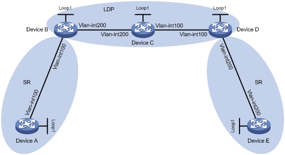
Table 1 Interface and IP address assignment
|
Device |
Interface |
IP address |
Device |
Interface |
IP address |
|
Device A |
Loop1 |
1.1.1.1/32 |
Device B |
Loop1 |
2.2.2.2/32 |
|
|
Vlan-Int100 |
10.0.0.1/24 |
|
Vlan-Int100 |
10.0.0.2/24 |
|
Device C |
Loop1 |
3.3.3.3/32 |
|
Vlan-Int200 |
11.0.0.1/24 |
|
|
Vlan-Int100 |
12.0.0.1/24 |
Device D |
Loop1 |
4.4.4.4/32 |
|
|
Vlan-Int200 |
11.0.0.2/24 |
|
Vlan-Int100 |
12.0.0.2/24 |
|
Device E |
Loop1 |
5.5.5.5/32 |
|
Vlan-Int200 |
13.0.0.1/24 |
|
|
Vlan-Int200 |
13.0.0.2/24 |
|
|
|
Analysis
To enable the two SR networks to communicate across the LDP network, you must perform the following tasks:
· Configure Device A, Device B, Device C, Device D, and Device E to run IS-IS.
· Configure Device B, Device C, and Device D to run LDP.
· Configure Device A, Device B, Device D, and Device E to run MPLS SR.
Software versions used
This configuration example was created and verified on R6301.
Procedures
Configuring Device A
# Configure IP addresses and masks for interfaces. (Details not shown.)
# Configure IS-IS to achieve network level connectivity and set the IS-IS cost style to wide.
<DeviceA> system-view
[DeviceA] isis 1
[DeviceA-isis-1] network-entity 00.0000.0000.0001.00
[DeviceA-isis-1] cost-style wide
[DeviceA-isis-1] quit
[DeviceA] interface vlan-interface 100
[DeviceA-Vlan-interface100] isis enable 1
[DeviceA-Vlan-interface100] quit
[DeviceA] interface loopback 1
[DeviceA-LoopBack1] isis enable 1
[DeviceA-LoopBack1] quit
# Set the LSR ID.
[DeviceA] mpls lsr-id 1.1.1.1
# Enable MPLS SR.
[DeviceA] isis 1
[DeviceA-isis-1] address-family ipv4
[DeviceA-isis-1-ipv4] segment-routing mpls
[DeviceA-isis-1-ipv4] quit
# Configure the SRGB.
[DeviceA-isis-1] segment-routing global-block 16000 16999
[DeviceA-isis-1] quit
# Configure IS-IS prefix SID.
[DeviceA] interface loopback 1
[DeviceA-LoopBack1] isis prefix-sid index 10
[DeviceA-LoopBack1] quit
Configuring Device B
# Configure IP addresses and masks for interfaces. (Details not shown.)
# Configure IS-IS to achieve network level connectivity and set the IS-IS cost style to wide.
<DeviceB> system-view
[DeviceB] isis 1
[DeviceB-isis-1] network-entity 00.0000.0000.0002.00
[DeviceB-isis-1] cost-style wide
[DeviceB-isis-1] quit
[DeviceB] interface vlan-interface 100
[DeviceB-Vlan-interface100] isis enable 1
[DeviceB-Vlan-interface100] quit
[DeviceB] interface vlan-interface 200
[DeviceB-Vlan-interface200] isis enable 1
[DeviceB-Vlan-interface200] quit
[DeviceB] interface loopback 1
[DeviceB-LoopBack1] isis enable 1
[DeviceB-LoopBack1] quit
# Set the LSR ID.
[DeviceB] mpls lsr-id 2.2.2.2
# Configure LDP.
[DeviceB] mpls ldp
[DeviceB-ldp] quit
[DeviceB] interface vlan-interface 200
[DeviceB-Vlan-interface200] mpls enable
[DeviceB-Vlan-interface200] mpls ldp enable
[DeviceB-Vlan-interface200] quit
# Enable MPLS SR.
[DeviceB] isis 1
[DeviceB-isis-1] address-family ipv4
[DeviceB-isis-1-ipv4] segment-routing mpls
[DeviceB-isis-1-ipv4] quit
# Configure the SRGB.
[DeviceB-isis-1] segment-routing global-block 17000 17999
[DeviceB-isis-1] quit
# Configure IS-IS prefix SID.
[DeviceB] interface loopback 1
[DeviceB-LoopBack1] isis prefix-sid index 20
[DeviceB-LoopBack1] quit
Configuring Device C
# Configure IP addresses and masks for interfaces. (Details not shown.)
# Configure IS-IS to achieve network level connectivity and set the IS-IS cost style to wide.
<DeviceC> system-view
[DeviceC] isis 1
[DeviceC-isis-1] network-entity 00.0000.0000.0003.00
[DeviceC-isis-1] cost-style wide
[DeviceC-isis-1] quit
[DeviceC] interface vlan-interface 100
[DeviceC-Vlan-interface100] isis enable 1
[DeviceC-Vlan-interface100] quit
[DeviceC] interface vlan-interface 200
[DeviceC-Vlan-interface200] isis enable 1
[DeviceC-Vlan-interface200] quit
[DeviceC] interface loopback 1
[DeviceC-LoopBack1] isis enable 1
[DeviceC-LoopBack1] quit
# Set the LSR ID.
[DeviceC] mpls lsr-id 3.3.3.3
# Configure LDP.
[DeviceC] mpls ldp
[DeviceC-ldp] quit
[DeviceC] interface vlan-interface 100
[DeviceC-Vlan-interface100] mpls enable
[DeviceC-Vlan-interface100] mpls ldp enable
[DeviceC-Vlan-interface100] quit
[DeviceC] interface vlan-interface 200
[DeviceC-Vlan-interface200] mpls enable
[DeviceC-Vlan-interface200] mpls ldp enable
[DeviceC-Vlan-interface200] quit
Configuring Device D
# Configure IP addresses and masks for interfaces. (Details not shown.)
# Configure IS-IS to achieve network level connectivity and set the IS-IS cost style to wide.
<DeviceD> system-view
[DeviceD] isis 1
[DeviceD-isis-1] network-entity 00.0000.0000.0004.00
[DeviceD-isis-1] cost-style wide
[DeviceD-isis-1] quit
[DeviceD] interface vlan-interface 100
[DeviceD-Vlan-interface100] isis enable 1
[DeviceD-Vlan-interface100] quit
[DeviceD] interface vlan-interface 200
[DeviceD-Vlan-interface200] isis enable 1
[DeviceD-Vlan-interface200] quit
[DeviceD] interface loopback 1
[DeviceD-LoopBack1] isis enable 1
[DeviceD-LoopBack1] quit
# Set the LSR ID.
[DeviceD] mpls lsr-id 4.4.4.4
# Configure LDP.
[DeviceD] mpls ldp
[DeviceD-ldp] quit
[DeviceD] interface vlan-interface 100
[DeviceD-Vlan-interface1001] mpls enable
[DeviceD-Vlan-interface100] mpls ldp enable
[DeviceD-Vlan-interface100] quit
# Enable MPLS SR.
[DeviceD] isis 1
[DeviceD-isis-1] address-family ipv4
[DeviceD-isis-1-ipv4] segment-routing mpls
[DeviceD-isis-1-ipv4] quit
# Configure the SRGB.
[DeviceD-isis-1] segment-routing global-block 18000 18999
[DeviceD-isis-1] quit
# Configure IS-IS prefix SID.
[DeviceD] interface loopback 1
[DeviceD-LoopBack1] isis prefix-sid index 40
[DeviceD-LoopBack1] quit
Configuring Device E
# Configure IP addresses and masks for interfaces. (Details not shown.)
# Configure IS-IS to achieve network level connectivity and set the IS-IS cost style to wide.
<DeviceE> system-view
[DeviceE] isis 1
[DeviceE-isis-1] network-entity 00.0000.0000.0005.00
[DeviceE-isis-1] cost-style wide
[DeviceE-isis-1] quit
[DeviceE] interface vlan-interface 200
[DeviceE-Vlan-interface200] isis enable 1
[DeviceE-Vlan-interface200] quit
[DeviceE] interface loopback 1
[DeviceE-LoopBack1] isis enable 1
[DeviceE-LoopBack1] quit
# Set the LSR ID.
[DeviceE] mpls lsr-id 5.5.5.5
# Enable MPLS SR.
[DeviceE] isis 1
[DeviceE-isis-1] address-family ipv4
[DeviceE-isis-1-ipv4] segment-routing mpls
[DeviceE-isis-1-ipv4] quit
# Configure the SRGB.
[DeviceE-isis-1] segment-routing global-block 19000 19999
[DeviceE-isis-1] quit
# Configure IS-IS prefix SID.
[DeviceE] interface loopback 1
[DeviceE-LoopBack1] isis prefix-sid index 50
[DeviceE-LoopBack1] quit
Verifying the configuration
# Display LDP LSP information on Device B.
[DeviceB] display mpls ldp lsp
Status Flags: * - stale, L - liberal, B - backup, N/A - unavailable
FECs: 5 Ingress: 3 Transit: 3 Egress: 2
FEC In/Out Label Nexthop OutInterface
1.1.1.1/32 24116/-
-/24117(L)
2.2.2.2/32 3/-
-/24120(L)
3.3.3.3/32 -/3 11.0.0.2 Vlan200
24121/3 11.0.0.2 Vlan200
4.4.4.4/32 -/24119 11.0.0.2 Vlan200
24118/24119 11.0.0.2 Vlan200
5.5.5.5/32 -/24118 11.0.0.2 Vlan200
24117/24118 11.0.0.2 Vlan200
# Display IS-IS SRLSP information on Device B.
[DeviceB] display mpls lsp protocol isis
FEC Proto In/Out Label Interface/Out NHLFE
1.1.1.1/32 ISIS 17010/3 Vlan100
1.1.1.1/32 ISIS -/3 Vlan100
2.2.2.2/32 ISIS 17020/- -
4.4.4.4/32 ISIS 17040/24119 Vlan200
4.4.4.4/32 ISIS -/24119 Vlan200
5.5.5.5/32 ISIS 17050/24118 Vlan200
5.5.5.5/32 ISIS -/24118 Vlan200
The output shows that the IS-IS SRLSP entries for Device D and Device E are using LDP labels.
Configuration files
#
isis 1
cost-style wide
segment-routing global-block 16000 16999
network-entity 00.0000.0000.0001.00
#
address-family ipv4 unicast
segment-routing mpls
#
mpls lsr-id 1.1.1.1
#
vlan 1
#
vlan 100
#
interface LoopBack1
ip address 1.1.1.1 255.255.255.255
isis enable 1
isis prefix-sid index 10
#
interface Vlan-interface100
ip address 10.0.0.1 255.255.255.0
isis enable 1
#
interface HundredGigE1/0/1
port link-mode bridge
port access vlan 100
combo enable fiber
#
· Device B:
#
isis 1
cost-style wide
segment-routing global-block 17000 17999
network-entity 00.0000.0000.0002.00
#
address-family ipv4 unicast
segment-routing mpls
#
mpls lsr-id 2.2.2.2
#
vlan 1
#
vlan 100
#
vlan 200
#
mpls ldp
#
interface LoopBack1
ip address 2.2.2.2 255.255.255.255
isis enable 1
isis prefix-sid index 20
#
interface Vlan-interface100
ip address 10.0.0.2 255.255.255.0
isis enable 1
#
interface Vlan-interface200
ip address 11.0.0.1 255.255.255.0
isis enable 1
mpls enable
mpls ldp enable
#
interface HundredGigE1/0/1
port link-mode bridge
port access vlan 100
combo enable fiber
#
interface HundredGigE1/0/2
port link-mode bridge
port access vlan 200
combo enable fiber
#
· Device C:
#
isis 1
cost-style wide
network-entity 00.0000.0000.0003.00
#
mpls lsr-id 3.3.3.3
#
vlan 1
#
vlan 100
#
vlan 200
#
mpls ldp
#
interface LoopBack1
ip address 3.3.3.3 255.255.255.255
isis enable 1
#
interface Vlan-interface100
ip address 12.0.0.1 255.255.255.0
isis enable 1
mpls enable
mpls ldp enable
#
interface Vlan-interface200
ip address 11.0.0.2 255.255.255.0
isis enable 1
mpls enable
mpls ldp enable
#
interface HundredGigE1/0/1
port link-mode bridge
port access vlan 200
combo enable fiber
#
interface HundredGigE1/0/2
port link-mode bridge
port access vlan 100
combo enable fiber
#
· Device D:
#
isis 1
cost-style wide
segment-routing global-block 18000 18999
network-entity 00.0000.0000.0004.00
#
address-family ipv4 unicast
segment-routing mpls
#
mpls lsr-id 4.4.4.4
#
vlan 1
#
vlan 100
#
vlan 200
#
mpls ldp
#
interface LoopBack1
ip address 4.4.4.4 255.255.255.255
isis enable 1
isis prefix-sid index 40
#
interface Vlan-interface100
ip address 12.0.0.2 255.255.255.0
isis enable 1
mpls enable
mpls ldp enable
#
interface Vlan-interface200
ip address 13.0.0.1 255.255.255.0
isis enable 1
#
interface HundredGigE1/0/1
port link-mode bridge
port access vlan 100
combo enable fiber
#
interface HundredGigE1/0/2
port link-mode bridge
port access vlan 200
combo enable fiber
#
· Device E:
#
isis 1
cost-style wide
segment-routing global-block 19000 19999
network-entity 00.0000.0000.0005.00
#
address-family ipv4 unicast
segment-routing mpls
#
mpls lsr-id 5.5.5.5
#
vlan 1
#
vlan 200
#
interface LoopBack1
ip address 5.5.5.5 255.255.255.255
isis enable 1
isis prefix-sid index 50
#
interface Vlan-interface200
ip address 13.0.0.2 255.255.255.0
isis enable 1
#
interface HundredGigE1/0/1
port link-mode bridge
port access vlan 200
combo enable fiber
#
Related documentation
· H3C S6800[S6860][S6861] (R27xx) & S6820 (R630x) Switch Series MPLS Configuration Guide
· H3C S6800[S6860][S6861] (R27xx) & S6820 (R630x) Switch Series MPLS Command Reference